Creating a Voice Enabled Application
“Voice” in this section means “voice quality audio” or any sound with a similar bandwidth. Voice can be compressed into a data stream that can easily be transmitted over a low-bandwidth radio protocol. TI offers a voice solution based on sampling a Pulse Density Modulation (PDM) microphone.
This section aims to describe the firmware that implements the TI voice solution.
Note
In addition to PDM based voice solution, active development is also being done in the following areas:
- External Codec support for line in/analog mic
- Additional compression methods such as mSBC
- LaunchPad based voice receiver
This development is hosted on TI’s SimpleLink Github Page
Currently the ble_examples repo contains sample applications with some of the
above features. Check back often for examples using other wireless technologies,
or improvements to the BLE examples.
PDM Voice
No external codec is required as the bit stream from a digital microphone can be read directly by the device, and the PDM stream can be processed in software.
The figure below shows the components required to use the TI voice solution
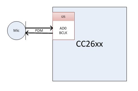
Figure 100. PDM Voice Block Diagram
Sampling
The voice solution uses the following sampling parameters:
- Sample rate: 16kHz
- Bit Depth: 16 bits
Voice quality audio is a type of audio where all information can be obtained with a low sampling rate. Whereas the typical audible spectrum is up to 20kHz, 8kHz is more than enough for voice. 16kHz sampling rate captures all information contained up to 8kHz.
The voice quality of TI’s solution has been qualified by Nuance and is sufficient for voice recognition solutions.
PDM Driver
The PDM driver is responsible for sampling the microphone data and formatting it for the user application to use.
- Collects PDM data from a PDM data microphone sampled at 1.021MHz
- Decimates the PDM input to a PCM data stream with a 16kHz sample rate and 16 bit resolution
- Encodes the PCM data using a software codec based on IMA ADPCM.
More information on the PDM driver can be found at PDM Driver Doxygen
I2S Peripheral for PDM
The PDM driver uses the I2S hardware module within the CC2640R2F to sample the PDM microphone. I2S was selected because it is a high performance peripheral capable of generating the waveforms required for PDM sampling.
More information on the I2S peripheral can be found in the CC26xx Technical Reference Manual.
The (PDM specific) I2S driver layer is implemented within the PDM Util layer. See the PDM Util Doxygen for more information.
A three wire interface is used to interface to the PDM mic. See PDM Voice Block Diagram for more info.
- GPIO: Mic power
- BCLK: Audio clock signal
- ADx: PDM input stream from mic
The settings for the I2S peripheral are initialzed in PDMCC26XX_I2S_open(). The default I2S settings will work out of the box for PDM sampling. Advanced applications of the driver may require changes that are out of the scope of this document.
The GPIO pin that powers the mic is set within by the PDMCC26XX_HWAttrs, this is generally set within the board file.
IMA ADPCM Compression
If applyCompression is enabled in the PDMCC26XX_Params
then the PDM driver will use the IMA ADPCM codec implementation bundled with the
driver.
This sample implementation can be found within the TI IMA ADPCM Codec Doxygen files. Note that the TI codec includes implementation for the decode algorithms, which can be used on voice receiver devices.
PDM Driver Metadata
When using the ADPCM codec the driver will append metadata to each frame before sending it to the application. This metadata is used to ensure data integrity.
ADPCM is a differential compression format. This means that each sample depends on the previous. The metadata provides the information contained in the last sample of the previous frame. So, if a frame is lost then it will not affect the next frame. See PDMCC26XX_metaData for more information.
| Type | Description |
|---|---|
| uint8_t | Sequence Number |
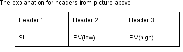
| int8_t | Step Index (SI) |
| int16_t | Predicted Value (PV) |
Driver Output
The driver outputs configurable length frames.
Frame length can be modified to fit the chosen RF protocol. The driver defaults to 192 samples per frame.
At default settings, the PDM driver produces frames that are 12ms long.
(192 S) / (16 kS/s) = 12ms
Throughput Requirement
Now that we know what the driver output we can calculate the required throughput. By this we mean how many bits per second is produced by the driver. Let us use the typical configuration with 192 samples per frame. Recall that 192 samples per frame means a frame duration of 12ms.
| Data | Calculation | rate |
|---|---|---|
| Raw | (16000 S / s) * (16 bits / S) | 256kbps |
| Compressed | 256kbps / 4 | 64kbps |
| Metadata | 4 B / 12ms | 2.67kbps |
| Compressed frame with metadata | 64kbps + 2.667kbps | 66.67kpbs |
Voice over BLE
There is no standard way of transmitting voice over BLE so a custom profile must be used. TI’s custom profile utilizes the GATT layer of the BLE-Stack to transmit voice frames. This is known as a Voice over GATT Profile approach (VoGP).
TI Voice Profile (VoGP)
The audio data is transmitted using a proprietary service with UUID
F000B000-0451-4000-B000-000000000000. This service is composed of the
following 2 characteristics:
Note
The characteristics below use the 128-bit TI base UUID of the
format F000XXXX-0451-4000-B000-000000000000 where XXXX is their
shortened 16bit UUID. For brevity, this document will refer to the
characteristics by their 16-bit short UUID.
| Name | UUID | Description | GATT Properties |
| AUDIOPROFILE_START | 0xB001 | The start characteristic is used to transmit a start command before the streaming starts and a stop command as the last packet of a stream. | GATT_PROP_READ, GATT_PROP_NOTIFY |
| AUDIOPROFILE_AUDIO | 0xB002 | AUDIOPROFILE_AUDIO is used as the audio stream characteristic, all audio frames will be transmitted using this characteristic. | GATT_PROP_READ, GATT_PROP_NOTIFY |
GATT_Notification() was selected as the primary vehicle for transmitting voice data over BLE in the voice profile implementation.
Notifications were selected because they have low packet overhead and
are asynchronous in nature. These qualities make
notifications ideal for voice streaming applications.
Before the voice stream begins, the peer device must enable notifications by
writing 01:00 to the CCCD of both AUDIOPROFILE_START and AUDIOPROFILE_AUDIO.
If notifications are not enabled, the remote will not stream voice data.
The basic flow of a voice transmission is:
- CC2640R2F sends a start command (0x04) notification (if enabled) on the AUDIOPROFILE_START characteristic.
- CC2640R2F starts streaming voice data. See Sequence diagram for Voice Transmission for more details
- CC2650 sends a stop command (0x00) notification on the AUDIOPROFILE_START characteristic.
See the figure below for an illustration of voice transmission over BLE. See BLE Voice Frame Data for more information about the contents of the BLE voice frame.
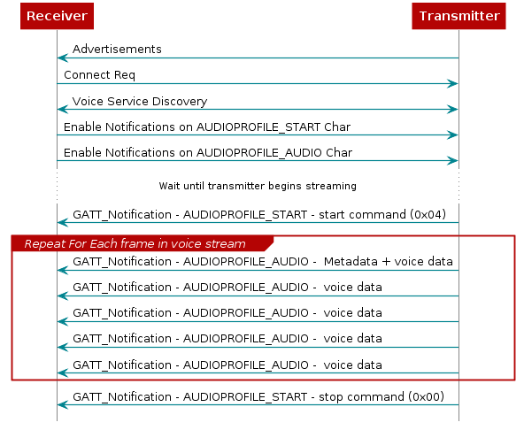
Figure 101. Sequence diagram for Voice Transmission
BLE Voice Frame Data
By default the voice profile will send 20 bytes of application data per notification. Thus, it is thus ideal to choose a PDM driver frame length that is a multiple of 20 bytes.
Recall from PDM Driver Metadata that each frame should contain 4 bytes metadata as well. There is a compromise between frame duration and overhead, which was found to be optimized at a total frame length of 100 bytes, which includes 4 bytes metadata.
The numbered headers in the voice frame above are the metadata fields provided by the PDM driver. See PDM Driver Metadata for an explanation of the metadata fields.
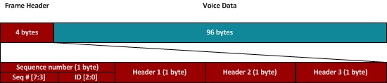
Figure 102. One audio packet.
When transmitted over the air, the audio frames are fragmented into 20 byte notifications, this means that each audio frame is sent as 5 notifications:
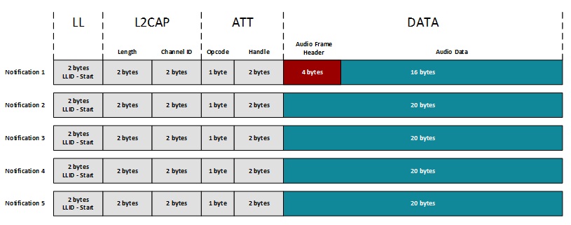
Figure 103. One audio frame sent over the air as 5 notification.
Modifiying the Latency
The built in flow control in the Bluetooth low energy Protocol is used to ensure delivery of full audio frames during streaming.
Since the header of each audio frame contains the information required to decode that frame separately, the safest way to discard data in e.g. a noisy environment is to discard the full frame.
The PDM driver will drop full audio frames when there are no available buffers, and the application will handle one frame at a time until it has been successfully queued up in the TX FIFO within the BLE-Stack.
As mentioned above, the application must service a PDM buffer every 2ms.
If the application requires a longer contiguous chunk of processing time or a
marginal RF environment is causing many re-try events then the number of PDM
buffers can be tweaked by modifying MINIMUM_PDM_BUFFER_QUEUE_DEPTH.
Each increase in MINIMUM_PDM_BUFFER_QUEUE_DEPTH triggers a corresponding
increase of 2ms of latency which allows the application more time to process.
The cost of the increased latency is increased RAM useage.
The user application should be profiled to find the optimal tradeoff between the expected RF conditions, RAM useage, and latency.
Throughput Requirement for BLE
The general required throughput for sending audio frame has been covered in Throughput Requirement. Here we will cover the calculation for required throughput when we take BLE specific headers into consinderation.
| Data | Calculation | rate |
|---|---|---|
| L2CAP and ATT header | (7 * 5) B / 12ms | 23.33kbps |
| Complete packets overhead | (21 * 5) B / 12ms | 70kpbs |
From Throughput Requirement, we learned that the required thoughput
for audio frame is 66.67kbps. After adding the overhead from BLE headers,
the required throughput is 70 + 66.67 = 136.67kbps
The hid_adv_remote application will try to transmit as many available audio notifications as possible for every connection event. This means that the required throughput can be obtained with different settings for the connection interval as longs as enough packets can be transmitted in each connection event to successfully reach the ~417 notifications per second limit.
1 notification = 20 B audio data = 160 bits audio data.
Required audio data throughput = 66670bps.
66670 / 160 ~= 417 notifications per second
Typically a connection interval of 10ms can be used where 3-5 notifications are transmitted every connection event.