The CC2640R2F SDK Platform
Architecture
The TI royalty-free Bluetooth low energy software development kit (SDK) is a complete software platform for developing single-mode Bluetooth low energy applications. This kit is based on the SimpleLink CC2640R2F, complete System-on-Chip (SoC) Bluetooth low energy solution. The CC2640R2F combines a 2.4-GHz RF transceiver, 128-KB in-system programmable memory, 20KB of SRAM, and a full range of peripherals. The device is centered on an ARM® Cortex®-M3 series processor that handles the application layer and Bluetooth low energy protocol stack and an autonomous radio core centered on an ARM Cortex®-M0 processor that handles all the low-level radio control and processing associated with the physical layer and parts of the link layer. The sensor controller block provides additional flexibility by allowing autonomous data acquisition and control independent of the Cortex-M3 processor, further extending the low-power capabilities of the CC2640R2F. Figure 3. shows the block diagram. For more information on the CC2640R2F, see the CC26xx Technical Reference Manual.
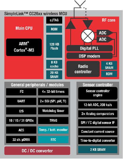
Figure 3. SimpleLink CC2640R2F Block Diagram
Hardware and Software Architecture
This section aims to introduce the different cores within the CC2640R2F, how they interact, and the firmware that runs on them. The information presented here should be considered as an overview. For detailed descriptions of the hardware described here, refer to the chapter 23 of the CC26xx Technical Reference Manual.
ARM Cortex M0 (Radio Core)
The Cortex M0 (CM0) core within the CC2640R2F is responsible for both interfacing to the radio hardware, and translating complex instructions from the Cortex M3 (CM3) core into bits that are sent over the air using the radio. For the Bluetooth low energy protocol, the CM0 implements the PHY layer of the protocol stack. Often, the CM0 is able to operate autonomously, which frees up the CM3 for higher-level protocol and application-layer processing.
The CM3 communicates with the CM0 through a hardware interface called the RF doorbell, which is documented in section 23.2 of the CC26xx Technical Reference Manual. The radio core firmware is not intended to be used or modified by the application developer.
ARM Cortex M3 (System Core)
The system core (CM3) is designed to run the Bluetooth low energy protocol stack from the link layer up to the user application. The link layer interfaces to the radio core through a software module called the RF driver, which sits above the RF doorbell. The RF driver runs on the CM3 and acts as an interface to the radio on the CC2640R2F, and also manages the power domains of the radio hardware and core. Documentation for the RF driver can be found at the TI-RTOS Drivers Reference. Above the RF driver is the TI Bluetooth low energy protocol stack, which is implemented in library code.
The application developer interfaces with the protocol stack through a set of APIs (ICall) to implement a Bluetooth low energy application. The rest of this document intends to document application development on the CC2640R2F using the Bluetooth low energy stack.
BLE-Stack Protocol Stack and Application Configurations
Figure 4. shows the platform that supports two different protocol stack and application configurations.
- Single device: The controller, host, profiles, and application are all implemented on the CC2640R2F as a true single-chip solution. This configuration is the simplest and most common when using the CC2640R2F. This configuration is used by most of TI’s sample projects. This configuration is the most cost-effective technique and provides the lowest-power performance.
- Simple network processor: The Simple Network Processor (SNP) implements the controller and host layers of the BLE-Stack. Additionally, the SNP exposes an interface for scheduling communication between the stack and an external MCU. This accelerates dual MCU designs because the application processor (AP) is only responsible for managing custom profiles and application code. Stack-related functionality, such as security, is implemented on the SNP. The SNP currently supports the peripheral and broadcaster GAP roles. Communication with the SNP is carried out through the SNP API. The SNP API is built on the Unified Network Processor Interface (UNPI), which supports UART and SPI transport layers. For more information, reference the Unified Network Processor Interface wiki page. TI also provides the SAP library, which implements a UNPI master and the SNP API. The SAP library can be ported to any TI-RTOS-capable processor, or used as a reference for developing a custom dual MCU solution. For a description of the SNP, see the README.html page within the simple_np folder, advanced users can read the SNP API Reference for a summary of the supported commands.
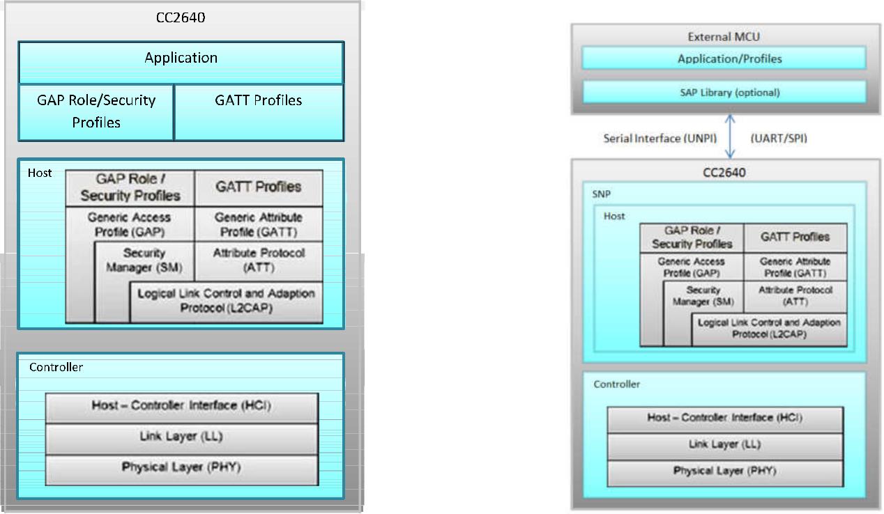
Figure 4. Single-Device Processor and Simple Network Processor Configurations
Solution Platform
This section describes the various components that are installed with the BLE-Stack 3.00.01 and the directory structure of the protocol stack and any tools required for development. Figure 5. shows the BLE-Stack 3.00.01 development system.
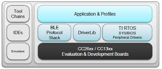
Figure 5. Bluetooth low energy Stack Development System
The solution platform includes the following components:
- TI’s Real-Time Operating System (TI-RTOS) with the TI-RTOS kernel, optimized power management support, and peripheral drivers (SPI, UART, and so forth)
- CC26xxware DriverLib provides a register abstraction layer and is used by software and drivers to control the CC2640R2F SoC.
- The Bluetooth low energy protocol stack is provided in library form with parts of the protocol stack in the CC2640R2F ROM.
- Sample applications and profiles make starting development using both proprietary and generic solutions easier.
The following integrated development environments (IDEs) are supported:
- IAR Embedded Workbench for ARM
- Code Composer Studio™ (CCS)
Refer to the SDK release notes for the specific IDE versions supported by this release.
BLE Software Architecture
The CC2640R2F Bluetooth low energy software environment consists of the following parts:
- An application image with the TI-RTOS kernel, drivers and Bluetooth profile
- A stack image or library that implements Bluetooth low energy protocol
TI-RTOS is a real-time, pre-emptive, multithreaded operating system that runs the software solution with task synchronization. Both the application and Bluetooth low energy protocol stack exist as separate tasks within the RTOS. The Bluetooth low energy protocol stack has the highest priority. A messaging framework called indirect call (ICall) is used for thread-safe synchronization between the application and stack. Figure 6. shows the architecture.
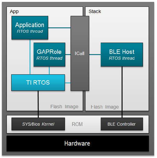
Figure 6. Example Software Architecture
- The stack image includes the lower layers of the Bluetooth low energy protocol stack from the LL up to and including the GAP and GATT layers. Most of the Bluetooth low energy protocol stack code is provided as a library.
- The application image includes the RTOS, profiles, application code, drivers, and the ICall module.
Protocol Stack Build Configurations
The BLE-Stack applications have different options for configuring the protocol stack to maximize system implementations. These options are described below along with the relevant advantages and limitations.
Note
This section aims to explain the two supported protocol stack build configurations. Additionally, the protocol stack itself may be configured to conditionally pull in different library builds based on the features needed. Configuring the protocol stack is covered in Stack Configurations
Stack Library Configuration (_stack_library)
In BLE-Stack 3.00.01, stack can be built as a library that can be statically linked to
the application. Projects with build with this new configuration can be
identified by project build configurations with _stack_library in its
configuration name. Using this build configuration will yield additional flash
footprint optimizations by the linker since the application and stack can share
contiguous flash pages. The gained footprint savings will however prevent
split-image application- or on-chip OAD downloads. See
Available CCS project build configurations and
Available IAR project build configurations for the available project build
configurations. Stack library projects have the following properties
- Stack project generates a static library (.lib)
- Application project will now link the stack in as a library
- There is no explicit app/stack boundary. The application’s link step decides the memory locations of the code within the stack_library. There are some exceptions to this such as SNV.
- This architecture saves flash by allowing the linker work more efficiently.
- These projects used the improved ICall architecture
Split Image Configuration
As with previous BLE-Stack 2.x SDK releases, application and stack images are built as two separate projects that generate two separate images. These images occupy separate, non-overlapping flash memory pages. The split image configuration is useful in purposes such as on-chip OAD where it could be advantageous to perform independent application or stack downloads. Split image projects have the following properties:
- Fixed stack entry point
- Stack project generates a separate executable (.hex, .out, .bin)
- Explicit Flash/RAM boundaries between app and stack
- Independent update of stack/app (API compatibility must be ensured by the user)
Project Build Configurations
Sample applications within the BLE-Stack 3.00.01 portion of the SimpleLink CC2640R2 SDK support multiple build configurations to enable using the protocol stack build types discussed above. Other build configurations may have been created to support features such as RCOSC or OAD out of the box. The table below gives a summary of the build configurations found within BLE-Stack 3.00.01 and their compatibility with one another.
| Project type | Project’s build configuration | Description |
| Application | FlashROM | Application image build configuration. Requires companion Stack FlashROM (split image configuration) |
| FlashROM_StackLibrary | Application build configuration linked to Stack library (fully executable) | |
| FlashROM_StackLibrary_RCOSC | Application build configuration linked to Stack library for 32-kHz crystal-less device configuration | |
| FlashROM_OAD_ImgB | OAD on-chip customer application FlashROM image | |
| FlashROM_OAD_Offchip | OAD off-chip application FlashROM configuration | |
| Stack | FlashROM_Library | Stack library build configuration |
| FlashROM | Stack image using protocol stack in ROM configuration |
Note
Some of the build configurations above may be located in a separate
project for CCS, for example simple_peripheral_cc2640r2lp_app_oad_offchip.
However the principles of the table above can still be applied. Always
consult the README.html file of the specific sample application for
more information on it’s supported build configurations. Additionally,
refer to Available CCS project build configurations
Converting Library Build to Split Image
All BLE-Stack 3.00.01 projects will support improved ICall and the Library build configuration. However, not all projects will have ICall in non-Library Build configuration. In other words, not all projects will have a split application/stack build configuration.
A split Application and Stack configuration is required for on-chip OAD applications where only the stack or the application image is planned to be upgraded. Library configuration only supports full application + stack image off-chip OAD.
This section outlines how to convert an ICall Library Project to a split application and stack project.
Application Side (IAR)
Select the Application Project as Active Project
Delete
StackLibraryIDE Folder or exclude library file from build.Open Project Properties
Various ways to do this:
- Right Click on Project > Options
- From Toolbar : Project > Options
Go to C/C++ Compiler Options, Preprocessor tab
Select C/C++ Compiler from the Category List
Select Preprocessor Tab
Remove
STACK_LIBRARYSymbolUnder
Defined SymbolsremoveSTACK_LIBRARYGo to Linker Options, Config Tab
Select Linker from the Category List
Select Config tab in the Window
Apply the following changes:
- Linker configuration file:
1
$SRC_EX$/common/cc26xx/iar/cc26xx_app.icf
Instead of
1
$SRC_EX$/common/cc26xx/iar/cc26xx_app_and_stack.icf
- Configuration file symbol definitions:
1
CC2650=2
Remove
1
FLASH_ROM_BUILD=2
Go to Linker Options, Library Tab
Select Linker from the Category List
Select Library tab in the Window
Modify Additional Linker Library Paths
Change Additional Libraries text field to use:
1
$ROM$\ble_rom_releases\cc26xx_r2\Final_Release\common_r2.symbols
Instead of:
1
$ROM$\ble_rom_releases\cc26xx_r2\Final_Release\ble_r2.symbols
Lastly, remove:
1
$TI_RTOS_DRIVERS_BASE$\ti\drivers\rf\lib\rf_singleMode_cc26x0r2.aem3
Pre-Modifications:
1
2
3
4
5
6
$ROM$\ble_rom_releases\cc26xx_r2\Final_Release\ble_r2.symbols
$CC26XXWARE$\driverlib\bin\iar\driverlib.lib
$TI_RTOS_KERNEL$\packages\ti\dpl\lib\dpl_cc26x0r2.aem3
$TI_RTOS_DRIVERS_BASE$\ti\drivers\lib\drivers_cc26x0r2.aem3
$TI_RTOS_DRIVERS_BASE$\ti\drivers\rf\lib\rf_singleMode_cc26x0r2.aem3
$TI_RTOS_DRIVERS_BASE$\ti\display\lib\display.aem3
Post-Modifications:
1
2
3
4
5
$ROM$\ble_rom_releases\cc26xx_r2\Final_Release\common_r2.symbols
$CC26XXWARE$\driverlib\bin\iar\driverlib.lib
$TI_RTOS_KERNEL$\packages\ti\dpl\lib\dpl_cc26x0r2.aem3
$TI_RTOS_DRIVERS_BASE$\ti\drivers\lib\drivers_cc26x0r2.aem3
$TI_RTOS_DRIVERS_BASE$\ti\display\lib\display.aem3
Go to Linker Options, Extra Options
Select Linker from the Category List
Select Extra Options tab in the Window
Remove
lib_linker.cmdThe window should have the following content after removal
1
2
3
--keep __vector_table
-f $PROJ_DIR$\..\config\configPkg\linker.cmd
-f $PROJ_DIR$\..\config\iar_boundary.xcl
Stack Side (IAR)
Select the Stack Project as Active Project
Open Project Properties
Various ways to do this:
- Right Click on Project > Options
- From Toolbar : Project > Options
Go to General Options, Output Tab
Select General Options from the Category List
Select the Output tab
Select
Executablefor Output FileSelect the
ExecutableRadio Button under Output File.Note
This will reset Debugger Settings!
Go to C/C++ Compiler Options, Preprocessor tab
Select C/C++ Compiler from the Category List
Select Preprocessor Tab
Remove
STACK_LIBRARYSymbolUnder
Defined SymbolsremoveSTACK_LIBRARYGo to Build Options
Select Build Options from Category List
Add Boundary Tool to Post Build
This tool hands information to the Application regarding Stack Entry Point.
Add the following to Post_Build command line:
1
"$TOOLS_BLE$/frontier/frontier.exe" iar "$PROJ_DIR$/$CONFIG_NAME$/List/simple_peripheral_cc2640r2lp_stack.map" "$PROJ_DIR$/../config/iar_boundary.bdef" "$PROJ_DIR$/../config/iar_boundary.xcl"Go to Linker Options, Config Tab
Select Linker from the Category List
Select Config tab in the Window
Add
lib_linker.cmdThis tool resolves undefined rom function references.
Select
Use command line optionsEnter the following into the Command Line Options Textfield
1
-f $PROJ_DIR$/../config/lib_linker.cmd
Reconfigure Debugger Settings
Use XDS110 for the CC2640R2 Launchpad. Use the application project as reference.
At this point, you will have a functional ICall Non-Library build of the project.
Standard Project Task Hierarchy
Considering the simple_peripheral project as an example, these tasks are listed by priority. A higher task number corresponds to a higher priority task:
- Priority 5: Bluetooth low energy protocol stack task (must be highest priority)
- Priority 3: GapRole task (peripheral role)
- Priority 1: Application task (simple_peripheral)
TI-RTOS Overview introduces TI-RTOS tasks. Overview describes interfacing with the Bluetooth low energy protocol stack. GAPRole Task describes the GapRole task. Pre-main initialization describes the application task.
Directory Structure
The default install location is: C:\ti\simplelink_cc2640r2_sdk_x_xx_xx_xx.
The SDK installs to this location by default. For the purposes of this document, consider the above path to the BLE-Stack root directory; it will be omitted. All paths will be relative to the BLE-Stack root directory. Opening up the root install directory shows the new parent folders within the SDK, as shown in Table 3.
| BLE-Stack 3.00.01 folders | Purpose |
|---|---|
| docs\ | The docs directory now contains all relevant documents included with the CC2640R2F SDK. Refer to the Documentation Overview master page. |
| examples\ | The CC2640R2F SDK includes ble examples as well as TI-RTOS kernel and TI-RTOS driver examples. |
| kernel\ | The TI-RTOS kernel is now included with the CC2640R2F SDK. |
| source\ | The source\ directory include source for BLE-Stack, TI-RTOS kernel and drivers, and various middleware modules. |
| tools\ | Tools such as BTool |
Examples Folder
The examples\ folder contains example source files for the BLE-Stack, TI-RTOS kernel, and TI-RTOS drivers. All the source code supporting the SimpleLink CC2640R2 SDK examples can be found at *examples\rtos\CC2640R2_LAUNCHXL\. Examples for each product can be found within their respective folders and are accessible via various means as shown in Examples available for the CC2640R2F platform.
| Type of examples | Example subdirectory | How to open the examples |
|---|---|---|
| BLE-Stack | blestack\ | Imported via TI Resource Explorer
Opened as existing IAR projects
|
| TI-RTOS Kernel | sysbios\ | |
| TI-RTOS Drivers | drivers\ |
For TI-RTOS Kernel and TI-RTOS driver examples, see the linked documentation. To help select a specific BLE example, see BLE examples available for the CC2640R2F platform. As with previous BLE-Stack releases, each example contains a toolchain subdirectory for CCS and IAR.
IAR examples are available as .eww projects whereas CCS project are imported.
See Table 1. for a list of examples supported by the SDK.
Source Folder
The source\ti\ folder contains libraries and source files for the BLE-Stack, TI-RTOS drivers, and various shared modules. They can be found within their respective folders as shown in CC2640R2F SDK’s source\ti\ directory.
| source\ti\ | subdirectory | Purpose |
|---|---|---|
| blestack\ | Root source directory for the BLE-Stack | |
| blelib\ | Prebuilt BLE-Stack libraries | |
| boards\ | Sample board files for use with BLE-Stack | |
| common\ | Linker, RTOS config, and middleware used by the stack | |
| config\ | Symbol files for various stack builds and configurations | |
| controller\ | Header files for the BLE controller layer | |
| hal\ | Hardware abstraction layer files for Stack | |
| heapmgr\ | BLE-Stack Heap Manager | |
| host\ | Header files for the BLE host layers | |
| icall\ | Source files for the ICall module | |
| inc\ | Header files used to interface with the BLE-Stack | |
| microstack\ | Source files for the Micro BLE Stack | |
| npi\ | Source files for the both NPI modules | |
| osal\ | Source support files used by the BLE-Stack | |
| profiles\ | Sample BLE profile implementations | |
| rom\ | BLE-Stack ROM symbol file | |
| services\ | Miscellaneous support files | |
| symbols\ | ROM patch support files | |
| target\ | Board gateway folder | |
| devices\ | Support files from driverlib | |
| display\ | Display module | |
| drivers\ | TI-RTOS drivers source and libraries | |
| grlib\ | Graphics library (not used by BLE-Stack examples) | |
| mw\ | Other middleware modules dependent on TI-RTOS drivers | |
Working With Hex and Binary Files
BLE-Stack projects have project build configurations in which the application and stack projects produce an Intel®-extended hex file in their respective output folders. These hex files lack overlapping memory regions and can be programmed individually with a flash programming tool, such as SmartRF Flash Programmer 2. . To simplify the flash programming process, you can combine the application and stack hex files into a super hex file manually or using freely available tools. Information on the Intel Hex standard.
One example for creating the super hex file is with the IntelHex python script hex_merge.py, available at IntelHex launchpad. To merge the hex files, install Python® 2.7.x and add it to your system path environment variables.
Warning
Note that when using any python script, you must use a compatible version of Python. Refer to the tool documentation or contact the developer to verify compatibility.
The following is an example usage to create a merged simple_peripheral_cc2640r2lp.hex file consisting of the individual application and stack hex files:
1 2 3 4 5 6 | C:\Python27\Scripts>python hexmerge.py \
-o .\simple_peripheral_cc2640r2lp_merged.hex \
-r 0000:1FFFF
simple_peripheral_cc2640r2lp_app.hex:0000:1FFFF
simple_peripheral_cc2640r2lp_stack.hex
--overlap=error
|
If conversion of the super hex to binary is desired, this can be accomplished with the “hex2bin.py” or similar tools that support the hex standard.
1 2 3 | C:\Python27\Scripts>python hex2bin.py \
simple_peripheral_cc2640r2lp_merged.hex \
simple_peripheral_cc2640r2lp_merged.bin
|
Programming Internal Flash with the ROM Bootloader
The CC2640R2F internal flash memory can be programmed using the bootloader in the ROM of the device. Both UART and SPI protocols are supported. For more details on the programming protocol and requirements, see the Bootloader chapter of the CC26xx Technical Reference Manual.
Note
Because the ROM bootloader uses predefined DIO pins for internal flash programming, allocate these pins in the layout of your board. For details on the pins allocated to the bootloader based on the chip package type, see CC26xx Technical Reference Manual.
Installing BLE-Stack 3.00.01
The BLE-Stack 3.00.01 is a wireless component included as part of the SimpleLink CC2640R2 SDK. All path and file references in this document assume that the SimpleLink CC2640R2 SDK is installed to the default path (<SDK_INSTALL_DIR>).
TI recommends making a backup copy of the SimpleLink CC2640R2 SDK before to making any changes. The BLE-Stack 3.00.01 uses paths relative to the SimpleLink CC2640R2 SDK and therefore is portable in respect to any valid installation path for the SimpleLink CC2640R2 SDK.
Attention
Code Composer Studio creates a dynamic installation variable for a discovered SimpleLink CC2640R2 SDK instances. For more information, see Discovering CCS products.
Note
If installing the SimpleLink CC2640R2 SDK to a non-default path, do not exceed the maximum length of the file system namepath. Actual paths may differ from the figures.
SimpleLink CC2640R2 SDK also installs XDCTools if not already present. See the release notes for required version numbers. Newer versions of tools may not be compatible with this SDK release. Check the TI Bluetooth LE Wiki for the latest supported tool versions.
Developing with CCS
Installing Code Composer Studio (CCS)
The CCS toolchain contains many features beyond the scope of this document. More information and documentation can be found on the CCS Webpage.
Check the BLE-Stack 3.00.01 release notes to see which CCS version to use and any required workarounds. Object code produced by CCS may differ in size and performance as compared to IAR produced object code.
The following procedure describes installing and configuring the correct version of CCS and the necessary tools.
Install Code Composer Studio for ARM
- Download Code Composer Studio
- Start the installation process and accept the license agreement. It is recommended to install CCS in its default location.
- In the Processor Support section, select SimpleLink CC13xx and CC26xx Wireless MCUs.
- Under the Debug Probes section, CCS will install support for TI XDS Debug Probe Support. This option supports the XDS110 debugger.
- Start the installation by selecting Finish.
Attention
The version required is stated in the release notes.
Verify ARM Compiler Tools version
- If needed, the CCS and ARM compiler versions can be verified by going to into Help -> About Code Composer Studio. Under the Installation Details button, you can determine the ARM Compiler Tools version. Please ensure this version satisfies the version requirements as stated in the release notes.
- If an update is required, refer to Installing a Specific TI ARM Compiler for the procedure to install the required TI ARM Compiler version.
Installing a Specific TI ARM Compiler
To install a specific TI ARM Compiler, refer to the following steps and Figure 7.
- Help -> Install New Software
- Under the Work with: drop-down list, select Code Generation Tools Update
- Uncheck Show only the latest versions of available software
- Expand TI Compiler Update.
- Select the desired ARM Compiler Tools version as stated in the release notes.
- Press Next to complete the installation. You may have to restart CCS afterwards.
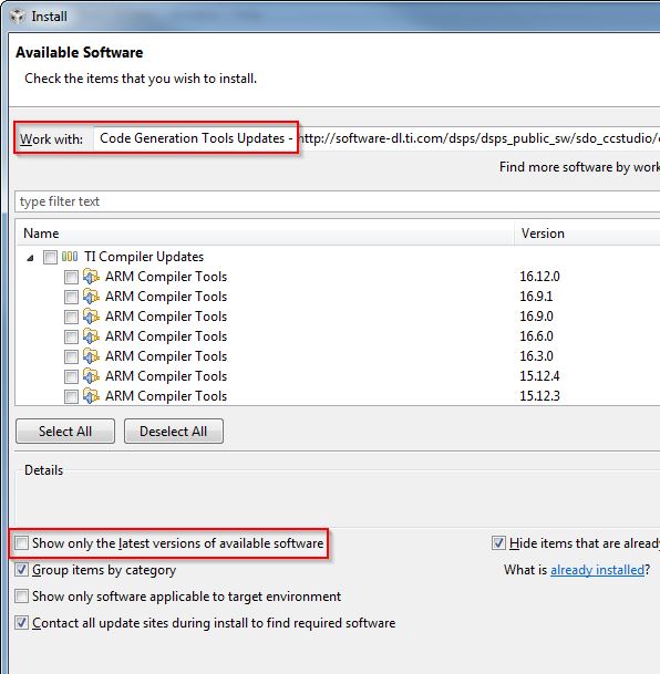
Figure 7. TI ARM Compiler Version in Code Composer Studio
Importing CCS projects
This section describes how to import and build an existing project and references the simple_peripheral project. All of the BLE-Stack 3.00.01 projects included in the development kit have a similar structure.
Note
Before importing a BLE-Stack 3.00.01 project, CCS must discover the SimpleLink CC2640R2 SDK. Install the SimpleLink CC2640R2 SDK before opening or after restarting CCS.
Open the CCS IDE from the Start Menu.
Create a workspace.
Attention
Ensure that the CCS workspace path does not contain a whitespace.
Import a CCS Project
Select Project -> Import CCS Projects...
Select search directory: <SDK_INSTALL_DIR>\examples\rtos\CC2640R2_LAUNCHXL\blestack\simple_peripheral\tirtos\ccs
CCS discovers several projects, each having a unique build configuration.
- For this example, select simple_peripheral_cc2640r2lp_app and simple_peripheral_cc2640r2lp_stack_library
Select Finish
Caution
Similar as with all other TI projects, CCS needs to discover the SimpleLink CC2640R2 SDK before BLE-Stack 3.00.01 projects can be imported.
Click Finish to import (see Figure 8.).
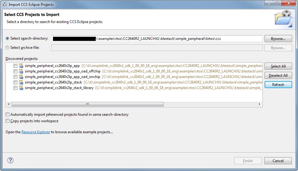
Figure 8. Import CCS Projects
Discovering CCS products
Code Composer Studio automatically discovers the SimpleLink CC2640R2 SDK if it installed in its
default installation directory (c:/ti). Once discovered by CCS, it defines a
build environment variable named COM_TI_SIMPLELINK_CC2640R2_SDK_INSTALL_DIR
which is used by BLE-Stack 3.00.01 projects.
If a BLE-Stack 3.00.01 project is imported from a path other than what was specified
during the SimpleLink CC2640R2 SDK installation, the COM_TI_SIMPLELINK_CC2640R2_SDK_INSTALL_DIR
variable must be redefined after the import proceeding at a project-by-project
basis.
To redefine this variable:
Open the CCS project’s properties (Project -> Properties)
Navigate to Resource -> Linked Resources and edit
COM_TI_SIMPLELINK_CC2640R2_SDK_INSTALL_DIRand have it point to your imported root directory location.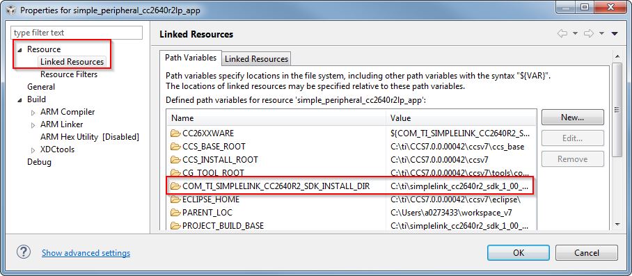
Figure 9. Redefining
COM_TI_SIMPLELINK_CC2640R2_SDK_INSTALL_DIR
BLE-Stack 3.00.01 CCS project build configurations
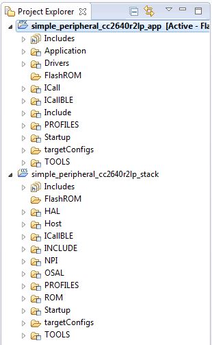
Figure 10. CCS Project Explorer
This and all BLE-Stack 3.00.01 project workspaces contain various projects and build configurations as shown in Table 6. *_StackLibrary build configurations build the stack as a library as described in Stack Library Configuration (_stack_library).
Click the project name in the file explorer to select the project as the active project. In Figure 10., the application is selected as the active project. Each of these projects produces a separate, downloadable image.
The simple_peripheral sample project is the primary sample application for the description of a generic application in this guide. The simple_peripheral project implements a basic Bluetooth low energy peripheral device including a GATT server with GATT services. This project can be used as a framework for developing peripheral-role applications.
| Project type | Project naming convention | Project’s build configuration | Compatible project complement |
|---|---|---|---|
| Application | *_cc2640r2lp_app |
FlashROM | *_cc2640r2lp_stack |
| FlashROM_StackLibrary | *_cc2640r2lp_stack_library |
||
| FlashROM_StackLibrary_RCOSC | *_cc2640r2lp_stack_library |
||
*_cc2640r2lp_app_oad_onchip |
FlashROM_OAD_ImgB | *_cc2640r2lp_stack with FlashROM configuration |
|
*_cc2640r2lp_app_oad_offchip |
FlashROM_OAD_Offchip | *_cc2640r2lp_stack with FlashROM configuration |
|
| Stack | *_cc2640r2lp_stack_library |
FlashROM_Library | *_cc2640r2lp_app with FlashROM_StackLibrary configuration |
*_cc2640r2lp_stack |
FlashROM | *_cc2640r2lp_app with FlashROM configuration |
Compiling and Download
For all build configurations, the stack project should always be built before the application project.
For projects where the stack is built as a library:
Build the stack library project.
- Set the stack project as the active project.
- Select Project -> Build All to build the stack project.
Build the application project.
- Set the application project as the active project.
- Select Project -> Build All to build the application project.
Load the whole application
- Select Run -> Debug to download the application
Note
Application project that consume the stack in a library form will not have hard defined image boundaries.
After the initial build, if the stack project is not modified, only the application project needs to be rebuilt.
For projects where the stack and application are split images (not a library):
Build the stack project.
- Set the stack project as the active project.
- Select Project -> Build All to build the stack project.
Build the application project.
- Set the application project as the active project.
- Select Project -> Build All to build the application project.
Load the stack project
- Set the stack project as the active project.
- Select Run -> Debug to download the stack
Load the application project
- Set the application project as the active project.
- Select Run -> Debug to download the application
Note
The stack project defines the flash and RAM boundary parameters used by the application project. Any modifications to the stack project require a rebuild of the stack project, followed by a rebuild of the application project to use the new boundary settings. See Frontier Tool Operation.
After the initial build, if the stack project is not modified, only the application project needs to be rebuilt.
Caution
Do not modify the CPU Variant in the project settings. All sample projects are configured with a CPU type, and changing this setting (that is, from CC2640R2F) may result in build errors.
Sample applications that implement the Over the Air Download (OAD) firmware update capability require the Boot Image Manager (BIM) project to be built. Refer to the Over the Air Download (OAD) section for more details.
Accessing Preprocessor Symbols
Various C preprocessor symbols may need to be set or adjusted at the project level. The following procedure describes how to access and modify preprocessor symbols.
- Open Project Properties
- Navigate to Build -> ARM Compiler -> Predefined Symbols
- Use the buttons highlighted in Figure 11. to add, delete, or edit a preprocessor.
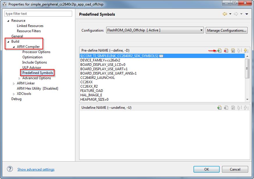
Figure 11. CCS Predefined Symbols
Accessing Linker Symbols
Linker symbols may need to be set or adjusted at the project level in order to control the memory layout of the generated image. The following procedure describes how to access and modify linker symbols.
- Open Project Properties
- Navigate to Build -> ARM Linker -> Command File Preprocessing
- Use the buttons highlighted in Figure 12. to add, delete, or edit a linker symbol.
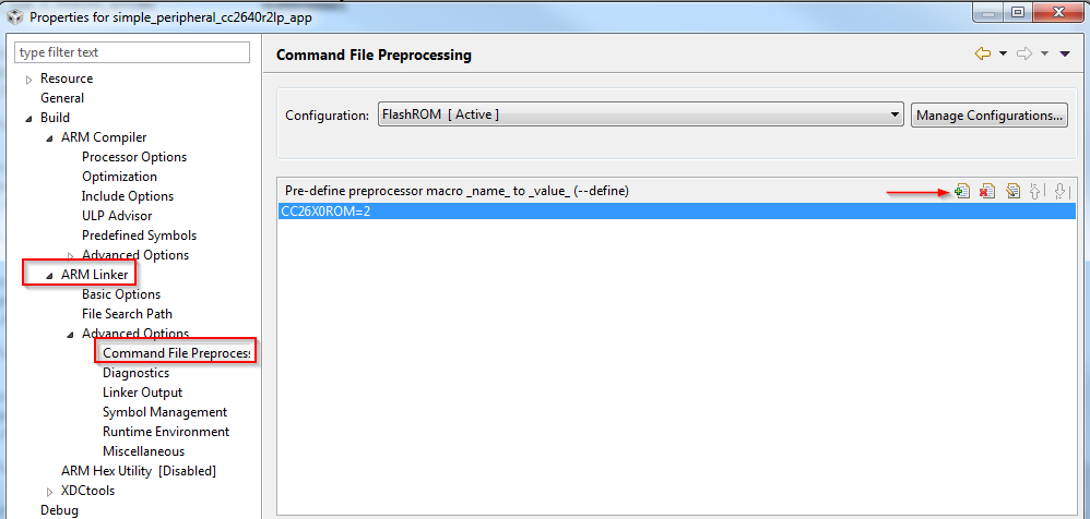
Figure 12. CCS Linker Symbols
Additional training and support for CCS
For additional training and support with Code Composer Studio, refer to: Code Composer Studio Wiki Code Composer Studio Training
Developing with IAR
Installing IAR
The IAR toolchain contains many features beyond the scope of this document. More information and documentation can be found at IAR.com.
Check the BLE-Stack 3.00.01 release notes to see which IAR version to use and any required workarounds. Object code produced by IAR may differ in size and performance as compared to CCS produced object code.
The following procedure describes installing and configuring the correct version of IAR and the necessary tools.
Install IAR Embedded Workbench for ARM
Download and install IAR EW ARM
To get IAR, choose one of the following methods:
- Download the IAR Embedded Workbench 30-Day Evaluation Edition – This version of IAR is free, has full functionality, and includes all of the standard features. The size-limited Kickstart evaluation option is not compatible with this SDK.
- Purchase the full-featured version of IAR Embedded Workbench – For complete BLE application development using the CC2640R2F, TI recommends purchasing the complete version of IAR without any restrictions. You can find the information on purchasing the complete version of IAR.
Attention
The version required is stated in the release notes. Opening IAR project files with a previous version of IAR may cause project file corruption.
Show Build Messages
TI recommends showing all the build output messages for full verbosity during building. To do this, go to Tools -> Options and set Show Build Messages to All (see Figure 14.)
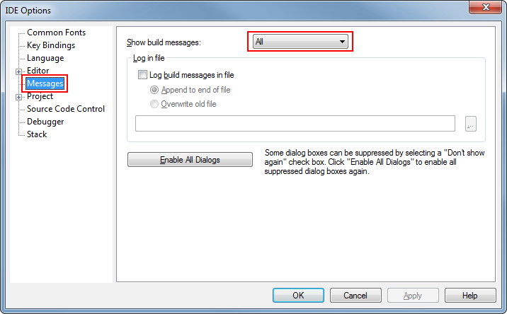
Figure 14. Show All Build Messages in IAR
Opening IAR Projects
Note
TI-RTOS driver and kernel examples are imported for IAR rather than supplied as pre-configured IAR workspace files. Instructions on how to create these projects are found here: Creating TI-RTOS (driver/kernel) Applications in IAR Embedded Workbench
This section describes how to open and build an existing project and references the simple_peripheral project. All of the BLE-Stack 3.00.01 projects included in the development kit have a similar structure.
Open the IAR Embedded Workbench IDE from the Start Menu.
Open an IAR workspace project: File -> Open -> Workspace...
- For this example, select <SDK_INSTALL_DIR>\examples\rtos\CC2640R2_LAUNCHXL\blestack\simple_peripheral\tirtos\iar\simple_peripheral.eww
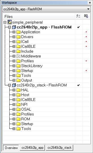
Figure 15. IAR Workspace Pane
This workspace file is for the simple_peripheral project. When selected, the files associated with the workspace become visible in the Workspace pane on the left side of the screen. See Figure 15.
Select either project as the active project by clicking the respective tab at the bottom of the workspace pane. In Figure 15., the Overview tab is selected. This tab displays the file structure for both projects simultaneously. In this case, use the drop-down menu at the top of the workspace pane to select the active project. Each of these projects produces a separate downloadable object. The simple_peripheral sample project is the primary reference target for the description of a generic application in this guide. The simple_peripheral project implements a basic BLE-Stack peripheral device including a GATT server with GATT services. This project can be a framework for developing peripheral-role applications.
BLE-Stack 3.00.01 IAR project build configurations
This and all BLE-Stack 3.00.01 project workspaces contain various projects and build configurations as shown in Table 7. *_StackLibrary build configurations build the stack as a library as described in Stack Library Configuration (_stack_library).
| Project type | Project’s build configuration | Compatible project complement |
|---|---|---|
| Application | FlashROM | Stack - FlashROM |
| FlashROM_StackLibrary | Stack - FlashROM_StackLibrary | |
| FlashROM_StackLibrary_RCOSC | Stack - FlashROM_StackLibrary | |
| FlashROM_OAD_ImgB | Stack - FlashROM | |
| FlashROM_OAD_Offchip | Stack - FlashROM | |
| Stack | FlashROM_Library | Application - FlashROM_Library |
| FlashROM | Application - FlashROM |
Compile and Download
For all build configurations, the stack project should always be built before the application project.
For projects where the stack is built as a library:
Build the stack library project.
- Select the stack project.
- Select Project -> Make to build the stack.
Build the application project.
- Select the application project.
- Select Project -> Make to build the application.
Load the whole application
- To download and debug: Select Project -> Download and Debug
- To download without debugging: Select Project -> Download -> Download Active Application
Note
Application project that consume the stack in a library form will not have hard defined image boundaries.
After the initial build, if the stack project is not modified, only the application project needs to be rebuilt.
For projects where the stack and application are split images (not a library):
Build the stack project.
- Select the stack project.
- Select Project -> Make to build the stack.
Build the application project.
- Select the application project.
- Select Project -> Make to build the application.
Load the stack project.
- Select Project -> Download -> Download Active Application to download the stack project.
Load the application project.
- To download and debug: Select Project -> Download and Debug
- To download without debugging: Select Project -> Download -> Download Active Application
Note
The stack project defines the flash and RAM boundary parameters used by the application project. Any modifications to the stack project require a rebuild of the stack project, followed by a rebuild of the application project to use the new boundary settings. See Frontier Tool Operation.
After the initial build, if the stack project is not modified, only the application project needs to be rebuilt.
When the application is downloaded (that is, flash memory programmed), you can debug without reflashing the device. Go to Project -> Debug without Downloading.
Caution
Do not modify the CPU Variant in the project settings. All sample projects are configured with a CPU type, and changing this setting (that is, from CC2640R2F) may result in build errors.
Sample applications that implement the Over the Air Download (OAD) firmware update capability require the Boot Image Manager (BIM) project to be built. Refer to the Over the Air Download (OAD) section for more details.
Accessing Preprocessor Symbols
Various C preprocessor symbols may need to be set or adjusted at the project level. The following procedure describes how to access and modify preprocessor symbols.
- Open the Project’s Options and select the C/C++ Compiler Category.
- Open the Preprocessor tab.
- View the Defined symbols box (see Figure 16.).
- Add or edit the preprocessor symbols.
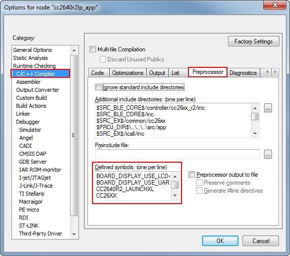
Figure 16. IAR Defined Symbols Box
Accessing Linker Symbols
Linker symbols may need to be set or adjusted at the project level in order to control the memory layout of the generated image. The following procedure describes how to access and modify linker symbols.
- Open the Project’s Options and select the Linker Category.
- Open the Config tab.
- View the Configuration File symbol definitions box (see Figure 17.).
- Add or edit the preprocessor symbols.
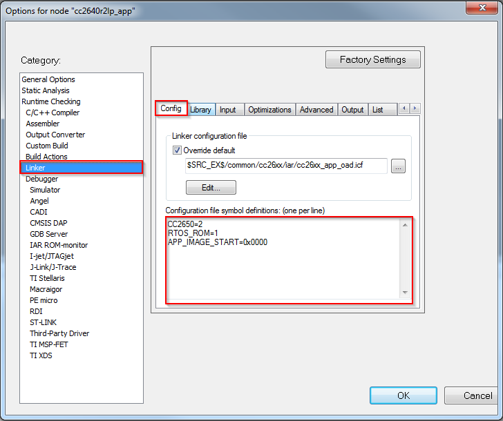
Figure 17. IAR Defined Symbols Box
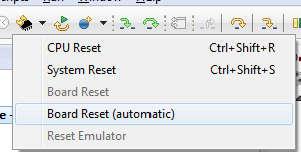
Resetting the CC2640R2F in IAR
Select the Board Reset option from the following Reset (back arrow) Debug Menu drop-down box.
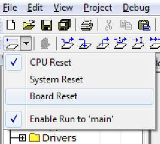
Figure 18. IAR Board Reset
TI-RTOS Overview
TI-RTOS is the operating environment for Bluetooth low energy projects on CC2640R2F devices. The TI-RTOS kernel is a tailored version of the legacy SYS/BIOS kernel and operates as a real-time, preemptive, multi-threaded operating system with drivers, tools for synchronization and scheduling.
Threading Modules
The TI-RTOS kernel manages four distinct context levels of thread execution as shown in Figure 19. The list of thread modules are shown below in a descending order in terms of priority.
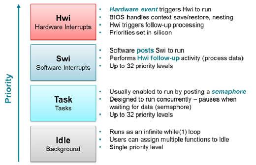
Figure 19. TI-RTOS Execution Threads
This section describes these four execution threads and various structures used throughout the TI-RTOS for messaging and synchronization. In most cases, the underlying TI-RTOS functions have been abstracted to higher-level functions in util.c (Util). The lower-level TI-RTOS functions are described in the TI-RTOS Kernel API Guide found here TI-RTOS Kernel User Guide. This document also defines the packages and modules included with the TI-RTOS.
Hardware Interrupts (Hwi)
Hwi threads (also called Interrupt Service Routines or ISRs) are the threads with the highest priority in a TI-RTOS application. Hwi threads are used to perform time critical tasks that are subject to hard deadlines. They are triggered in response to external asynchronous events (interrupts) that occur in the real-time environment. Hwi threads always run to completion but can be preempted temporarily by Hwi threads triggered by other interrupts, if enabled. Specific information on the nesting, vectoring, and functionality of interrupts can be found in the CC26xx Technical Reference Manual.
Generally, interrupt service routines are kept short as not to affect the hard real-time system requirements. Also, as Hwis must run to completion, no blocking APIs may be called from within this context.
TI-RTOS drivers that require interrupts will initialize the required interrupts for the assigned peripheral. See Drivers for more information.
Note
Debugging provides an example of using GPIOs and Hwis. While the SDK includes a peripheral driver library to abstract hardware register access, it is suggested to use the thread-safe TI-RTOS drivers as described in Drivers.
The Hwi module for the CC2640R2F also supports Zero-latency interrupts. These interrupts do not go through the TI-RTOS Hwi dispatcher and therefore are more responsive than standard interrupts, however this feature prohibits its interrupt service routine from invoking any TI-RTOS kernel APIs directly. It is up to the ISR to preserve its own context to prevent it from interfering with the kernel’s scheduler.
For the Bluetooth low energy protocol stack to meet RF time-critical requirements, all application-defined Hwis execute at the lowest priority. TI does not recommend modifying the default Hwi priority when adding new Hwis to the system. No application-defined critical sections should exist to prevent breaking TI-RTOS or time-critical sections of the Bluetooth low energy protocol stack. Code executing in a critical section prevents processing of real-time interrupt-related events.
Software Interrupts (Swi)
Patterned after hardware interrupts (Hwi), software interrupt threads provide additional priority levels between Hwi threads and Task threads. Unlike Hwis, which are triggered by hardware interrupts, Swis are triggered programmatically by calling certain Swi module APIs. Swis handle threads subject to time constraints that preclude them from being run as tasks, but whose deadlines are not as severe as those of hardware ISRs. Like Hwis, Swi threads always run to completion. Swis allow Hwis to defer less critical processing to a lower-priority thread, minimizing the time the CPU spends inside an interrupt service routine, where other Hwis can be disabled. Swis require only enough space to save the context for each Swi interrupt priority level, while Tasks use a separate stack for each thread.
Similar with Hwis, Swis should be kept to short and may not include any blocking
API calls. This allows high priority tasks such as the wireless protocol
stack to execute as needed. It is suggested to _post() some TI-RTOS
synchronization primitive to allow for further post processing from within a
Task context. See Figure 20. to illustrate such a
use-case.
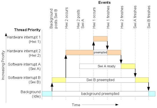
Figure 20. Preemption Scenario
The commonly used Clock module operates from within a Swi context. It is important that functions called by a Clock object do not invoke blocking APIs and are rather short in execution.
Task
Task threads have higher priority than the background (Idle) thread and lower priority than software interrupts. Tasks differ from software interrupts in that they can wait (block) during execution until necessary resources are available. Tasks require a separate stack for each thread. TI-RTOS provides a number of mechanisms that can be used for inter-task communication and synchronization. These include Semaphores, Event, Message queues, and Mailboxes.
See Tasks for more details.
Idle Task
Idle threads execute at the lowest priority in a TI-RTOS application and are executed one after another in a continuous loop (the Idle Loop). After main returns, a TI-RTOS application calls the startup routine for each TI-RTOS module and then falls into the Idle Loop. Each thread must wait for all others to finish executing before it is called again. The Idle Loop runs continuously except when it is preempted by higher-priority threads. Only functions that do not have hard deadlines should be executed in the Idle Loop.
For CC2640R2F devices, the idle task allows the Power Policy Manager to enter the lowest allowable power savings.
Kernel Configuration
A TI-RTOS application configures the TI-RTOS kernel using a configuration
(.cfg file) that is found within the project. In IAR and CCS
projects, this file is found in the application project workspace under the
TOOLS folder.
The configuration is accomplished by selectively including or using
RTSC modules available to the kernel. To use a module, the .cfg
calls xdc.useModule() after which it can set various options as defined
in the TI-RTOS Kernel User Guide.
Note
Projects in the BLE-Stack (such as simple_peripheral) typically will
contain an app_ble.cfg configuration file.
Some of the option that can be configured in the .cfg file include but are
not limited to:
- Boot options
- Number of Hwi, Swi, and Task priorities
- Exception and Error handling
- The duration of a System tick (the most fundamental unit of time in the TI-RTOS kernel).
- Defining the application’s entry point and interrupt vector
- TI-RTOS heaps and stacks (not to be confused with other heap managers!)
- Including pre-compiled kernel and TI-RTOS driver libraries
- System provides (for
System_printf())
Whenever a change in the .cfg file is made, you will rerun the XDCTools’
configuro tool. This step is already handled for you as a pre-build step in
the provided IAR and CCS examples.
Note
The name of the .cfg doesn’t really matter. A project should however only
include one .cfg file.
For CC26xx and CC13xx devices, a TI-RTOS kernel exists in ROM.
Typically for flash footprint savings, the .cfg will include the kernel’s
ROM module as shown in Listing 1.
/* ================ ROM configuration ================ */
/*
 * To use BIOS in flash, comment out the code block below.
 */
if (typeof NO_ROM == 'undefined' || (typeof NO_ROM != 'undefined' && NO_ROM == 0))
{
  var ROM = xdc.useModule('ti.sysbios.rom.ROM');
  if (Program.cpu.deviceName.match(/CC26/)) {
      ROM.romName = ROM.CC2640R2F;
  }
  else if (Program.cpu.deviceName.match(/CC13/)) {
      ROM.romName = ROM.CC1350;
  }
}
The TI-RTOS kernel in ROM is optimized for performance. If additional instrumentation is required in your application (typically for debugging), you must include the TI-RTOS kernel in flash which will increase flash memory consumption. Shown below is a short list of requirements to use the TI-RTOS kernel in ROM.
BIOS.assertsEnabledmust be set tofalseBIOS.logsEnabledmust be set tofalseBIOS.taskEnabledmust be set totrueBIOS.swiEnabledmust be set totrueBIOS.runtimeCreatesEnabledmust be set totrue- BIOS must use the
ti.sysbios.gates.GateMutexmoduleClock.tickSourcemust be set toClock.TickSource_TIMERSemaphore.supportsPrioritymust befalse- Swi, Task, and Hwi hooks are not permitted
- Swi, Task, and Hwi name instances are not permitted
- Task stack checking is disabled
Hwi.disablePrioritymust be set to0x20Hwi.dispatcherAutoNestingSupportmust be set to true- The default Heap instance must set to the
ti.sysbios.heaps.HeapMemmanager
For additional documentation in regards to the list described above, see the TI-RTOS Kernel User Guide.
Creating vs. Constructing
Most TI-RTOS modules commonly have _create() and _construct() APIs to
initialize primitive instances. The main runtime differences between the two
APIs are memory allocation and error handling.
Create APIs perform a memory allocation from the default TI-RTOS heap before initialization. As a result, the application must check the return value for a valid handle before continuing.
1 2 3 4 5 6 7 8 9 10 | Semaphore_Handle sem;
Semaphore_Params semParams;
Semaphore_Params_init(&semParams);
sem = Semaphore_create(0, &semParams, NULL); /* Memory allocated in here */
if (sem == NULL) /* Check if the handle is valid */
{
System_abort("Semaphore could not be created");
}
|
Construct APIs are given a data structure with which to store the instance’s variables. As the memory has been pre-allocated for the instance, error checking may not be required after constructing.
1 2 3 4 5 6 7 8 9 | Semaphore_Handle sem;
Semaphore_Params semParams;
Semaphore_Struct structSem; /* Memory allocated at build time */
Semaphore_Params_init(&semParams);
Semaphore_construct(&structSem, 0, &semParams);
/* It's optional to store the handle */
sem = Semaphore_handle(&structSem);
|
Thread Synchronization
The TI-RTOS kernel provides several modules for synchronizing tasks such as Semaphore, Event, and Queue. The following sections discuss these common TI-RTOS primitives.
Semaphores
Semaphores are commonly used for task synchronization and mutual exclusions
throughout TI-RTOS applications. Figure 21. shows the semaphore
functionality. Semaphores can be counting semaphores or binary semaphores.
Counting semaphores keep track of the number of times the semaphore is posted
with Semaphore_post(). When a group of resources are shared between tasks,
this function is useful. Such tasks might call Semaphore_pend() to see if a
resource is available before using one. Binary semaphores can have only two
states: available (count = 1) and unavailable (count = 0). Binary semaphores
can be used to share a single resource between tasks or for a basic-signaling
mechanism where the semaphore can be posted multiple times. Binary semaphores do
not keep track of the count; they track only whether the semaphore has been
posted.
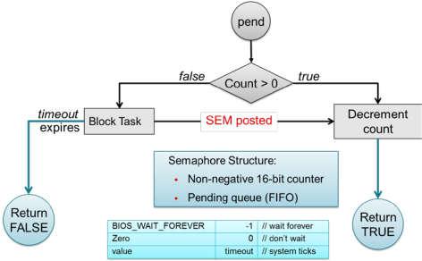
Figure 21. Semaphore Functionality
Initializing a Semaphore
The following code depicts how a semaphore is initialized in TI-RTOS. Semaphores can be created and constructed as explained in Creating vs. Constructing.
See Listing 2. on how to create a Semaphore.
See Listing 3. on how to construct a Semaphore.
Pending on a Semaphore
Semaphore_pend() is a blocking function call. This call may only be called
from within a Task context. A task calling this function will allow lower
priority tasks to execute, if they are ready to run. A task calling
Semaphore_pend() will block if its counter is 0, otherwise it will decrement
the counter by one. The task will remain blocked until another thread calls
Semaphore_post() or if the supplied system tick timeout has occurred;
whichever comes first. By reading the return value of Semaphore_pend() it is
possible to distinguish if a semaphore was posted or if it timed out.
1 2 3 4 5 6 7 8 9 10 11 12 13 14 | bool isSuccessful;
uint32_t timeout = 1000 * (1000/Clock_tickPeriod);
/* Pend (approximately) up to 1 second */
isSuccessful = Semaphore_pend(sem, timeoutInTicks);
if (isSuccessful)
{
System_printf("Semaphore was posted");
}
else
{
System_printf("Semaphore timed out");
}
|
Note
The default TI-RTOS system tick period is 1 millisecond. This default is
reconfigured to 10 microseconds for CC26xx and CC13xx devices by setting
Clock.tickPeriod = 10 in the .cfg file.
Given a system tick of 10 microseconds, timeout in
Listing 4. will be approximately 1 second.
Posting a Semaphore
Posting a semaphore is accomplished via a call to Semaphore_post(). A task
that is pending on a posted semaphore will transition from a blocked state to
a ready state. If no higher priority thread is ready to run, it will allow
the previously pending task to execute. If no task is pending on the semaphore,
a call to Semaphore_post() will increment its counter. Binary semaphores
have a maximum count of 1.
1 | Semaphore_post(sem);
|
Event
Semaphores themselves provide rudimentary synchronization between threads. There are cases just the Semaphore itself is enough to understand on what process needs to be triggered. Often however, a specific causes for the synchronization need to be passed across threads as well. To help accomplish this, one can utilize the TI-RTOS Event module. Events are similar to Semaphores in a sense that each instance of an event object actually contains a Semaphore. The added advantage of using Events lie in the fact that tasks can be notified of specific events in a thread-safe manner.
Initializing an Event
Creating and constructing events follow the same guidelines as explained in Creating vs. Constructing. Shown in Listing 6. is an example on how to construct an Event instance.
1 2 3 4 5 6 7 8 9 | Event_Handle event;
Event_Params eventParams;
Event_Struct structEvent; /* Memory allocated at build time */
Event_Params_init(&eventParams);
Event_construct(&structEvent, 0, &eventParams);
/* It's optional to store the handle */
event = Event_handle(&structEvent);
|
Pending on an Event
Similar to Semaphore_pend(), a task thread would typically block on an
Event_pend() until an event is posted via an Event_post() or if the
specified timeout expired. Shown in Listing 7. is a snippet
of a task pending on any of the 3 sample event IDs shown below.
BIOS_WAIT_FOREVER is used to prevent a timeout from occurring. As a result,
Event_pend() will have one or more events posted in the returned bit-masked
value.
Each event returned from Event_pend() has been automatically cleared within
the event instance in a thread-safe manner. Therefore, it is only necessary to
keep a local copy of posted events. For full details on how to use
Event_pend(), see the TI-RTOS Kernel User Guide.
1 2 3 4 5 6 7 8 9 10 11 12 13 14 15 16 17 18 19 20 21 22 23 24 25 26 27 28 29 30 31 32 33 34 35 | #define START_ADVERTISING_EVT Event_Id_00
#define START_CONN_UPDATE_EVT Event_Id_01
#define CONN_PARAM_TIMEOUT_EVT Event_Id_02
void TaskFxn(..)
{
/* Local copy of events that have been posted */
uint32_t events;
while(1)
{
/* Wait for an event to be posted */
events = Event_pend(event,
Event_Id_NONE,
START_ADVERTISING_EVT |
START_CONN_UPDATE_EVT |
CONN_PARAM_TIMEOUT_EVT,
BIOS_WAIT_FOREVER);
if (events & START_ADVERTISING_EVT)
{
/* Process this event */
}
if (events & START_CONN_UPDATE_EVT)
{
/* Process this event */
}
if (events & CONN_PARAM_TIMEOUT_EVT)
{
/* Process this event */
}
}
}
|
Note
The default TI-RTOS system tick period is 1 millisecond. This default is
reconfigured to 10 microseconds for CC26xx and CC13xx devices by setting
Clock.tickPeriod = 10 in the .cfg file.
Given a system tick of 10 microseconds, timeout in
Listing 4. will be approximately 1 second.
Posting an Event
Events may be posted from any TI-RTOS kernel contexts and is simply done by
calling Event_post() of the event instance and the event ID.
Listing 8. shows how a high priority thread such as a Swi
could post a specific event.
1 2 3 4 5 6 7 8 | #define START_ADVERTISING_EVT Event_Id_00
#define START_CONN_UPDATE_EVT Event_Id_01
#define CONN_PARAM_TIMEOUT_EVT Event_Id_02
void SwiFxn(UArg arg)
{
Event_post(event, START_ADVERTISING_EVT);
}
|
Queues
Queues let applications process messages in a first in, first out (FIFO) order. A project may use a queue to manage internal events coming from application profiles or another task. Clocks must be used when an event must be processed in a time-critical manner. Queues are more useful for message passing across various thread contexts.
The Queue module provides a unidirectional method of message passing between threads using a FIFO. In Figure 22. a queue is configured for unidirectional communication from task A to task B. Task A pushes messages into the queue and task B pops messages from the queue in order. Figure 22. shows the queue messaging process.
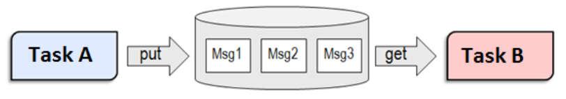
Figure 22. Queue Messaging Process
The TI-RTOS Queue functions have been abstracted into functions in the util.c
file. See the Queue module in the TI-RTOS Kernel User Guide for the
underlying functions. These utility functions combine the Queue module with the
ability to notify the recipient task of an available message through TI-RTOS Event
Module.
In CC2640R2F software, the event used for this process is the same event that the
given task uses for task synchronization through ICall. For an example of this,
see the SimpleBLECentral_enqueueMsg() function. Queues are commonly used to
limit the processing time of application callbacks in the context of the higher
priority threads. In this manner, the higher priority thread queues a message to
the application to process later instead of immediate processing in its own
context.
The Util module contains a set of abstracted TI-RTOS Queue functions as
shown here:
- Util_constructQueue() creates a queue.
- Util_enqueueMsg() puts items into the queue.
- Util_dequeueMsg() gets items from the queue.
Functional Example
Figure 23. and Figure 24. illustrate how a queue can be used to enqueue a button press from Hwi (to Swi in the Board Key module) to be processed within a Task when no other high priority events are occurring. The example was taken from the from the simple_central project in BLE-Stack 3.00.01.
![@startuml
hide footbox
box "Swi context"
participant "Board Key module" as A
participant simple_central.c as B
database appMsgQueue as C
end box
-[#red]> A : Key press interrupt
<[#red]-- A
activate A
autonumber
A -> B : SimpleBLECentral_keyChangeHandler();
activate B
note right: Add SBC_KEY_CHANGE_EVT into the queue
B -> B : SimpleBLECentral_enqueueMsg();
activate B
autonumber stop
B -> : ICall_malloc();
B -> C: Util_enqueueMsg();
activate C
C --> B:
deactivate C
B -> : Event_post();
deactivate B
B --> A
deactivate B
deactivate A
@enduml](../_images/plantuml-0c947cf0f66a5ea55c69bfe1e2f3068eabcbe756.png)
Figure 23. Sequence diagram for enqueuing a message
With interrupts enabled, a pin interrupt can occur asynchronously within a
Hwi context. To keep interrupts as short as possible, the work
associated with the interrupt is deferred to lower priority contexts for
processing. In the simple_central example found in BLE-Stack 3.00.01, pin
interrupts are abstracted via a Board Key module. This module will notify
registered functions via a callback from within a Swi context. In this
case, SimpleBLECentral_keyChangeHandler is the registered callback function.
Step 1 in Figure 23. shows the callback to
SimpleBLECentral_keyChangeHandler when a key is pressed. This event is
placed into the application’s queue for processing.
1 2 3 4 | void SimpleBLECentral_keyChangeHandler(uint8 keys)
{
SimpleBLECentral_enqueueMsg(SBC_KEY_CHANGE_EVT, keys, NULL);
}
|
Step 2 in Figure 23. shows how this key press is enqueued
for simple_central. Here, memory is allocated from ICall_malloc() to be
added to the queue. Once added to the queue, Util_enqueueMsg() will
generate a UTIL_QUEUE_EVENT_ID for the application to process.
1 2 3 4 5 6 7 8 9 10 11 12 13 14 15 16 17 | static uint8_t SimpleBLECentral_enqueueMsg(uint8_t event, uint8_t state, uint8_t *pData)
{
sbcEvt_t *pMsg = ICall_malloc(sizeof(sbcEvt_t));
// Create dynamic pointer to message.
if (pMsg)
{
pMsg->hdr.event = event;
pMsg->hdr.state = state;
pMsg->pData = pData;
// Enqueue the message.
return Util_enqueueMsg(appMsgQueue, sem, (uint8_t *)pMsg);
}
return FALSE;
}
|
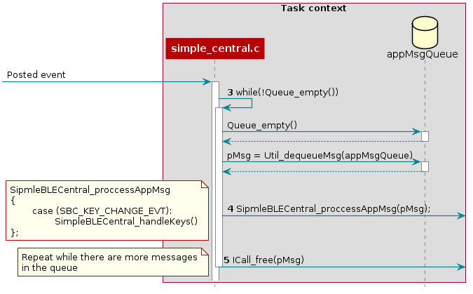
Figure 24. Sequence diagram for dequeuing a message
Step 3 in Figure 24., the simple_central application is
unblocked by the posted UTIL_QUEUE_EVENT_ID event where it proceeds to
check if any messages have been placed in the queue for processing.
1 2 3 4 5 6 7 8 9 10 11 12 13 | // If TI-RTOS queue is not empty, process app message
while (!Queue_empty(appMsgQueue))
{
sbcEvt_t *pMsg = (sbcEvt_t *)Util_dequeueMsg(appMsgQueue);
if (pMsg)
{
// Process message
SimpleBLECentral_processAppMsg(pMsg);
// Free the space from the message
ICall_free(pMsg);
}
}
|
Step 4 in Figure 24., the simple_central application takes the dequeue message and starts processing it.
1 2 3 4 5 6 7 8 9 10 | static void SimpleBLECentral_processAppMsg(sbcEvt_t *pMsg)
{
switch (pMsg->hdr.event)
{
case SBC_KEY_CHANGE_EVT:
SimpleBLECentral_handleKeys(0, pMsg->hdr.state);
break;
//...
}
}
|
Step 5 in Figure 24., the simple_central application can now free the memory.
Note
The Bluetooth low energy stack abstracts the Queue modules via the Util module.
Tasks
TI-RTOS Tasks are equivalent to independent threads that conceptually execute functions in parallel within a single C program. In reality, switching the processor from one task to another helps achieve concurrency. Each task is always in one of the following modes of execution:
- Running: task is currently running
- Ready: task is scheduled for execution
- Blocked: task is suspended from execution
- Terminated: task is terminated from execution
- Inactive: task is on inactive list
One (and only one) task is always running, even if it is only the idle task (see Figure 19.). The current running task can be blocked from execution by calling certain task module functions, as well as functions provided by other modules like Semaphores. The current task can also terminate itself. In either case, the processor is switched to the highest priority task that is ready to run. See the Task module in the package ti.sysbios.knl section of the TI-RTOS Kernel User Guide for more information on these functions.
Numeric priorities are assigned to tasks, and multiple tasks can have the same priority. Tasks are readied to execute by highest to lowest priority level; tasks of the same priority are scheduled in order of arrival. The priority of the currently running task is never lower than the priority of any ready task. The running task is preempted and rescheduled to execute when there is a ready task of higher priority.
In the simple_peripheral application, the Bluetooth low energy protocol stack task is given the highest priority (5) and the application task is given the lowest priority (1).
Initializing a Task
When a task is initialized, it has its own runtime stack for storing local variables as well as further nesting of function calls. All tasks executing within a single program share a common set of global variables, accessed according to the standard rules of scope for C functions. This set of memory is the context of the task. The following is an example of the application task being constructed.
1 2 3 4 5 6 7 8 9 10 11 12 13 14 15 16 17 18 19 20 21 22 23 24 25 26 27 28 29 30 31 32 33 34 35 36 37 38 39 40 41 42 43 44 | #include <xdc/std.h>
#include <ti/sysbios/BIOS.h>
#include <ti/sysbios/knl/Task.h>
/* Task's stack */
uint8_t sbcTaskStack[TASK_STACK_SIZE];
/* Task object (to be constructed) */
Task_Struct task0;
/* Task function */
void taskFunction(UArg arg0, UArg arg1)
{
/* Local variables. Variables here go onto task stack!! */
/* Run one-time code when task starts */
while (1) /* Run loop forever (unless terminated) */
{
/*
* Block on a signal or for a duration. Examples:
* ``Sempahore_pend()``
* ``Event_pend()``
* ``Task_sleep()``
*
* "Process data"
*/
}
}
int main() {
Task_Params taskParams;
// Configure task
Task_Params_init(&taskParams);
taskParams.stack = sbcTaskStack;
taskParams.stackSize = TASK_STACK_SIZE;
taskParams.priority = TASK_PRIORITY;
Task_construct(&task0, taskFunction, &taskParams, NULL);
BIOS_start();
}
|
The task creation is done in the main() function, before the TI-RTOS Kernel’s
scheduler is started by BIOS_start(). The task executes at its assigned
priority level after the scheduler is started.
TI recommends using an existing application task for application-specific
processing. When adding an additional task to the application project, the
priority of the task must be assigned a priority within the TI-RTOS
priority-level range, defined in the TI-RTOS configuration file (.cfg).
Tip
Reduce the number of Task priority levels to gain additional RAM savings in
the TI-RTOS configuration file (.cfg):
Task.numPriorities = 6;
Do not add a task with a priority equal to or higher than the Bluetooth low energy protocol stack task and related supporting tasks (for example, the GapRole task). See Standard Project Task Hierarchy for details on the system task hierarchy.
Ensure the task has a minimum task stack size of 512 bytes of predefined memory. At a minimum, each stack must be large enough to handle normal subroutine calls and one task preemption context. A task preemption context is the context that is saved when one task preempts another as a result of an interrupt thread readying a higher priority task. Using the TI-RTOS profiling tools of the IDE, the task can be analyzed to determine the peak task stack usage.
Note
The term created describes the instantiation of a task. The actual TI-RTOS method is to construct the task. See Creating vs. Constructing for details on constructing TI-RTOS objects.
A Task Function
When a task is initialized, a function pointer to a task function is passed to
the Task_construct function. When the task first gets a chance to process,
this is the function which the TI-RTOS runs. Listing 13.
shows the general topology of this task function.
In typical use cases, the task spends most of its time in the blocked state,
where it calls a _pend() API such as Semaphore_pend(). Often,
high priority threads such as Hwis or Swis unblock the task with a _post()
API such as Semaphore_post().
Clocks
Clock instances are functions that can be scheduled to run after a certain
number of system ticks. Clock instances are either one-shot or periodic. These
instances start immediately upon creation, are configured to start after a
delay, and can be stopped at any time. All clock instances are executed when
they expire in the context of a Swi. The following example shows the
minimum resolution is the TI-RTOS clock tick period set in the TI-RTOS
configuration file (.cfg).
Note
The default TI-RTOS kernel tick period is 1 millisecond. For CC2640R2F
devices, this is reconfigured in the TI-RTOS configuration file (.cfg):
Clock.tickPeriod = 10;
Each system tick, which is derived from the real-time clock RTC, launches a Clock object that compares the running tick count with the period of each clock to determine if the associated function should run. For higher-resolution timers, TI recommends using a 16-bit hardware timer channel or the sensor controller. See the Clock module in the package ti.sysbios.knl section of the TI-RTOS Kernel User Guide for more information on these functions.
You can use the Kernel’s Clock APIs directly in your application and in addition
the Util module also contains a set of abstracted TI-RTOS Clock functions as
shown here:
- Util_constructClock() creates a clock object.
- Util_startClock() starts an existing clock object.
- Util_restartClock() stops, restarts an existing clock object.
- Util_isActive() checks if a clock object is running.
- Util_stopClock() stop an existing clock object.
- Util_rescheduleClock() reconfigure an existing clock object.
Functional Example
The following example was taken from the simple_peripheral project in BLE-Stack 3.00.01.
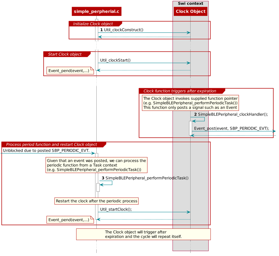
Figure 25. Triggering clock objects
Step 1 in Triggering clock objects constructs the Clock object via Util_constructClock(). After the example entered a connected state, it will then start the clock object via a Util_startClock().
// Clock instances for internal periodic events.
static Clock_Struct periodicClock;

// Create one-shot clocks for internal periodic events.
Util_constructClock(&periodicClock, SimpleBLEPeripheral_clockHandler,
    SBP_PERIODIC_EVT_PERIOD, 0, false, SBP_PERIODIC_EVT);
Step 2 in Triggering clock objects, after the Clock object’s timer expired,
it will execute SimpleBLEPeripheral_clockHandler() within a Swi context. As
this call cannot be blocked and blocks all Tasks, it is kept short by invoking
an Event_post(SBP_PERIODIC_EVT) for post processing in simple_peripheral.
static void SimpleBLEPeripheral_clockHandler(UArg arg)
{
    /* arg is passed in from Clock_construct() */
    Event_post(events, arg);
}
Attention
Clock functions must not call blocking kernel APIs or TI-RTOS driver APIs! Executing long routines will impact real-time constraints placed in high priority tasks allocated for wireless protocol stacks!
Step 3 in Triggering clock objects, the simple_peripheral task is
unblocked due the Event_post(SBP_PERIODIC_EVT), where it proceeds to invoke
the SimpleBLEPeripheral_performPeriodicTask() function. Afterwards, to
restart the periodic execution of this function, it will restart the
periodicClock Clock object.
if (events & SBP_PERIODIC_EVT)
{
  // Perform periodic application task
  SimpleBLEPeripheral_performPeriodicTask();

  Util_startClock(&periodicClock);
}
Drivers
The TI-RTOS provides a suite of CC26xx peripheral drivers that can be added to an application. The drivers provide a mechanism for the application to interface with the CC26xx onboard peripherals and communicate with external devices. These drivers make use of DriverLib to abstract register access.
There is significant documentation relating to each TI-RTOS driver located in the BLE-Stack. Refer to the BLE-Stack release notes for the specific location. This section only provides an overview of how drivers fit into the software ecosystem. For a description of available features and driver APIs, refer to the TI-RTOS API Reference.
Adding a Driver
Some of the drivers are added to the project as source files in their respective folder under the Drivers folder in the project workspace, as shown in Figure 26.
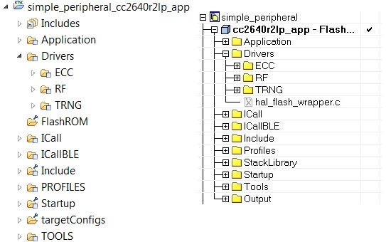
Figure 26. Drivers Folder
The driver source files can be found in their respective folder at $TI_RTOS_DRIVERS_BASE$\ti\drivers.
The $TI_RTOS_DRIVERS_BASE$ argument variable refers to the installation location and can be viewed in IAR Tools\ Configure Custom Argument Variables menu. For CCS, the corresponding path variables are defined in the Project Options\ Resource\Linked Resources, Path Variables tab.
The ECC and TRNG drivers, for example, are part of the BLE-Stack, not the TIRTOS, and they are located at <SDK_INSTALL_DIR>\source\ti\blestack\common\cc26xx\ecc and <SDK_INSTALL_DIR>\source\ti\blestack\hal\src\target\_common respectively.
To add a driver to a project, include the C and include file of the respective driver in the application file (or files) where the driver APIs are referenced.
For example, to add the PIN driver for reading or controlling an output I/O pin, add the following:
#include <ti/drivers/pin/PINCC26XX.h>
Also add the following TI-RTOS driver files to the project under the Drivers\PIN folder:
- PINCC26XX.c
- PINCC26XX.h
- PIN.h
This is described in more detail in the following sections.
Board File
The board file sets the parameters of the fixed driver configuration for a specific board configuration, such as configuring the GPIO table for the PIN driver or defining which pins are allocated to the I2C, SPI, or UART driver.
See the TI Provided Board Files section for more information on board files and how to switch between TI EMs and LPs or port to custom hardware.
Available Drivers
This section describes each available driver and provides a basic example of adding the driver to the simple_peripheral project. For more detailed information on each driver, see the TI-RTOS API Reference.
PIN
The PIN driver allows control of the I/O pins for software-controlled general-purpose I/O (GPIO) or connections to hardware peripherals. As stated in the TI Provided Board Files section, the pins must first be initialized to a safe state (configured in the board file) in main(). After this initialization, any module can use the PIN driver to configure a set of pins for use. The following is an example of configuring the simple_peripheral task to use one pin as an interrupt and another as an output, to toggle when the interrupt occurs. IOID_x pin numbers map to DIO pin numbers as referenced in CC26xx Technical Reference Manual. The following table lists pins used and their mapping on the CC2640R2F LaunchPad. These are already defined in the board file.
| Signal Name | Pin ID | CC2640R2F LaunchPad Mapping |
|---|---|---|
| CC2640R2_LAUNCHXL_PIN_RLED | IOID_6 | DIO6 (Red) |
| CC2640R2_LAUNCHXL_PIN_BTN1 | IOID_13 | DIO13 (BTN_1) |
The following simple_peripheral.c code modifications are required.
Include PIN driver files:
#include <ti/drivers/pin/PINCC26xx.h>
Declare the pin configuration table and pin state and handle variables to be used by the simple_peripheral task:
static PIN_Config SBP_configTable[] =
{
    CC2640R2_LAUNCHXL_PIN_RLED | PIN_GPIO_OUTPUT_EN | PIN_GPIO_LOW | PIN_PUSHPULL | PIN_DRVSTR_MAX,
    CC2640R2_LAUNCHXL_PIN_BTN1 | PIN_INPUT_EN | PIN_PULLUP | PIN_IRQ_BOTHEDGES | PIN_HYSTERESIS,
    PIN_TERMINATE
};

static PIN_State sbpPins;
static PIN_Handle hSbpPins;
static uint8_t LED_value = 0;
Declare the ISR to be performed in the Hwi context:
static void buttonHwiFxn(PIN_Handle hPin, PIN_Id pinId)
{
    SimpleBLEPeripheral_enqueueMsg(SBP_BTN_EVT, 0, NULL);
}
In SimpleBLEPeripheral_processAppMsg, add a case to handle the event from above, and define the event:
#define SBP_BTN_EVT

static void SimpleBLEPeripheral_processAppMsg(sbcEvt_t *pMsg)
{
    switch (pMsg->hdr.event)
    {
        case SBP_BTN_EVT:
            //toggle red LED
            if (LED_value)
            {
                PIN_setOutputValue(hSbpPins, CC2640R2_LAUNCHXL_PIN_RLED , LED_value--);
            }
            else
            {
                PIN_setOutputValue(hSbpPins, CC2640R2_LAUNCHXL_PIN_RLED, LED_value++);
            }
            break;
            //...
    }
}
Open the pins for use and configure the interrupt in simple_peripheral_init():
// Open pin structure for use
hSbpPins = PIN_open(&sbpPins, SBP_configTable);
// Register ISR
PIN_registerIntCb(hSbpPins, buttonHwiFxn);
// Configure interrupt
PIN_setConfig(hSbpPins, PIN_BM_IRQ, CC2640R2_LAUNCHXL_PIN_BTN1 | PIN_IRQ_NEGEDGE);
// Enable wakeup
PIN_setConfig(hSbpPins, PINCC26XX_BM_WaKEUP, CC2640R2_LAUNCHXL_PIN_BTN1|PINCC26XX_WAKEUP_NEGEDGE);
Compile
Download
Run
Note
Pushing the BTN-1 button on the CC2640R2F LaunchPad toggles the red LED. No debouncing is implemented.
GPIO
The GPIO module allows you to manage General Purpose I/O pins via simple and portable APIs. GPIO pin behavior is usually configured statically, but can also be configured or reconfigured at runtime.
Because of its simplicity, the GPIO driver does not follow the model of other TI-RTOS drivers in which a driver application interface has separate device-specific implementations. This difference is most apparent in the GPIOxxx_Config structure, which does not require you to specify a particular function table or object.
The following is an example of how to configure a GPIO pin to generate and interrupt and how to toggle an LED on and off within the registered interrupt callback function in Simple Peripheral.
Include GPIO driver files in simple_peripheral.c:
#include <ti/drivers/GPIO.h>
The following must be added to Board.c:
An array of GPIO_PinConfig elements that defines the initial configuration of each pin used by the application. The pin type (that is, INPUT/OUTPUT), its initial state (that is OUTPUT_HIGH or LOW), interrupt behavior (RISING/FALLING edge, etc.), and device specific pin identification are configured in each element of this array. Below is a CC26XX device specific example of the GPIO_PinConfig array:
//
// Array of Pin configurations
// NOTE: The order of the pin configurations must coincide with what was
//       defined in CC2640R2_LAUNCH.h
// NOTE: Pins not used for interrupts should be placed at the end of the
//       array.  Callback entries can be omitted from callbacks array to
//       reduce memory usage.
//
GPIO_PinConfig gpioPinConfigs[] = {
    // Input pins
    GPIOCC26XX_DIO_13 | GPIO_CFG_IN_PU | GPIO_CFG_IN_INT_RISING,  // Button 0
    GPIOCC26XX_DIO_14 | GPIO_CFG_IN_PU | GPIO_CFG_IN_INT_RISING,  // Button 1
    // Output pins
    GPIOCC26XX_DIO_07 | GPIO_CFG_OUT_STD | GPIO_CFG_OUT_STR_HIGH | GPIO_CFG_OUT_LOW,     //  Green LED
    GPIOCC26XX_DIO_06 | GPIO_CFG_OUT_STD | GPIO_CFG_OUT_STR_HIGH | GPIO_CFG_OUT_LOW,     //  Red LED
};
An array of GPIO_CallbackFxn elements that is used to store callback function pointers for GPIO pins configured with interrupts. The indexes for these array elements correspond to the pins defined in the GPIO_PinConfig array. These function pointers can be defined statically by referencing the callback function name in the array element, or dynamically, by setting the array element to NULL and using GPIO_setCallback() at runtime to plug the callback entry. Pins not used for interrupts can be omitted from the callback array to reduce memory usage (if they are placed at the end of the GPIO_PinConfig array). The callback function syntax should match the following:
void (*GPIO_CallbackFxn)(unsigned int index);
The index parameter is the same index that was passed to GPIO_setCallback(). This allows the same callback function to be used for multiple GPIO interrupts, by using the index to identify the GPIO that caused the interrupt. Below is an CC26XX device specific example of the GPIO_CallbackFxn array:
 //
 // Array of callback function pointers
 // NOTE: The order of the pin configurations must coincide with what was
 //       defined in CC2640R2_LAUNCH.h
 // NOTE: Pins not used for interrupts can be omitted from callbacks array to
 //       reduce memory usage (if placed at end of gpioPinConfigs array).
 //
 GPIO_CallbackFxn gpioCallbackFunctions[] = {
     NULL,  //  Button 0
     NULL,  //  Button 1
 };
The device specific GPIOCC26XX_Config structure tells the GPIO driver where the two aforementioned arrays are and the number of elements in each. The interrupt priority of all pins configured to generate interrupts is also specified here. Values for the interrupt priority are device-specific. You should be well-acquainted with the interrupt controller used in your device before setting this parameter to a non-default value. The sentinel value of (~0) (the default value) is used to indicate that the lowest possible priority should be used. Below is an example of an initialized GPIOCC26XX_Config structure:
 const GPIOCC26XX_Config GPIOCC26XX_config = {
      .pinConfigs = (GPIO_PinConfig *)gpioPinConfigs,
      .callbacks = (GPIO_CallbackFxn *)gpioCallbackFunctions,
      .numberOfPinConfigs = sizeof(gpioPinConfigs)/sizeof(GPIO_PinConfig),
      .numberOfCallbacks = sizeof(gpioCallbackFunctions)/sizeof(GPIO_CallbackFxn),
      .intPriority = (~0)
  };
Add the following to simple_peripheral.c:
The button callback function:
 //
 //  ======== gpioButtonFxn0 ========
 //  Callback function for the GPIO interrupt on CC2640R2_LAUNCHXL_PIN_BTN1.
 //
 void gpioButtonFxn0(unsigned int index)
 {
     // Toggle the LED
     GPIO_toggle(CC2640R2_LAUNCHXL_PIN_BTN1);
 }
Initialization and use of the GPIOs (add this to simple_peripheral_init()):
// Call GPIO driver init function
GPIO_init();

// Turn on user LED
GPIO_write(CC2640R2_LAUNCHXL_PIN_RLED, Board_GPIO_LED_ON);

// install Button callback
GPIO_setCallback(CC2640R2_LAUNCHXL_PIN_BTN1, gpioButtonFxn0);

// Enable interrupts
GPIO_enableInt(CC2640R2_LAUNCHXL_PIN_BTN1);
Compile
Download
Run
Other Drivers
The other drivers included with TI-RTOS are: UART, SPI, Crypto (AES), I2C, PDM, Power, RF, and UDMA. The stack makes use of the power, RF, and UDMA, so extra care must be taken if using these. As with the other drivers, these are well-documented, and examples are provided in the BLE-Stack.
Power Management
All power-management functionality is handled by the peripheral drivers and the Bluetooth low energy protocol stack. This feature can be enabled or disabled by including or excluding the POWER_SAVING preprocessor-defined symbol. When POWER_SAVING is enabled, the device enters and exits sleep as required for Bluetooth low energy events, peripheral events, application timers, and so forth. When POWER_SAVING is undefined, the device stays awake. See Accessing Preprocessor Symbols in CCS or Accessing Preprocessor Symbols in IAR for steps to modify preprocessor-defined symbols.
More information on power-management functionality, including the API and a sample use case for a custom UART driver, can be found in the TI-RTOS Power Management for CC26xx included in the TI-RTOS install. These APIs are required only when using a custom driver.
Also see Measuring Bluetooth Smart Power Consumption (SWRA478) for steps to analyze the system power consumption and battery life.
Memory Management
Flash
The flash is split into erasable pages of 4kB. The various sections of flash and their associate linker files are as follows.
- Simple NV (SNV) Area: used for nonvolatile memory storage by the GAP Bond Manager and also available for use by the application. See Using Simple NV for Flash Storage for configuring SNV. When configured, the SNV flash storage area is part of the stack image.
- Customer Configuration Area (CCA): the last sector of flash used to store customer-specific chip configuration (CCFG) parameters. The unused space of the CCA sector is allocated to the application project. See Customer Configuration Area.
For projects where the stack project builds a library:
- Application Image Code Space: used for the application project. This image is configured in the linker configuration file of the application: cc26xx_app.icf (IAR) and cc26xx_app.cmd (CCS).
For split image projects:
- Application Image Code Space: used for the application project. This image is configured in the linker configuration file of the application: cc26xx_app.icf (IAR) and cc26xx_app.cmd (CCS).
- Stack Image Code Space: use for the stack project. This image is configured in the linker configuration file of the stack: cc26xx_stack.icf (IAR) and cc26xx_ stack.cmd (CCS).
Flash Memory Map
This section describes the flash memory map at the system level for split image project configurations. As Figure 27. shows, the application linker file point to symbols with a solid arrow and the stack linker file point to symbols with a dashed arrow.
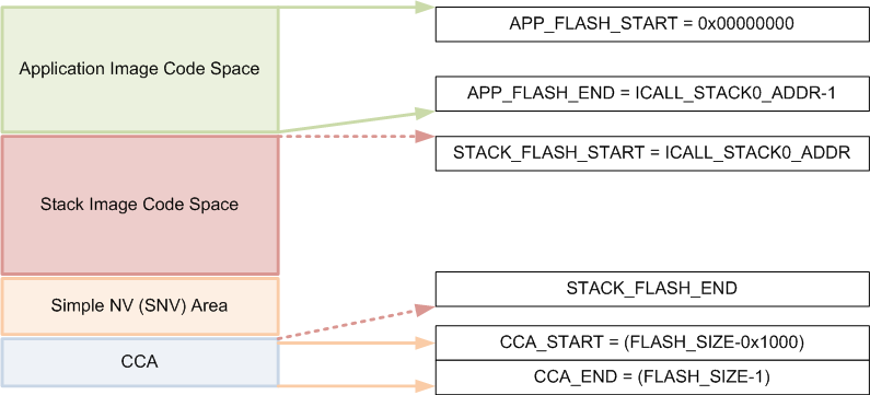
Figure 27. System Flash Map
Note
Projects that include the stack as a library, the Application Image Code Space and Stack Image Code Space are combined in the Application Image Code Space without any boundary requirements associated with split images.
Table 8. summarizes the Flash System Map definitions from Figure 27. and provides the associated linker definitions or symbols that can be found in the respective IDE linker files.
| Symbol/Region | Meaning | Project | CCS Definition | IAR Definition |
| APP_FLASH_START | Start of flash/Start of App code image | App | FLASH_APP_BASE | FLASH_START |
| APP_FLASH_END | End of App code image. (ICALL_STACK0_ADDR-1) | App | ADJ_ICALL_STACK0_START - FLASH_APP_BASE | FLASH_END |
| STACK_FLASH_START | Start of Stack code image (ICALL_STACK0_ADDR) | Stack | FLASH_START | |
| STACK_FLASH_END | End of Stack flash code image, including SNV | Stack | FLASH_SIZE - RESERVED_SIZE | FLASH_END |
| CCA sector | Last sector of flash. Contains the CCFG. | App | FLASH_LAST_PAGE | |
| CCFG region | Location in CCA where Customer Configuration (CCFG) parameters are stored | App | Last 88 bytes (sizeof(ccfg_t) of CCA | |
Application and Stack Flash Boundary
The application and stack code images are based on the common ICALL_STACK0_ADDR and ICALL_STACK0_START predefined symbols. These values define the hard-coded flash address of the entry function for the stack image: it is essentially the word-aligned flash address of the application-stack project boundary. To ensure proper linking, both the application and stack projects must use the same defined symbols. By default, the linker is configured to allocate unused flash to the application project but can be modified manually or automatically through the frontier tool. For information on using the frontier tool to configure the flash boundary address, see Frontier Tool Operation.
Using Simple NV for Flash Storage
The Simple NV (SNV) area of flash is used for storing persistent data, such as encryption keys from bonding or to store custom defined parameters. The protocol stack can be configured to reserve up to two 4kB flash pages for SNV, although valid data is only stored in one active flash page. To minimize the number of erase cycles on the flash, the SNV manager performs compaction on the flash sector (or sectors) when the sector has 80% invalidated data. A compaction is the copying of valid data to a temporary area followed by an erase of the sector where the data was previously stored. Depending on the OSAL_SNV value as described in OSAL_SNV Values, this valid data is then either placed back in the newly erased sector or remains in a new sector. The number of flash sectors allocated to SNV can be configured by setting the OSAL_SNV preprocessor symbol in the stack project. Table 9. lists the valid values that can be configured as well as the corresponding trade-offs.
| OSAL_SNV Value | Description |
| 0 | SNV is disabled. Storing of bonding keys in NV is not possible. Maximizes code space for the application and/or stack project. GAP Bond Manager must be disabled. In the Stack project, set pre- processor symbol NO_OSAL_SNV and disable GAP Bond Manager. See Stack Configurations for configuring Bluetooth low energy protocol stack features. |
| 1 (default) | One flash sector is allocated to SNV. Bonding info is stored in NV. Flash compaction uses flash cache RAM for intermediate storage, thus a power-loss during compaction results in SNV data loss. Also, due to temporarily disabling the cache, a system performance degradation may occur during the compaction. Set preprocessor symbol OSAL_SNV=1 in the Stack project. |
| 2 | Two flash sectors are allocated to SNV. Bonding information is stored in NV. SNV data is protected against power-loss during compaction. |
Other values for OSAL_SNV are invalid. Using less than the maximum value has the net effect of allocating more code space to the application or stack project. SNV can be read from or written to using the following APIs.
uint8 osal_snv_read( osalSnvId_t id, osalSnvLen_t len, void *pBuf)
| Read data from NV | |
| Parameters | id - valid NV item len - length of data to read pBuf - pointer to buffer to store data read |
| Returns | SUCCESS: NV item read successfully NV_OPER_FAILED: failure reading NV item |
uint8 osal_snv_write( osalSnvId_t id, osalSnvLen_t len, void *pBuf)
| Write data to NV | |
| Parameters | id - valid NV item len - length of data to write pBuf - pointer to buffer containing data to be written. All contents are updated at once. |
| Returns | SUCCESS: NV item write successfully NV_OPER_FAILED: failure writing NV item |
Because SNV is shared with other modules in BLE-Stack 3.00.01 such as the GAP Bond Manager, carefully manage the NV item IDs. By default, the IDs available to the customer are defined in bcomdef.h as shown in Listing 26.
1 2 3 4 5 6 7 8 9 10 11 12 13 14 15 16 17 | // Device NV Items - Range 0 - 0x1F
#define BLE_NVID_IRK 0x02 //!< The Device's IRK
#define BLE_NVID_CSRK 0x03 //!< The Device's CSRK
#define BLE_NVID_SIGNCOUNTER 0x04 //!< The Device's Sign Counter
#define BLE_LRU_BOND_LIST 0x05 //!< The Device's order of bond indexes in least recently used order
// Bonding NV Items - Range 0x20 - 0x5F - This allows for 10 bondings
#define BLE_NVID_GAP_BOND_START 0x20 //!< Start of the GAP Bond Manager's NV IDs
#define BLE_NVID_GAP_BOND_END 0x5f //!< End of the GAP Bond Manager's NV IDs Range
// GATT Configuration NV Items - Range 0x70 - 0x79 - This must match the number of Bonding entries
#define BLE_NVID_GATT_CFG_START 0x70 //!< Start of the GATT Configuration NV IDs
#define BLE_NVID_GATT_CFG_END 0x79 //!< End of the GATT Configuration NV IDs
// Customer NV Items - Range 0x80 - 0x8F - This must match the number of Bonding entries
#define BLE_NVID_CUST_START 0x80 //!< Start of the Customer's NV IDs
#define BLE_NVID_CUST_END 0x8F //!< End of the Customer's NV IDs
|
Listing 27. shows how to read and write an array of bytes from SNV flash:
/*********************************************************************
* GLOBAL VARIABLES
*/
#define BUF_LEN 4
#define SNV_ID_APP 0x80
uint8 buf[BUF_LEN] ={0,};

static void SimpleBLEPeripheral_taskFxn(UArg a0, UArg a1)
{
  // Initialize application
  SimpleBLEPeripheral_init();
  uint8 status = SUCCESS;

  status = osal_snv_read(SNV_ID_APP, BUF_LEN, (uint8 *)buf);
  if(status != SUCCESS)
  {
    Display_print1(dispHandle, 0, 0, "SNV READ FAIL: %d", status);
    //Write first time to initialize SNV ID
    osal_snv_write(SNV_ID_APP, BUF_LEN, (uint8 *)buf);
  }

  //Increment first element of array and write to SNV flash
  buf[0]++;
  status = osal_snv_write(SNV_ID_APP, BUF_LEN, (uint8 *)buf);
  if(status != SUCCESS)
  {
    Display_print1(dispHandle, 0, 0, "SNV WRITE FAIL: %d", status);
  }
  else
  {
    Display_print1(dispHandle, 0, 0, "Num of Resets: %d", buf[0]);
  }

  // Application main loop
  for (;;)
  {
  //...
  }
}
No prior initialization of a NV item ID is required; the OSAL SNV manager initializes the NV ID when first accessed by a successful osal_snv_write() call.
When reading or writing large amounts of data to SNV, TI recommends placing the read/write data in statically (linker) allocated arrays or buffers allocated from the heap. Placing large amounts of data in local arrays may result in a task stack overflow.
By default, osalSnvId_t and osalSnvLen_t are type defined as uint8. To use uint16-type definitions, define the preprocessor symbol OSAL_SNV_UINT16_ID in both the application and stack projects.
Using osal_snv_read and osal_snv_write is only permitted from within a task context. Calling this API is not possible from within Swis or Hwis.
Customer Configuration Area
The Customer Configuration Area (CCA) occupies the last page of flash and lets a customer configure various chip and system parameters in the Customer Configuration (CCFG) table . The CCFG table is defined in ccfg_app_ble.c, which can be found in the Startup folder of the application project. The last 88 (sizeof(ccfg_t)) bytes of the CCA sector are reserved by the system for the CCFG table. By default, the linker allocates the unused flash of the CCA sector to the application image for code and data use. The linker can be modified to reserve the entire sector for customer parameter data (for example, board serial number and other identity parameters).
The CCA region is defined linker file of the application by the FLASH_LAST_PAGE symbol. Placement is based on the IDE:
For CCS:
MEMORY
{
    ...
    // CCFG Page, contains .ccfg code section and some application code.
    FLASH_LAST_PAGE (RX) :  origin = FLASH_LAST_PAGE_START, length = FLASH_PAGE_LEN
    ...
}

SECTIONS
{
    ...
    .ccfg           :   >  FLASH_LAST_PAGE (HIGH)
    ...
}
For IAR:
////////////////////////////////////////////////////////////////////////////////
// Memory Regions
////////////////////////////////////////////////////////////////////////////////
...
define region FLASH_LAST_PAGE       = mem:[from(FLASH_SIZE - PAGE_SIZE) to FLASH_SIZE-1];
...
////////////////////////////////////////////////////////////////////////////////
...
// CCFG
place at end of FLASH_LAST_PAGE { readonly section .ccfg };
keep { section .ccfg }
See the CC26xx Technical Reference Manual for details on CCFG fields and related configuration options, including how to set the CCFG to disable access to internal flash memory contents.
RAM
Similar to flash, the RAM is shared between the application and stack projects. The RAM sections are configured in their respective linker files.
- Application Image: RAM space for the application and shared heaps. This image is configured in the linker configuration file of the application: cc26xx_app.icf (IAR) and cc26xx_app.cmd (CCS).
- Stack Image: RAM space for the .bss and .data sections of the stack. This image is configured in the linker configuration file of the stack: cc26xx_stack.icf (IAR) and cc26xx_stack.cmd (CCS).
RAM Memory Map
System Memory Map shows the system memory map for the default simple_peripheral project. This is a summary and the exact memory placement for a given compilation can be found in the simple_peripheral_app.map and simple_peripheral_stack.map files in the output folder in IAR or the FlashROM folder in CCS. In Check System Flash and RAM Usage With Map File, the application linker file contains symbols pointed with a solid arrow and the stack linker file contains symbols pointed with a dashed arrow.
System Memory Map

Figure 28. System Memory Map
Application and Stack RAM Boundary
The application and stack RAM memory maps are based on the common ICALL_RAM0_START defined symbol. This value defines the hard-coded RAM boundary for the end of the RAM space of the application and the start of the image of the stack .BSS and .DATA sections. Unlike the flash boundary, elements of the stack project (such as task stacks and heaps) are allocated in the application project. To ensure proper linking, both the application and stack projects must use the same ICALL_RAM0_START value. By default, ICALL_RAM0_START is configured to allocate unused RAM to the application project through the frontier tool. For information on using the frontier tool to configure the RAM boundary address, see Frontier Tool Operation.
System Stack
Besides the RTOS and ICall heaps, consider other sections of memory. As described in Tasks, each task has its own runtime stack for context switching. Another runtime stack is used by the RTOS for main(), HWIs, and SWIs. This system stack is allocated in the application linker file to be placed at the end of the RAM of the application.
For IAR, this RTOS system stack is defined by the CSTACK symbol:
////////////////////////////////////////////////////////////////////////////////
// Stack
define symbol STACK_SIZE            = 0x400;
define symbol STACK_START           = RAM_END + 1;
define symbol STACK_END             = STACK_START - STACK_SIZE;
//
define symbol STACK_TOP             = RAM_END + 1;
export symbol STACK_TOP;

// Runtime Stack
define block CSTACK with alignment = 8, size = STACK_SIZE { section .stack };
place at end of RAM { block CSTACK };
In IAR, to change the size of the CSTACK, adjust the STACK_SIZE symbol value in the linker file of the application.
For CCS, the RTOS system stack is defined by the Program.stack parameter in the appBLE.cfg RTOS configuration file:
/* main() and Hwi, Swi stack size */
Program.stack = 1024;
and placed by the linker in the RAM space of the application:
/* Create global constant that points to top of stack */
/* CCS: Change stack size under Project Properties */
__STACK_TOP = __stack + __STACK_SIZE;
Dynamic Memory Allocation
The system uses two heaps for dynamic memory allocation. The application designer must understand the use of each heap to maximize the use of available memory.
The RTOS is configured with a small heap in the app_ble.cfg RTOS configuration file:
var HeapMem = xdc.useModule('xdc.runtime.HeapMem');

BIOS.heapSize = 1668;
This heap (HeapMem) is used to initialize RTOS objects and allocate the task runtime stack of the Bluetooth low energy protocol stack. TI chose this size of this heap to meet the system initialization requirements. Due to the small size of this heap, TI does not recommend allocating memory from the RTOS heap for general application use. For more information on the TI-RTOS heap configuration, see the Heap Implementations section of the TI-RTOS SYS/BIOS Kernel User’s Guide.
The application must use a separate heap. The ICall module uses an area of application RAM which can be used by the various tasks. The size of this ICall heap is defined by the HEAPMGR_SIZE preprocessor definition in the application project. Using a non-zero value sets the ICall heap to the specified value, while a HEAPMGR_SIZE value of zero (0) auto sizes the heap to a size equal to the amount of available free RAM not allocated by the linker. By default, the simple_peripheral project uses the auto size feature. Although the ICall heap is defined in the application project, this heap is also shared with the Bluetooth low energy protocol stack. APIs that allocate memory (such as GATT_bm_alloc()) allocate memory from the ICall heap.
To profile the amount of ICall heap used, define the HEAPMGR_METRICS preprocessor symbol in the application project. Refer to Profiling the ICall Heap Manager (heapmgr.h) to determine the size of the ICall heap when the auto heap size feature is enabled.
Note
The auto heap size feature does not determine the amount of heap needed for the application. The system designer must ensure that the heap has the required space to meet the application’s runtime memory requirements.
The following is an example of dynamically allocating a variable length (n) array using the ICall heap:
//define pointer
uint8_t *pArray;
// Create dynamic pointer to array.
if (pArray = (uint8_t*)ICall_malloc(n*sizeof(uint8_t)))
{
//fill up array
}
else
{
//not able to allocate
}
The following is an example of freeing the previous array:
ICall_free(pMsg->payload);
Cache/GPRAM
The cache is an 8 KB section of the device’s RAM reserved for the processor. The cache module temporarily stores data that has been read from the Flash, so that frequently used data is not fetched from Flash on each access. This reduces CPU wait-states and saves power. When the cache is not used, it is not powered. This is true for Standby and Idle states where the cache is not in use.
Using the Cache as RAM
If your application needs more memory, or if you need more space in SRAM, the cache can be re-purposed as RAM. This will allow the linker to store parts of the compiled application in this section of the RAM. This section will be referred to as the general purpose RAM (GPRAM). This will cause the program to run at a slightly reduced speed, and it will increase the device power consumption in sleep. This is because the GPRAM, contrary to a cache, will have to be powered even when the device is sleeping. The current consumption in standby mode with and without cache retained is listed in the CC2640R2F datasheet.
With the cache re-purposed as RAM, the program will run at a slightly decreased speed. This will cause the device to spend more time when active, which again will give a higher power consumption. How this will affect the device power consumption will depend on application. For some applications the added power consumption will be very small, but for processing intensive application it will be slightly higher. Please verify your application current consumption by using the method described in Measuring Bluetooth Low Energy Power Consumption Application Report (SWRA478).
In order to enable using the cache as RAM, two things need to be done. Firstly, the program must be told to retain the cache/GPRAM when it’s being used. Secondly, the linker must be told to allocate the memory region used as cache to GPRAM, and what parts of code to store in the GPRAM. This is done in the linker command/configuration file. The syntax for the linker command/configuration file is slightly different in CCS and IAR. To read more about the CCS linker command file, see the wiki article Linker Command File Primer. To read more about the IAR linker, see IAR C/C++ Development Guide.
Some of the example projects found in the BLE-Stack 3.00.01 have a Build Configuration that allows using the cache as RAM. This is true for e.g. the multi_role project. In this case, cache as RAM can be enabled by choosing that build configuration. In CCS: Project -> Build Configurations -> Set Active -> FlashROM-CacheAsRAM. In IAR: Project -> Edit Configurations -> FlashROM-CacheAsRAM.
Warning
When changing the build configuration of a project, the project properties/options may reset. Please make sure to make changes to the project predefines etc., after changing the build configuration.
If you want to use the cache as RAM in a project which does not have the CacheAsRAM build configuration, follow these steps:
Note
The steps will be different for CCS users and IAR users. The steps will also differ depending on what example project your project is based on. For the example projects found in the
blestackfolder, only step 1-5 will be required.1. In the ccfg file, (called
app_ble_ccfg.corccfg.c), include the following before#include <startup_files/ccfg.c>:#ifdef CACHE_AS_RAM #define SET_CCFG_SIZE_AND_DIS_FLAGS_DIS_GPRAM 0x0 /* Enable GPRAM */ #endif //CACHE_AS_RAM #include <startup_files/ccfg.c>
- In
main(), add the following code:#ifdef CACHE_AS_RAM // retain cache during standby Power_setConstraint(PowerCC26XX_SB_VIMS_CACHE_RETAIN); Power_setConstraint(PowerCC26XX_NEED_FLASH_IN_IDLE); #else // Enable iCache pre-fetching VIMSConfigure(VIMS_BASE, TRUE, TRUE); // Enable cache VIMSModeSet(VIMS_BASE, VIMS_MODE_ENABLED); #endif //CACHE_AS_RAMWarning
Please make sure your program is not using VIMS while using cache as RAM.
In the same file, include the following files: (In
blestackprojects, these are already included in main.c.)/* Power Driver */ #include <ti/drivers/Power.h> #include <ti/drivers/power/PowerCC26XX.h> /* Header files required to enable instruction fetch cache */ #include <ti/devices/cc26x0r2/inc/hw_memmap.h> #include <ti/devices/cc26x0r2/driverlib/vims.h>3. Go to the compiler predefines and add
CACHE_AS_RAM. For the example projects from theblestackfolder, this define will bring changes to the executed code in the following files:
ble_user_config.cmain.c4. Go to the linker predefines and add
CACHE_AS_RAM=1. This define will bring changes to the executed code incc26xx_app.cmd/cc26xx_app.icf.Note
For more information on how to edit compiler and linker symbol settings please see the following sections:
5. If your project is based on a
blestackproject, this will move.bssfrom SRAM to GPRAM. Other objects can also be moved. See Using the AUX RAM as RAM for an example of this. Rebuild and flash your app project. View the .map file to see what parts of the device memory is occupied. (Alternatively, in CCS: View -> Memory Allocation.)6. If your project is not based on a
blestackproject, there are still changes that need to be made in order to use the cache as GPRAM. If your project is using the radio, add0x00018063to the radio overrides.7. The GPRAM memory area must be defined in the linker command file. This syntax is different for the CCS and IAR linker. IAR specific instructions will follow the CCS specific instructions.
In CCS, the linker command file ends with
.cmd(e.g.CC2640R2_LAUNCHXL_TIRTOS.cmd)./******************************************************************************* * Memory Sizes */ #define FLASH_BASE 0x00000000 #define GPRAM_BASE 0x11000000 #define RAM_BASE 0x20000000 #define ROM_BASE 0x10000000 #ifdef CC26X0ROM #define FLASH_SIZE 0x00020000 #define GPRAM_SIZE 0x00002000 #define RAM_SIZE 0x00005000 #define ROM_SIZE 0x0001C000 #endif /* CC26X0ROM *//******************************************************************************* * GPRAM */ #ifdef CACHE_AS_RAM #define GPRAM_START GPRAM_BASE #define GPRAM_END (GPRAM_START + GPRAM_SIZE - 1) #endif /* CACHE_AS_RAM */#ifdef CACHE_AS_RAM GPRAM(RWX) : origin = GPRAM_APP_BASE, length = GPRAM_SIZE #endif /* CACHE_AS_RAM */#ifdef CACHE_AS_RAM .bss : > GPRAM #endif /* CACHE_AS_RAM */ #ifndef CACHE_AS_RAM .bss : > SRAM #endif /* CACHE_AS_RAM */Rebuild your application. This will move
.bssfrom SRAM to GPRAM. Other objects can also be moved. See Using the AUX RAM as RAM for an example of this.
- In IAR, the linker configuration file ends witth
.icf(e.g.CC2640R2_LAUNCHXL_TIRTOS.icf).////////////////////////////////////////////////////////////////////////////// // GPRAM // if ( isdefinedsymbol(CACHE_AS_RAM) ) { define symbol GPRAM_START = 0x11000000; define symbol GPRAM_SIZE = 8096; define symbol GPRAM_END = GPRAM_START + GPRAM_SIZE; }if ( isdefinedsymbol(CACHE_AS_RAM) ) { define region GPRAM = mem:[from GPRAM_START to GPRAM_END]; }if ( isdefinedsymbol(CACHE_AS_RAM) ) { // GPRAM define block GPDATA { section .bss }; place in GPRAM { block GPDATA }; }Rebuild your application. This will move
.bssfrom SRAM to GPRAM. Other objects can also be moved. See Using the AUX RAM as RAM for an example of this.
AUX RAM
The AUX RAM is a 2 KB memory area belonging to the Sensor Controller. If you application does not use the Sensor Controller, you can use this memory as RAM for your application. However, access to this memory is significantly slower than access to the SRAM. This may lead to increased power consumption and slower program execution.
Using the AUX RAM as RAM
In order to use the AUX RAM with you application, follow these steps (CCS is first described, then IAR).
1. Make a new define in the linker command file predefines: In CCS;
Project -> Properties -> ARM Linker -> Advanced Options -> Command
File Preprocessing. In IAR; Options -> Linker -> Config. Add
AUX_AS_RAM=1.
2. The linker command/configuration files are somewhat different from CCS to IAR. The instructions for altering the linker configuration file in IAR follows the CCS specific explanations.
In the linker command file
cc26xx_app.cmd, define the AUX_RAM memory area:#ifdef AUX_AS_RAM #define AUX_RAM_BASE 0x400E0000 #define AUX_RAM_SIZE 0x800 #endif /* AUX_AS_RAM */
Create a AUX_RAM memory section in
MEMORY{}
#ifdef AUX_AS_RAM
AUX_RAM (RWX) : origin = AUX_RAM_BASE, length = AUX_RAM_SIZE
#endif /* AUX_AS_RAM */
Add sections of memory or code to AUX_RAM in
SECTIONS{}#ifdef AUX_AS_RAM reorganized_into_auxram { simple_peripheral.obj(.data) devinfoservice.obj(.data) simple_gatt_profile.obj(.data) icall.obj(.data) board.obj(.bss) } > AUX_RAM #endif/* AUX_AS_RAM */
The .obj files are listed in the FlashROM folder of the app project. They are also listed with size in the .map file. A detailed description of the linker command file and memory sections is given in the wiki article Linker Command File Primer.
If you want more control over what is stored in AUX_RAM, individual
variables can be stored there with the #pragma DATA_SECTION command.
Please note that this is only possible for global variables.
// Display Interface #pragma DATA_SECTION(dispHandle, "my_section") Display_Handle dispHandle = NULL;#ifdef AUX_AS_RAM reorganized_into_auxram { simple_peripheral.obj(my_section) } > AUX_RAM #endif /* AUX_AS_RAM */
Warning
When making alterations only to the linker command file, please make sure to press Rebuild, not just Build. (CCS will not recognize that you have made changes to the project before you press Rebuild.)
- For IAR, open the linker configuration file
cc26xx_app.icf. UnderMemory Definitions, add
////////////////////////////////////////////////////////////////////////////////
// AUX_RAM
//
if ( isdefinedsymbol(AUX_AS_RAM) )
{
  define symbol AUX_RAM_START        = 0x400E0000;
  define symbol AUX_RAM_SIZE         = 0x800;
  define symbol AUX_RAM_END          = AUX_RAM_START + AUX_RAM_SIZE;
}
Under
Memory Regions, addif ( isdefinedsymbol(AUX_AS_RAM) ) { define region AUX_RAM = mem:[from AUX_RAM_START to AUX_RAM_END]; }Under
Memory Placement, addif ( isdefinedsymbol(AUX_AS_RAM) ) { // AUX_RAM define block AUXDATA { section .data object simple_peripheral.o, section .data object devinfoservice.o, section .data object simple_gatt_profile, section .data object icall.o, section .data object board.o}; place in AUX_RAM { block AUXDATA }; }
The .o-files are listed in the .map file. For more information on the linker configuration file, please see IAR C/C++ Development Guide.
If you want more control over what is stored in AUX_RAM, individual
variables can be stored there with the #pragma location command.
Please note that this is only possible for global variables.
Listing 40. Move the global display handle variable into a new Cache RAM section calledmy_section.¶// Display Interface #pragma location="my_section" Display_Handle dispHandle = NULL;if ( isdefinedsymbol(AUX_AS_RAM) ) { // AUX_RAM define block AUXDATA { section my_section object simple_peripheral.o }; place in AUX_RAM { block AUXDATA }; }
Frontier Tool
The frontier tool is a utility to automatically adjust the respective RAM and flash boundary address symbols shared between the application and stack projects built as split images. Project where the application consumes the stack as a library do not require the use of the Frontier Tool.
Frontier runs as a post-build step of the stack project, and adjusts the respective RAM and flash boundaries based on analysis of the stack linker and map files. No project files are modified by the frontier tool. The frontier tool does not modify any source code or perform any compiler or linker optimization; the tool adjusts and updates the respective flash and RAM boundary addresses, located in the compiler and linker configuration files used by the application and stack projects.
The frontier tool is installed to the following path within the SDK: <SDK_INSTALL_DIR>\examples\rtos\CC2640R2_LAUNCHXL\blestack\tools\frontier\frontier.exe
The python source for this tool is also included.
Table 10. shows the boundary address symbols updated by the frontier tool.
| Boundary Address Symbol | Definition |
|---|---|
| ICALL_STACK0_START | Boundary flash address between application and stack images. Represents the end of the application image and the beginning of the stack image. |
| ICALL_STACK0_ADDR | Stack entry address (flash) |
| ICALL_RAM0_START | Boundary RAM address between application and stack images. Represents the end of the application RAM and the beginning of the stack RAM. |
All sample application projects are, by default, configured to use the frontier tool; thus, no user configuration of the frontier tool is required. The boundary files may be updated when the stack configuration is changed, or when any files are updated in the stack project that result in a change in the size of the stack image. It is therefore required to rebuild the application project anytime the stack project is built.
Note
The frontier tool replaces the boundary tool used in earlier SDKs.
Frontier Tool Operation
The frontier tool (frontier.exe) is invoked as a CCS or IAR IDE post-build operation of the stack project. If an adjustment to the RAM or flash boundary is required, the frontier tool updates the boundary linker configuration and C definition files listed below. To incorporate the updated configuration values, perform a Project -> Rebuild All on the application project. The stack project must build and link correctly before the application can be rebuilt.
Each project in the SDK has a set of configuration files that the linker and compiler of the IDE use to set or adjust the respective flash and RAM values. These configuration files are shared between the application and stack workspaces, and are stored at the following location:
<SDK_INSTALL_DIR>\examples\rtos\<EVAL_BOARD>\blestack\<PROJECT>\tirtos\<IDE>\config
Where <EVAL_BOARD> is the evaluation platform, <PROJECT> is the sample application (for example, simple_peripheral), and <IDE> is either IAR or CCS.
For example, the simple_peripheral sample application running on the CC2640R2F LaunchPad, the boundary config files are located at the following paths:
CCS: <SDK_INSTALL_DIR>\examples\rtos\CC2640R2_LAUNCHXL\blestack\simple_peripheral\tirtos\ccs\config
IAR: <SDK_INSTALL_DIR>\examples\rtos\CC2640R2_LAUNCHXL\blestack\simple_peripheral\tirtos\iar\config
The following are the boundary config files:
- Boundary linker configuration file: iar_boundary.xcl [IAR] or ccs_linker_defines.cmd [CCS]. Defines the boundary addresses for the linker. This file is in the TOOLS IDE folder and is updated by the frontier tool when an adjustment is required.
- Boundary C definition file: iar_boundary.bdef [IAR] or ccs_compiler_defines.bcfg [CCS]. Defines the boundary addresses for the compiler. This file is in the TOOLS IDE folder and is updated by the frontier tool when an adjustment is required.
Note
The values in the boundary linker configuration file and the boundary C definition file must match.