Texas Instruments System Controller Interface (TISCI)
Communicating with the System Controller Entity
Texas Instruments’ System Control Interface (TISCI) defines the communication protocol between various processing entities to the System Control Entity on TI SoCs. This is a set of message formats and sequence of operations required to communicate and get system services processed from the System Control Entity in the SoC.
The block diagram of the different Hosts communicating with the System Firmware or System Controller Entity is as shown below.
A host uses multiple threads to communicate with the System Firmware. On the K3 devices the following threads are used for each host:
- High priority thread write to System Firmware
- Low priority thread write to System Firmware
- Response thread read from System Firmware
- Notification thread read from System Firmware
- Notification Response thread write to System Firmware
On the K3-Lite Devices the following threads are used for each host:
- Low priority thread write to System Firmware
- Response thread read from System Firmware
Each physical processor in the SoC has the ability to operate in different modes like privileged and non-privileged, secure or non secure. The definition of host goes beyond the physical processor and also differentiates the mode in which the processor operates. Refer Enumeration of Host IDs for the list of hosts supported in the AM65XX device. Similar Host ID list is available for other devices.
Note
The majority of users will not need to use TISCI since they will use Processor SDK Linux/RTOS services. For users that do not use Processor SDK, TISCI is provided to access system services.
An example of when you may need to make use of TISCI is for the implementation of another operating system. Users can look at the integration in Processor SDK for an example.
On devices with distributed TIFS and DM services across multiple cores, the interaction between the hosts and the security and device manager is as below:
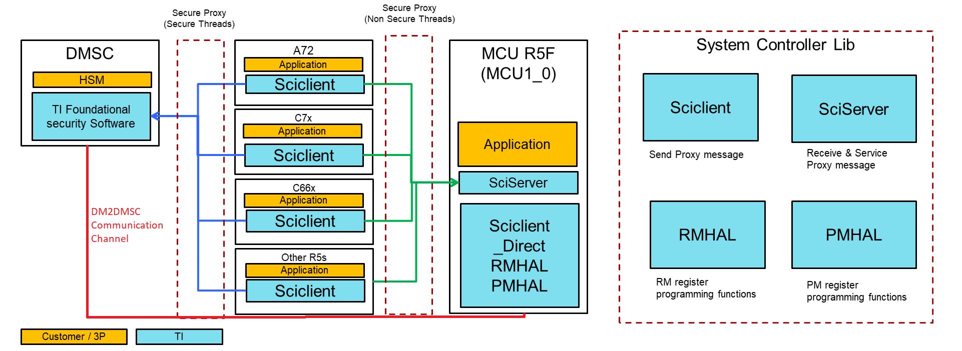
Fig. 4 Software on different cores and secure proxy communication channels
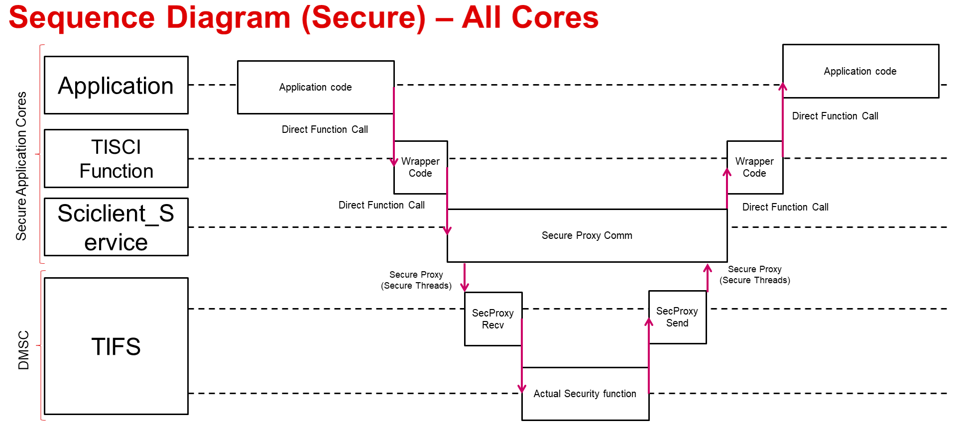
The communication mechanism for different cores is as below
For secure cores the communication mechanism is as below:
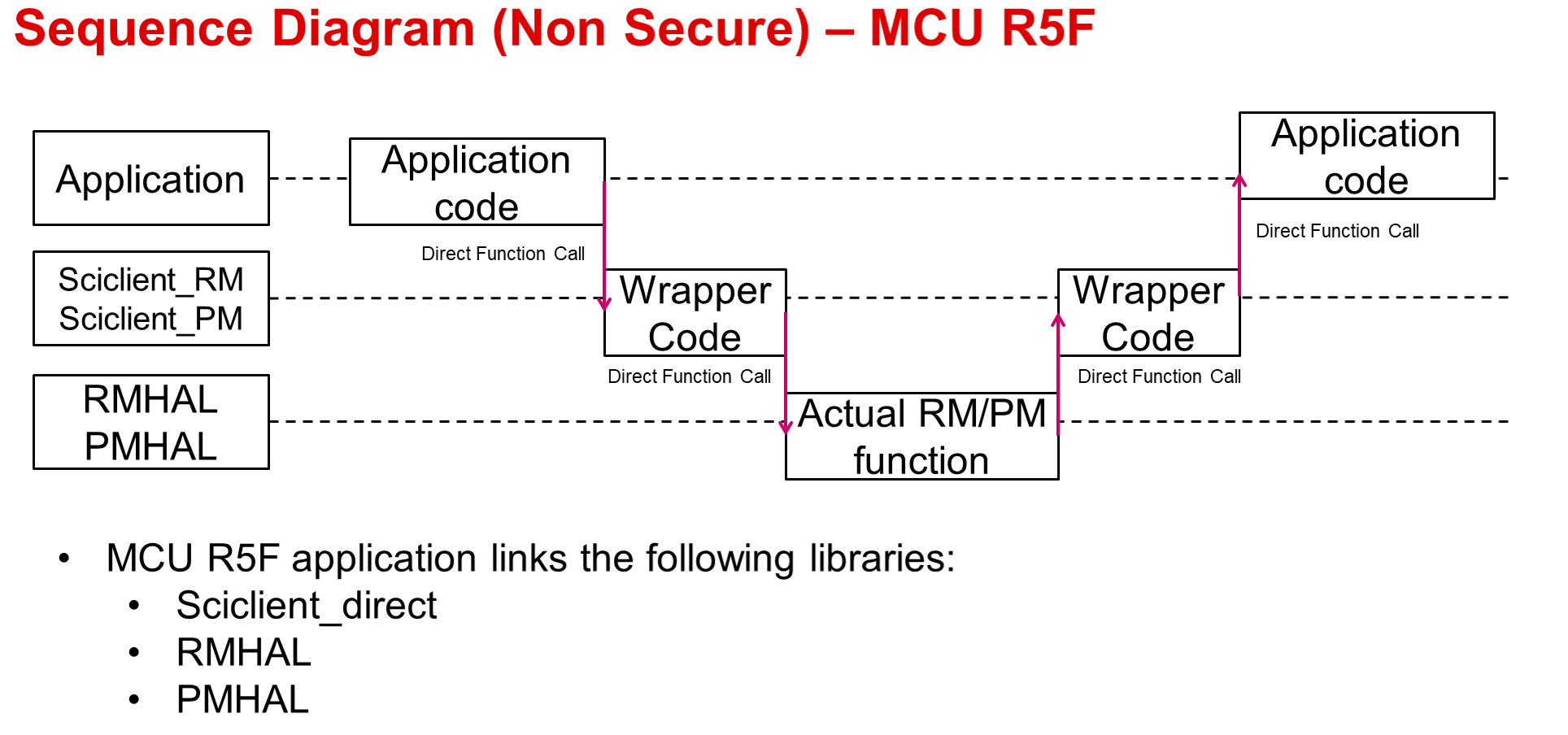
For messages running from MCU R5F the communication mechanism is as below:
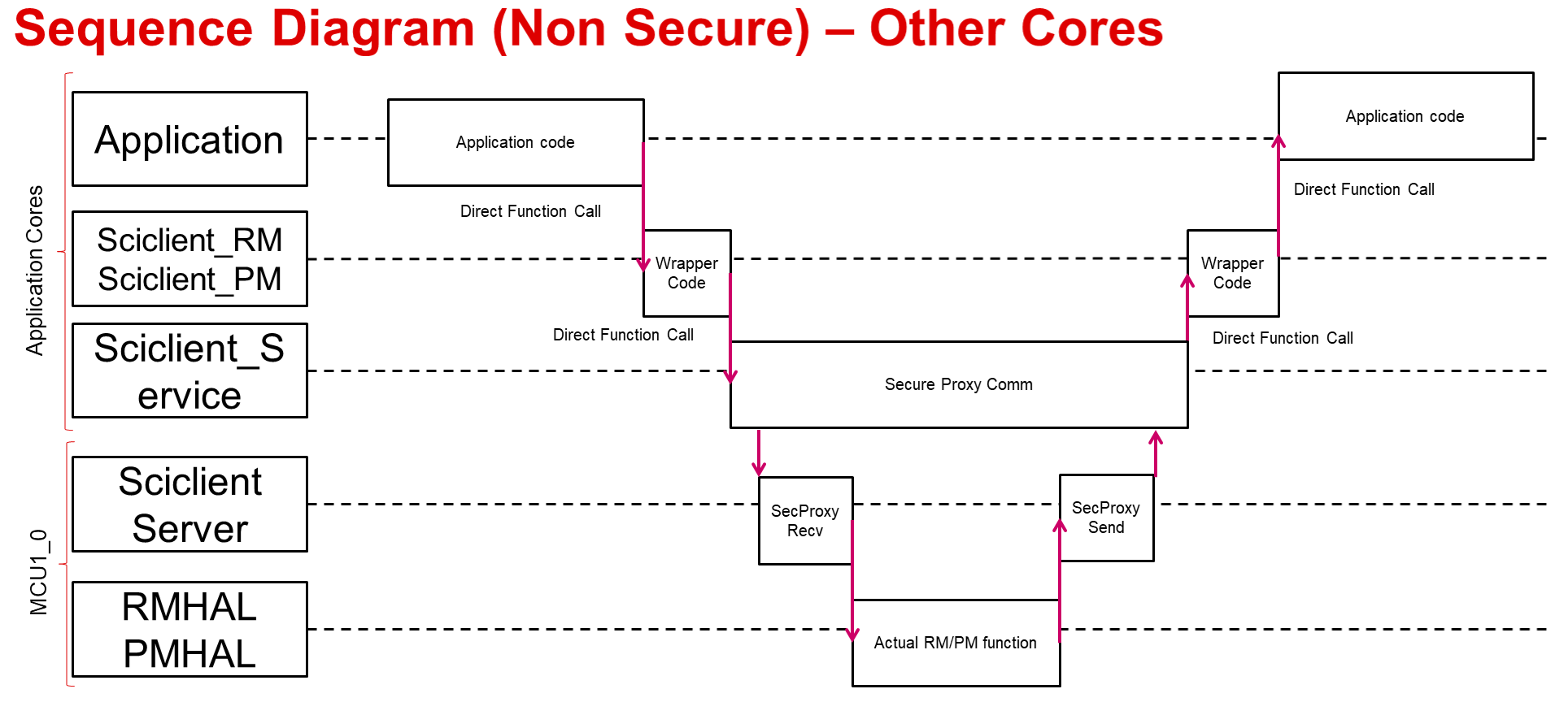
For messages running from other non-secure cores the communication mechanism is as below:
The following subsections gives a high level overview of the different APIs and functions available via the TISCI interface.
Power and Clock Management
Public APIs are provided to perform:
- Device Management: Enable and release a module
- This configures both power and clock details for the module and keeps track of its usage.
- Clock Management: Control the frequency of the clock to a module.
- Device Reset Control
Refer Power Management (PM) for more details.
Resource Management
Public APIs are provided to:
- Manage DMA/Navigator Resources
- UDMAP/PKTDMA/BCDMA
- Ring Accelerator
- PSI-L
- Proxy
- Program interrupts (interrupt aggregators and routers) both at SoC and subsystem (DMA/Navigator) level
Refer Resource Management (RM) for more details.
Foundational Security Management
Public APIs are provided to directly configure these features following polices and root of trust:
- Firewall
- Additional layer of access control beyond MMU/MPU located at each destination/slave interface to control memory and register access
- SA2-UL Security Contexts
- Contains actual keys for crypto accelerator
APIs are also provided to authenticate and/or decrypt blobs in memory.
Refer Secure Management for more details.
TISCI General Messages
In addition to the above messages, the TISCI also supports certain general messages. Details regarding the same are available at General. Refer to this section in order to understand the generic message header format for each of the power management, resource management and security management messages.
TISCI Generic Messaging Header
All messages are prefixed by a header. This header is always present for transmit or receive messages. The format is as follows:
struct tisci_header
Header that prefixes all TISCI messages.
| Parameter | Type | Description |
|---|---|---|
| type | u16 | Type of message identified by a TISCI_MSG_* ID |
| host | u8 | Host of the message. |
| seq | u8 | Message identifier indicating a transfer sequence. |
| flags | u32 | TISCI_MSG_FLAG_* for the message |
The host field must contain a value from the
Valid SoC Host ID List
that corresponds to the host actually sending the message as identified.
The seq field is a sequence number that will be returned back to the user
for the response corresponding to the message. It is up to the user to define
seq in whatever way they choose. The primary intent of this field is to
allow for the queueing of multiple messages on different priority queues while
still being able to identify the response to the specific message that was
transmitted.
The following generic flags are available for the flags field:
Request flags
TISCI_MSG_FLAG_RESERVED0 BIT(0)
This flag is reserved and not to be used.
TISCI_MSG_FLAG_AOP BIT(1)
ACK on Processed: Send a response to a message after it has been processed with TISCI_MSG_FLAG_ACK set if the processing succeeded, or a NAK otherwise. This response contains the complete response to the message with the result of the actual action that was requested.
TISCI_MSG_FLAG_REQ_NOTFWD2DM BIT(3)
Indicates that this request should not be forwarded to DM
Warning
It is critical that the TISCI_MSG_FLAG_AOP is set (often TISCI_MSG_FLAG_AOP is the desired option) if a proper response is required, as without any ACK requested no response will be sent at all, even in the case of failure. If no response is acceptable this warning can be disregarded.
Response flags
TISCI_MSG_FLAG_ACK BIT(1)
Response flag for a message that indicates success. If this flag is NOT set then that is to be interpreted as a NAK.
Secure Messaging Header
All messages received by System Firmware through a secure transport must include a “Secure Messaging Header” in addition to the “Generic Messaging Header”. The “Secure Messaging Header” allows System Firmware to verify that the message has been received intact. The format is as follows.
Note
The Secure Messaging Header is only required when sending messages over secure transport. Messages sent over non-secure transport must not contain the secure messaging header.
struct tisci_sec_header
Header that prefixes all TISCI messages sent via secure transport.
| Parameter | Type | Description |
|---|---|---|
| integ_check | u16 | This field should always be initialized to zero on GP devices. The mechanism to calculate the integrity check for HS devices is under definition. |
| rsvd | u16 | Reserved field for future use. Initialize to zero. |
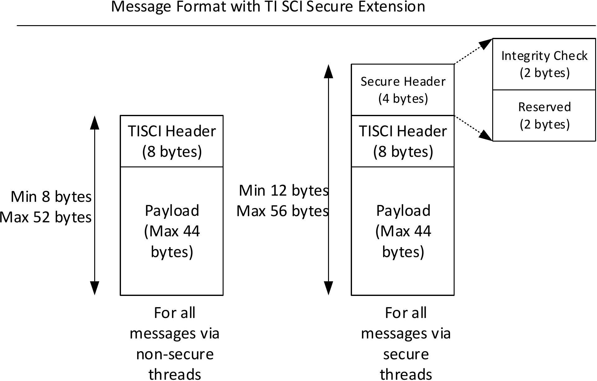
Fig. 5 Secure Messaging Header format
- The Secure header is mandatory for all messages that are received via secure transports. In AM6x devices, secure transport is a secure proxy thread that has been marked as secure.
- The secure header is placed before a TI SCI message. We chose this header placement as it is akin to wrapping a TISCI message in a secure header. Processing of the secure header can happen in a separate layer on both the transmitter and the receiver. Rest of the code can be unaware of the secure header.
- The first two bytes of the secure header are used for storing the integrity check field.
- The next two bytes of the secure header are reserved for future use and are initialized to zero.
Secure header in the request path
The maximum length of the data that can be sent is 56 bytes. Of these 8 bytes are taken up by the standard TISCI header, 4 bytes by the secure header leaving 44 bytes for the payload.
The user is expected to
- Prepare the TISCI message as usual.
- Prepend the secure header initialized to zero. In the memory layout, the secure header should be followed by the TISCI header. TISCI header should be followed by the payload.
- Set the integrity check field to zero. The integrity check field is reserved for future use. See Secure header integrity check calculation for details.
- Send the message to System Firmware via the chosen transport.
Secure header in the response path
In the response path, System Firmware populates the integrity check field with zero for all responses via a secure transport. The integrity check field is reserved for future use and does not need to be verified by the message sender.
Secure header on a GP device vs a HS device
GP Device
The Secure Messaging header is not processed by System Firmware on a GP device. The host sending the TISCI request should populate the Secure Messaging Header with zeros.
To maintain API compatibility between GP and HS devices, all messages sent or received from System Firmware via a secure transport must include the Secure Messaging Header.
HS Device
The Secure Messaging header is not processed by System Firmware on HS devices. The integrity check field is reserved for future use. The host sending the TISCI request should populate the Secure Messaging Header with zeros.
To maintain API compatibility, all messages sent or received from System Firmware via a secure transport must include the Secure Messaging Header.
Secure header integrity check calculation
Note
The integrity check field is reserved for future use. Currently, the integrity check field should be set to zero by the message sender, and System Firmware will return zero in the integrity check field for all responses. No integrity verification is performed on messages.
TISCI Message Eligibility for Secure vs Non-secure transport
Certain messages are only eligible to be sent over secure transport due to the nature of the services they offer. However, all messages are able to be sent on secure queues, even when supported on non-secure queues as well. However, it must be considered that messages that can be sent on either secure or non-secure transport must have the tisci_sec_header only when being sent over secure transport.
Each message has a table under a Usage section that describes whether a message is limited to being sent over secure queues only.