Resource Management Board Configuration
Introduction
The RM board configuration message initializes the RM subsystem and contains the host configuration attributes and the resource assignment data. The RM subsystem is not considered functional until after the RM board configuration message is received by DMSC. The RM board configuration data can be sent any time after the standard boardcfg message, Configuration substructure enumeration is received.
The resource management data is placed into regular memory by the host software, made coherent (writeback and fences as required by host architecture) then passed to System Firmware via TISCI_MSG_BOARD_CONFIG_RM. On HS devices, the board config blob is signed and encrypted using customer root public key and customer encryption key for HS-SE devices. For HS-FS and GP devices there are no customer keys, therefore board config must be unsigned and plain text. Please refer to Signing Board Configuration on HS devices on how to sign and encrypt board configuration on HS devices.
The resource management data is provided separately to reduce DMSC boot time. The resource management board cfg message is sent any time after the boot notification message is sent and has no dependence upon reception of the standard board configuration message, TISCI_MSG_BOARD_CONFIG.
RM board configuration contains static assignments of resources to hosts via the resource assignment data. The resource assignment data format is described by boardcfg_rm_resasg structure which defines a variable length array at the end of the RM board cfg data structure. Users must append a fixed length array to the end boardcfg_rm structure to represent the resource assignment data array. The resource assignment array is a list of boardcfg_rm_resasg_entry (resource assignment) structure elements. The current maximum number of elements allowed in the resource assignment array is defined in the SoC-specific RM resource types documentation. The number of elements in the array are defined on an SoC basis based on expected use cases. Resource assignment lists sized greater than what is expected will have the RM boardcfg message NACK’d.
Assigned resource ranges are retrievable at runtime by sending System Firmware a request via TISCI_MSG_RM_GET_RESOURCE_RANGE. The specified resource type’s range is returned for the host who sent the request.
Warning
Currently the RESASG_SUBTYPE_RA_MONITORS resource can only be assigned to a single host in SoC RM board configurations due to constraints in the number of host entries allowed in channelized firewall programming.
Device Groups for Resource Management Board Configuration
The RM board configuration TISCI message allows the user to specify the DEVGRP under which the RM subsystem operates. A specified DEVGRP defines which RM driver instances are capable of usage by the host applications. The host application can implement RM subsystem DEVGRP usage by sending a “ref”TISCI_MSG_RM_BOARD_CONFIG_RM <pub_boardcfg_rm_tisci> message with the boardcfg_rm_devgrp parameter populated with one or more SoC-specific device group values. The DEVGRP value specifying whole device is mapped to zero so existing RM board configurations not explicitly defining a DEVGRP for the boardcfg_rm_devgrp parameter will be backwards compatible.
DEVGRPS are cumulative so if multiple RM board configurations are received, each with a unique DEVGRP defined, all received DEVGRPs will be active. To support accumulation of DEVGRPs the RM board configuration message can be sent any number of times. However, board configuration content pointed to by the message is copied and validated when only the first board configuration message is received. All subsequent messages only serve to update the RM subsystem DEVGRP.
Static Resource Assignment Configurations
The RM board configuration static resource assignment functionality supports the following range assignment configurations.
Single owner assignments (Most common use case, recommended configuration whenever possible):
- Every SoC host ID can be assigned no more than one resource range per resource type. At DMSC init, firewalls are configured to allow host IDs access to all resource ranges they’ve been assigned. The RM subsystem cannot guarantee resource range query response and resource configuration for ranges defined beyond the first for a host ID.
Dual owner assignments (Niche use case when two hosts require access and configuration rights to a resource):
An overlap between two resource ranges can be defined for two host IDs. Resource firewalls allow up to two unique hosts to access a resource. Overlapping ranges between host IDs allows both host IDs to configure non-real-time registers and access the real-time registers.
The RM boardcfg TISCI message is NACK’d if an overlap of more than two range definitions per resource type is detected.
Open access assignments (Extremely niche use cases where all hosts require access and configuration rights to a resource):
- The HOST_ID_ALL host ID can be used to assign a range of resources for use by all host IDs. In this case, the firewall is configured to allow all hosts to access a resource. This feature must be used judiciously, only for resources that must be shared by more than two host IDs. Management of resources within a range assigned to HOST_ID_ALL is performed by the user application.
- A resource range assigned to HOST_ID_ALL cannot overlap with another resource range. The RM boardcfg TISCI message is NACK’d if an overlap with a range assigned to HOST_ID_ALL is detected.
- Populate the secondary_host parameter of the tisci_msg_rm_get_resource_range_req TISCI message API with HOST_ID_ALL in order to retrieve the range assigned to HOST_ID_ALL for a resource type.
Warning
The RM Board Configuration message MUST be sent in order to initialize the Resource Management capabilities of system firmware. Until it is received no Resource Management services are available.
Warning
The first Resource Management board configuration message received is rejected if resource assignment data is not sent and does not conform to the resource assignment validation guidelines. Please see Resource Assignment Validation for a description of the resource assignment data validation guidelines.
Warning
There are limitations when using HOST_ID_ALL as the owner of a resource range assignment. Please see Static Resource Assignment Configurations for a description on the use cases and limitations behind different resource range configurations.
High Level Parts of RM Board Configuration
The RM board configuration consists of 2 parts: (1) host configuration attributes and (2) resource assignment.
The host configuration attributes portion of the RM board configuration statically defines the allowed values for:
- Order IDs
- QoS levels
- Bus priorities
- Scheduling priorities
- Atype
Allowed values are defined for each host ID supported.
Applications are able to query DMSC for the allowed values assigned to hosts for runtime discovery of a host’s attributes.
The resource assignment portion of the RM board configuration statically defines usage of resource ranges for use by all SoC hosts. The resource management subsystem references the resource assignment board configuration for all resource configuration requests.
Applications are able to query DMSC for the resource ranges assigned to hosts allowing runtime discovery of assigned resources.
Please see Board Configuration for information on the overall Board Configuration.
PC based Pre-processing the RM Board Configuration
The RM board configuration data should be sorted and indexed for faster runtime access. The sorted array must be in ascending resource type order. Then within each resource type the entries must be sorted in ascending start_resource value order. The user must ensure the RM board configuration is sorted based on the flow shown below before sending this to the System Firmware. The overall flow for creating the board configuration and generating the pre-sorted and validated RM board configuration binary blob is as shown below.
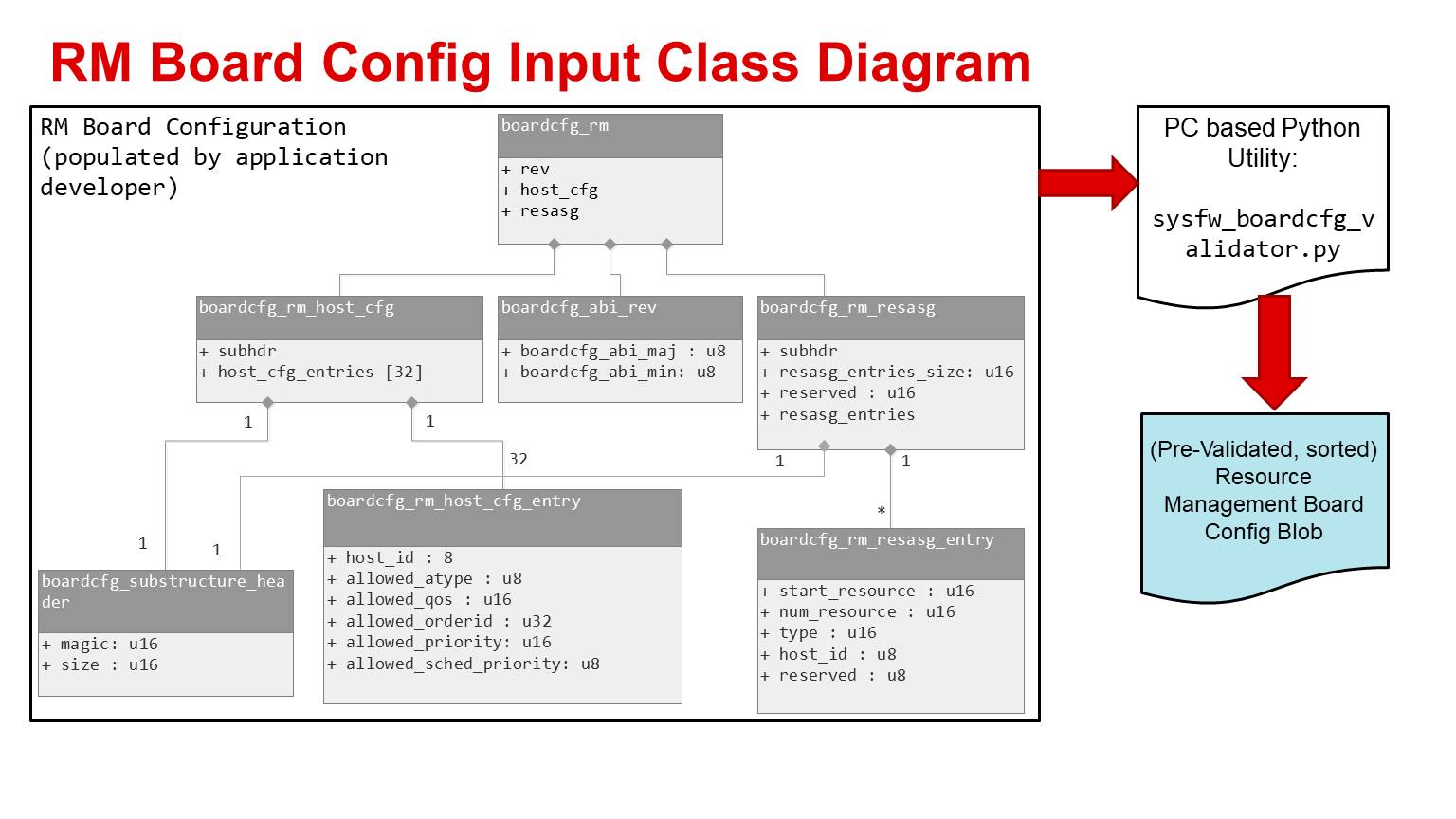
Details on how to use the sysfw_boardcfg_validator.py can be found by using the “–help” option to the script. The details on how to use this script is as shown below:
usage: sysfw_boardcfg_validator.py [-h] -b BINARY_FILE -s
                                        {am65x_sr2,j721e,am6}
                                        (-l LOG_OUTPUT_FILE | -L)
                                        [-o OUTPUT_BINARY_FILE] [-r RULES_FILE]
                                        [-i]

System Firmware Board Configuration Validator URL: http://software-
dl.ti.com/tisci/esd/latest/3_boardcfg/BOARDCFG.html

Required arguments - Define the inputs:
  -b BINARY_FILE, --binary_file BINARY_FILE
                        Binary File provided as input (default: None)
  -s {am65x_sr2,j721e,am6}, --soc {am65x_sr2,j721e,am6}
                        SoC supported by input binary (default: None)

Required arguments - Choose one of the outputs:
  -l LOG_OUTPUT_FILE, --log_output_file LOG_OUTPUT_FILE
                        Validation log output file (default: None)
  -L, --log_output_console
                        Report results to console (default: False)

optional arguments:
  -h, --help            show this help message and exit
  -o OUTPUT_BINARY_FILE, --output_binary_file OUTPUT_BINARY_FILE
                        Binary output file. Inline edit options of the binary
                        board configuration data are output to this file
                        (default: None)
  -r RULES_FILE, --rules_file RULES_FILE
                        Alternate Board configuration rules file (default:
                        /home/piyali/WORK/PROJECTS/SYSFW/system-firmware-
                        tools/system-firmware-
                        releases/binaries/scripts/sysfw_boardcfg_rules.json)
  -i, --inline_sort     Perform an inline sort of the Resource Management
                        board configuration resource assignments. The -o
                        option must be specified to output result of sort
                        (default: False)
Resource Assignment Validation
The resource assignment data is validated by the sysfw_boardcfg_validator.py script. The resource data is validated to prevent RM resource assignment errors that can cause operational failures during post-initialization runtime of the SoC applications. Validation criteria are:
- The resource assignment substructure header magic number must match the magic number defined for the RM boardcfg resource assignment substructure
- The resource assignment substructure header size must match the size of boardcfg_rm_resasg substructure definition.
- The resource assignment entry array size in bytes cannot be zero. The RM subsystem requires a resource assignment array in order to operate. Passing no resource assignments causes the RM boardcfg message to be rejected.
- The resource assignment entry array size cannot be greater than the size of the DMSC internal storage for the resource assignment array.
- The resource assignment entry array size must be a multiple of the boardcfg_rm_resasg_entry size
- Resource assignments can overlap to assign resources to multiple hosts
according to Static Resource Assignment Configurations.
The overlap validation criteria:
- No more than two resource ranges of the same resource type can overlap
- Overlapping resource ranges of the same resource type cannot be assigned to the same Host ID
- Resource ranges assigned to the HOST_ID_ALL Host ID cannot overlap with any other resource ranges of the same resource type
- Resource assignment ranges and types are checked by the RM subsystem drivers to make sure they are valid according to the SoC resources managed by each driver. The RM boardcfg message is rejected if a resource range is found to not have a valid type or resource range for the SoC managed resources.
- Resource assignment ranges and types are checked by the RM subsystem drivers to verify the ranges is not assignment usage of a DMSC reserved resource to a SoC Host ID. The RM boardcfg message is rejected if a resource range assigns a DMSC reserved resource to a Host ID. Any resource defined as “Reserved for use by DMSC” in the SoC Family Specific Documentation section of the user guide cannot be part of a resource assignment entry.
TISCI API for Resource Management Board Config
The following are the parameters required in the TI-SCI message to pass RM resource management board configuration data to DMSC after DMSC sends boot notification complete. The resource management board configuration message is not dependent on reception of the standard board configuration message.
Usage
| Message Type | Normal |
| Secure Queue Only? | No |
TISCI Message ID
TISCI_MSG_BOARD_CONFIG_RM (0x000CU)
Message Data Structures
struct tisci_msg_board_config_rm_req
TISCI_MSG_BOARD_CONFIG_RM request to provide the location and size of the boardcfg Resource Management configuration structure.
| Parameter | Type | Description |
|---|---|---|
| hdr | struct tisci_header | TISCI header |
| boardcfg_rmp_low | u32 | Low 32-bits of physical pointer to boardcfg RM configuration struct. |
| boardcfg_rmp_high | u32 | High 32-bits of physical pointer to boardcfg RM configuration struct. |
| boardcfg_rm_size | u16 | Size of RM configuration data. |
| boardcfg_rm_devgrp | devgrp_t | Device group for the RM configuration. |
struct tisci_msg_board_config_rm_resp
Empty response for TISCI_MSG_BOARD_CONFIG_RM.
| Parameter | Type | Description |
|---|---|---|
| hdr | struct tisci_header | TISCI header. |
Although this message is essentially empty and contains only a header a full data structure is created for consistency in implementation.
TI-SCI API for Get Resource Assignment Range
The following are the parameters required in the TI-SCI message to retrieve the range of a specific resource assigned to a host.
Usage
| Message Type | Normal |
| Secure Queue Only? | No |
TISCI Message ID
TISCI_MSG_RM_GET_RESOURCE_RANGE (0x1500U)
RM TISCI message to request a resource range assignment for a host
Message Data Structures
struct tisci_msg_rm_get_resource_range_req
Retrieves a host’s assigned range for a resource
| Parameter | Type | Description |
|---|---|---|
| hdr | struct tisci_header | Standard TISCI header |
| type | u16 | Resource assignment type used to form unique resource type. Only 10 LSB are valid. Types are found in the “Enumeration of Resource Type IDs” section of the DMSC public document. |
| subtype | u8 | Resource assignment subtype used to form unique resource type. Only 6 LSB are valid. Subtypes are found in the “Enumeration of Resource Type IDs” section of the DMSC public document. |
| secondary_host | u8 | The host processing entity attempting to allocate the ring if not set to @ref TISCI_MSG_VALUE_RM_UNUSED_SECONDARY_HOST. Otherwise, the host within the TISCI message header is the host attempting to allocate the ring. |
Returns the range for a unique resource type assigned to the specified host, or secondary host. The unique resource type is formed by combining the 10 LSB of type and the 6 LSB of subtype. Unique types which do not map to an SoC resource will not be NACK’d. Instead the tisci_msg_rm_get_resource_range_resp range_start and range_num values are both zeroed. This provides a known response mechanism across varied SoCs. Populating secondary_host with @ref TISCI_MSG_VALUE_RM_UNUSED_SECONDARY_HOST specifies the value as unused.
struct tisci_msg_rm_get_resource_range_resp
Get resource range response message
| Parameter | Type | Description |
|---|---|---|
| hdr | struct tisci_header | Standard TISCI header |
| range_start | u16 | Start index of retrieved resource range. |
| range_num | u16 | Number of resources in the range. Zero if the resource is not valid. |
| range_start_sec | u16 | Start index of retrieved secondary resource range. Zero if a second resource range does not exist or if the resource is not valid. |
| range_num_sec | u16 | Number of resources in secondary range. Zero if a second resource range does not exist or if the resource is not valid. |
Response sent to host processor containing the requested resource range assigned to the host who sent the range request. The range_start and range_num values are BOTH zero if the type and subtype in the range request do not form a unique resource type for the SoC. In this case, the response will still contain an ACK.
Warning
The boardcfg data structures described below must be placed in MCU OCMC SRAM. The address used in the TISCI message will be in MCU OCMC SRAM.
boardcfg_rm structure
| Field | Type | Description |
|---|---|---|
| rev | ABI revision structure | Resource Management board config ABI version (separate from primary board config ABI version) |
| host_cfg | boardcfg_rm_host_cfg structure | Host configuration structure |
| resasg | boardcfg_rm_resasg structure | Resource assignment configuration structure |
boardcfg_rm_host_cfg structure
| Field | Type | Description |
|---|---|---|
| subhdr | boardcfg substructure header | Magic and size for integrity check |
| host_cfg_entries | boardcfg_rm_host_cfg_entry structure [32] | Array sized for scalable number of hosts describing each host’s configuration attributes |
boardcfg_rm_host_cfg_entry structure
The boardcfg_rm_host_cfg_entry structure describes a host’s configuration attributes
| Field | Type | Description |
|---|---|---|
| host_id | u8 | Processing entity host ID |
| allowed_atype | u8 | Allowed atype configuration for the host ID. The host ID gets assigned a list of atypes which are allowed. atype is a 2-bit field with 3 possible values. Thus in one 8-bit word, flags are set specifying whether or not an atype value is allowed for the host ID. For each atype, the value of 01b means not allowed, 10b means allowed, and 11b and 00b are invalid/errors. These are encoded in a bitfield because there is one set of allowed atypes for every host ID. |
| allowed_qos | u16 | Allowed QoS level configuration for host ID. The host ID gets assigned a list of QoS levels which are allowed. As QoS level is a 3-bit field, there are 8 possible order-IDs. Thus in one 16-bit word, flags are set specifying whether or not the QoS level is allowed for the host ID. For each QoS level, the value of 01b means not allowed, 10b means allowed, and 11b and 00b are invalid/errors. These are encoded in a bitfield because there is one set of allowed QoS levels for every host ID. |
| allowed_orderid | u32 | Allowed order-ID configuration for the host ID. The host ID gets assigned a list of order-IDs which are allowed. As order-ID is a 4-bit field, there are 16 possible order-IDs. Thus in one 32-bit word, flags are set specifying whether or not the order-ID is allowed for the host ID. For each order-ID, the value of 01b means not allowed, 10b means allowed, and 11b and 00b are invalid/errors. These are encoded in a bitfield because there is one set of allowed order-IDs for every host ID. |
| allowed_priority | u16 | Allowed bus priority configuration for host ID. The host ID gets assigned a list of bus priorities which are allowed. As bus priority is a 3-bit field, there are 8 possible bus priorities. Thus in one 16-bit word, flags are set specifying whether or not the bus priority is allowed for the host ID. For each bus priority, the value of 01b means not allowed, 10b means allowed, and 11b and 00b are invalid/errors. These are encoded in a bitfield because there is one set of allowed bus priorities for every host ID. |
| allowed_sched_priority | u8 | Allowed UDMAP channel scheduling priority configuration for host ID. The host ID gets assigned a list of UDMAP channel scheduling priorities which are allowed. As UDMAP channel scheduling priority is a 2-bit field, there are 4 possible UDMAP channel scheduling priorities. Thus in one 8-bit word, flags are set specifying whether or not UDMAP channel scheduling priority is allowed for the host ID. For each priority, the value of 01b means not allowed, 10b means allowed, and 11b and 00b are invalid/errors. These are encoded in a bitfield because there is one set of allowed UDMAP channel scheduling priorities for every host ID. |
boardcfg_rm_resasg structure
| Field | Type | Description |
|---|---|---|
| subhdr | boardcfg substructure header | Magic and size for integrity check |
| resasg_entries_size | u16 | Size of resource assignment entry array in bytes |
| reserved | u16 | Reserved to keep 4-byte alignment |
| resasg_entries | boardcfg_rm_resasg_entry (resource assignment) structure [] | Array of resource assignment entries defined as variable length array. The user must define their own structure with a fixed length array in place of resasg_entries[]. |
Example user structure for RM boardcfg:
#define RESASG_ENTRIES (100)

struct local_rm_boardcfg {
    struct boardcfg_rm        rm_boardcfg;
    struct boardcfg_rm_resasg_entry    resasg_entries[RESASG_ENTRIES];
};
boardcfg_rm_resasg_entry (resource assignment) structure
There is one boardcfg_rm_resasg_entry per resource per host. This structure allows one contiguous block of any resource to be assigned to one processing entity
| Field | Type | Description |
|---|---|---|
| start_resource | u16 | First resource number (inclusive) for this host_id and resource type |
| num_resource | u16 | Number of continuous resources allocated to this host_id and resource type. 0 means unused |
| type | u16 | Unique type value identifying the resource whose range is assigned to host_id |
| host_id | u8 | Host ID as defined in secure proxy configuration |
| reserved | u8 | Byte reservation to assure contiguous resasg entries are aligned on 8-byte boundaries |
Design details for interrupt management
Within interrupt management, interrupts are routed through interrupt aggregators (IAs) and interrupt routers (IRs).
Whenever interrupt routers broadcast the interrupt to multiple interrupt controllers then it is possible for one processing entity to take outputs that could have been used by another processing entity, precluding the second processing entity from routing a required interrupt. Thus IRs with broadcast outputs need resource reservation capability. On AM6, these are the GPIO interrupt routers (in main and mcu), as well as the MAIN2MCU interrupt router.
Each interrupt aggregator virtual interrupt allows grouping up to 64 peripheral events to one host interrupt. It’s possible for one host to take all of these virtual interrupts. It’s also possible for one host to take all peripheral events. Thus, resource reservation capability is required for peripheral events and interrupt aggregator virtual interrupts.
Interrupt routes terminate at host processor interrupt controller inputs. A single host is capable of consuming all interrupt controller intputs. Therefore, resource reservation is required for host processor interrupt controller IRQs.
The unique types used to identify interrupt management reserved resources are found in Enumeration of Resource Type IDs.
Resource Management Initialization after receiving board configuration
Once the RM board configuration message is received by the System Firmware, it performs the following operations:
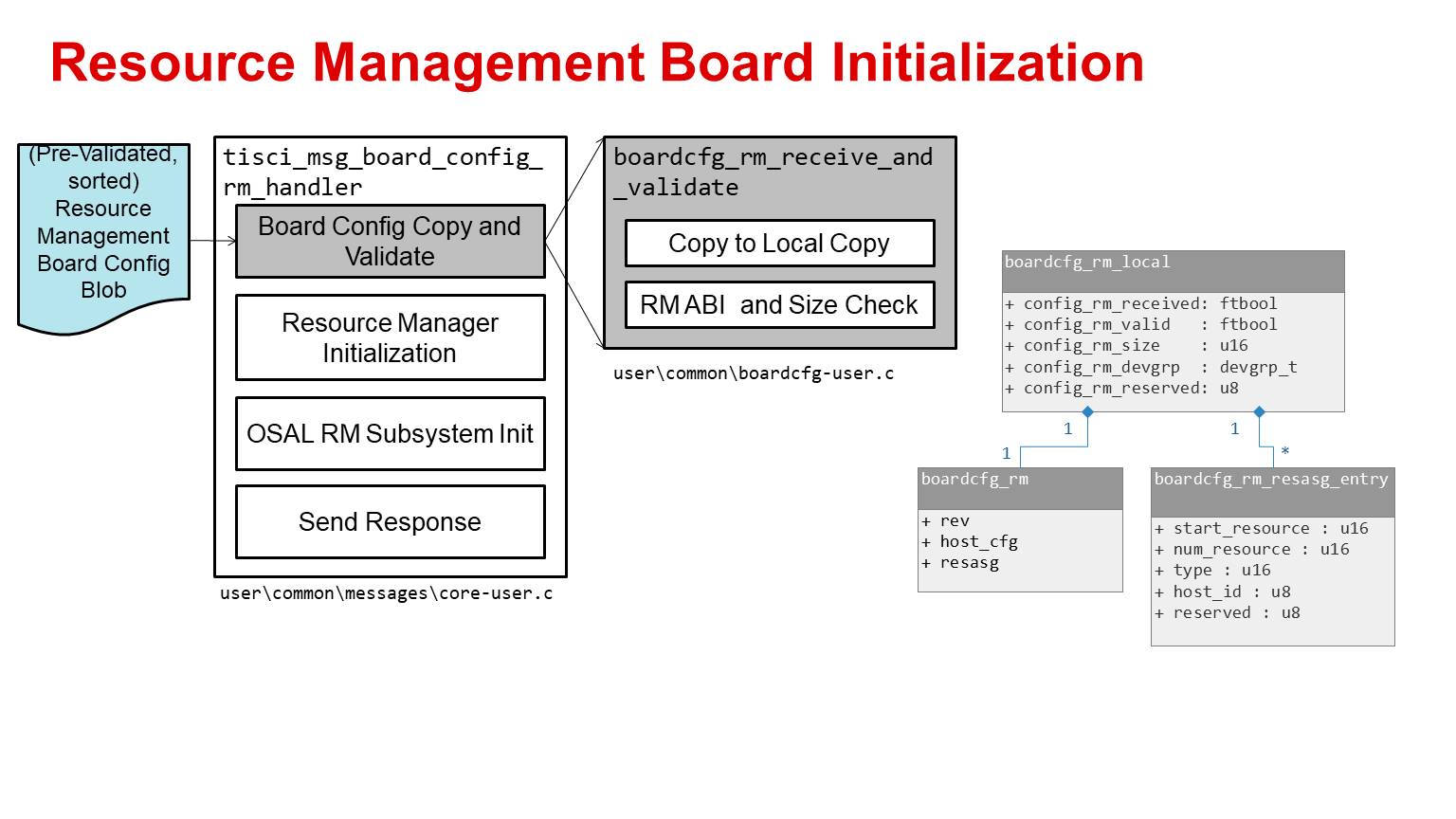
Board Configuration Receive and Validate
The first step after receiving the board configuration by the tisci_msg_board_config_rm_handler is to copy the board configuration into the local memory of the DMSC. The input is validated for ABI check and size checks.
Warning
The board configuration is assumed to be pre-sorted and validated using the script sysfw_boardcfg_validator.py. If the data is not pre-sorted the behavior of the RM functionality is undefined.
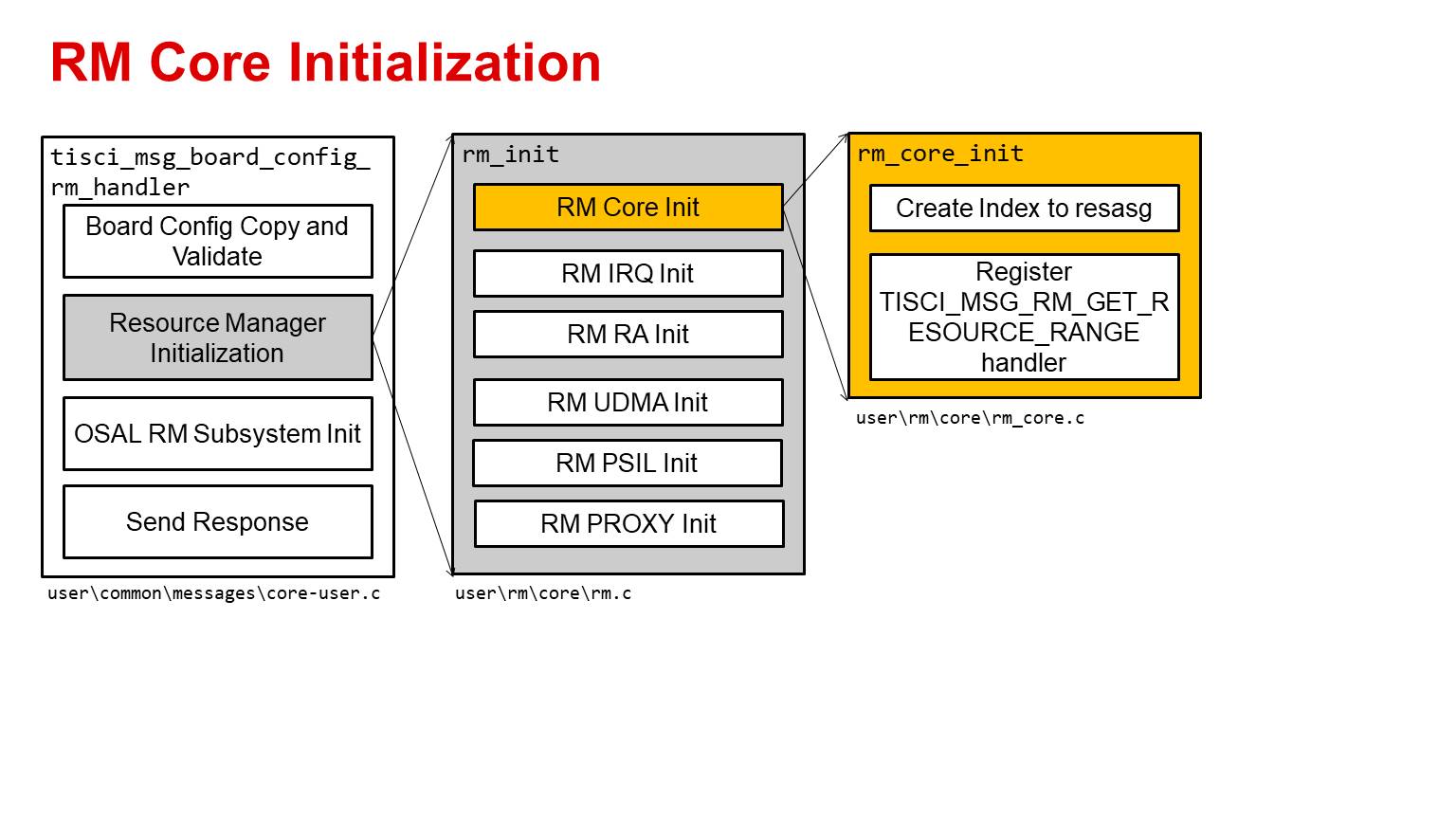
RM Core Initialization
The next step of the tisci_msg_board_config_rm_handler is to perform the RM Core initialization. This involves initialization of software structures to create an index to the resource assignment local copy for faster run time access. In addition the code also registers the software handler for the TISCI_MSG_RM_GET_RESOURCE_RANGE message.
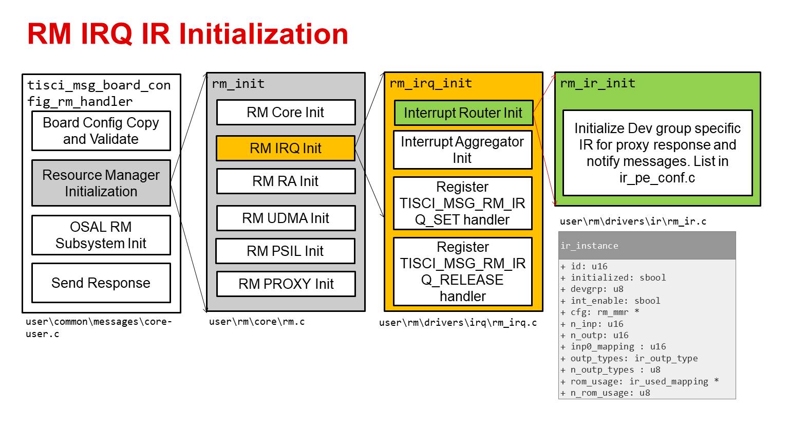
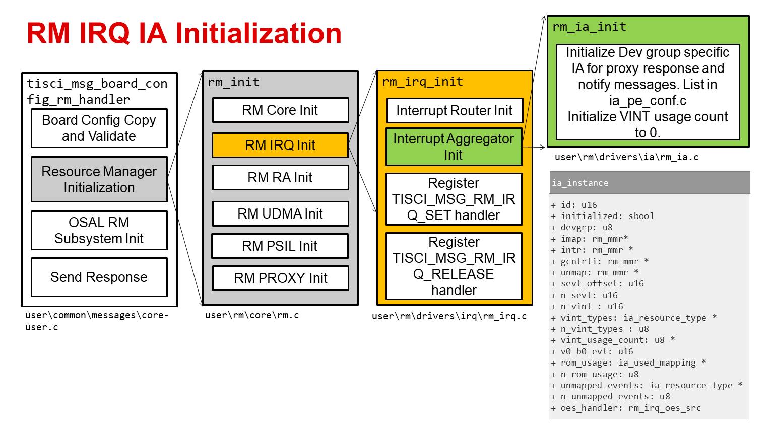
RM IRQ Initialization
The next step of the tisci_msg_board_config_rm_handler is to perform the RM IRQ initialization. As part of this step the code initializes the Dev group specific IR and IA for proxy response and notify messages. List of what is to be initialized is SoC specific and based on the secure proxy configuration.
In addition the code also registers the software handler for the
- TISCI_MSG_RM_IRQ_SET message
- TISCI_MSG_RM_IRQ_RELEASE message.
It also initializes software state information capture in the internal structures of ir_instance. This is a SoC specific System Firmware internal structure which is used to manage the Interrupt Router resource.
The IR initialization sequence is as below:
The IA initialization sequence is as below:
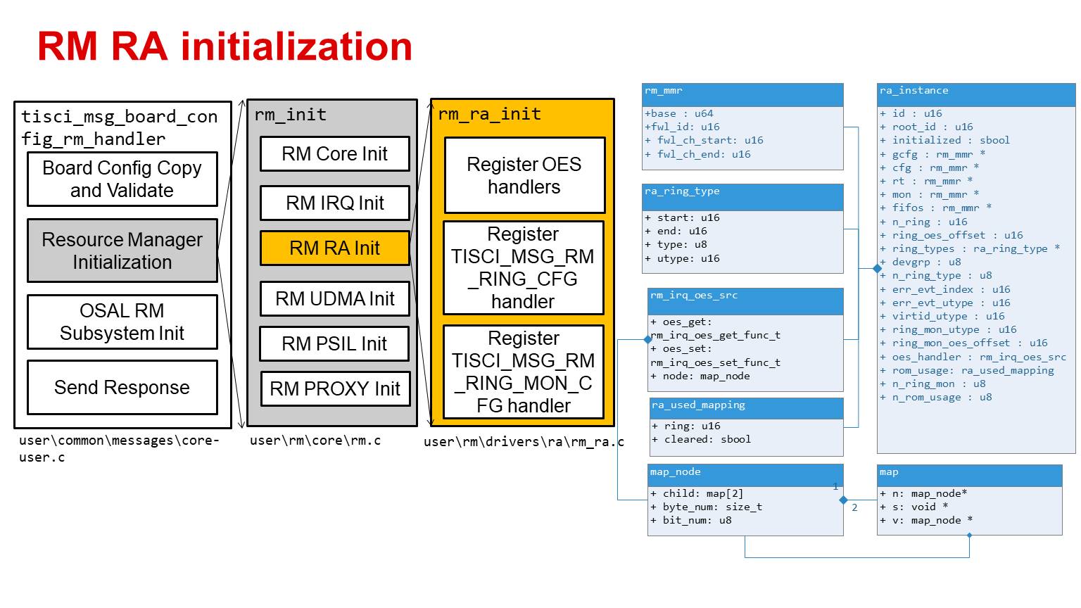
RM Ring Accelerator initialization
The next step of the tisci_msg_board_config_rm_handler is to perform the RM Ring Accelerator initialization. As part of this step the code initializes the Output Event Steering software handlers.
In addition the code also registers the software handler for the
- TISCI_MSG_RM_RING_CFG message
- TISCI_MSG_RM_RING_MON_CFG message
It also initializes software state information capture in the internal structures of ra_instance. This is a SoC specific System Firmware internal structure which is used to manage the ring accelerator resource.
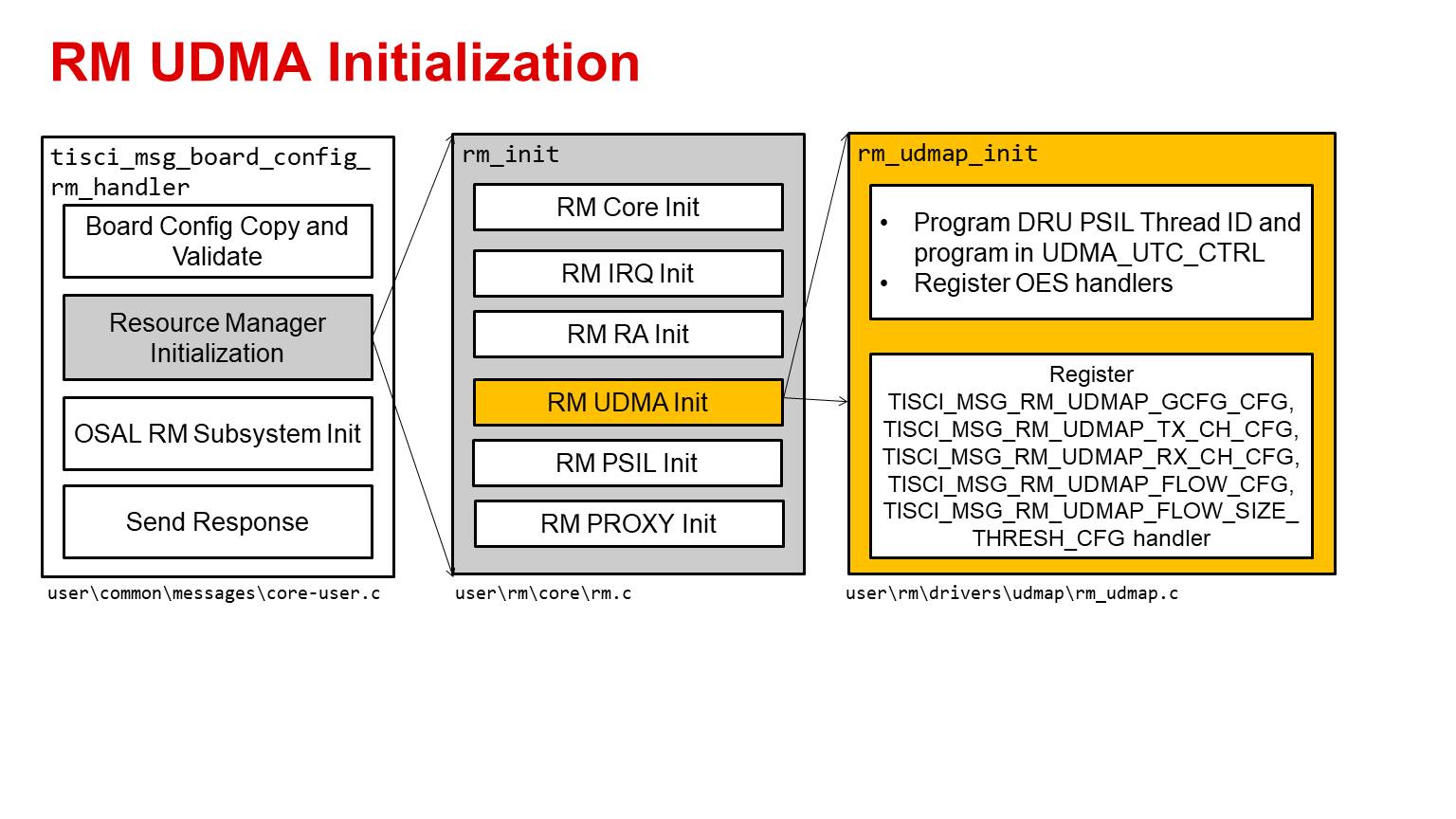
RM DMA Initialization
The next step of the tisci_msg_board_config_rm_handler is to perform the RM DMA initialization. As part of this step the code initializes the Output Event Steering software handlers. At this point the code also programs the DRU PSIL Thread ID and program in UDMA_UTC_CTRL for SoCs which support DRU.
In addition the code also registers the software handler for the
- TISCI_MSG_RM_UDMAP_GCFG_CFG message
- TISCI_MSG_RM_UDMAP_TX_CH_CFG message
- TISCI_MSG_RM_UDMAP_RX_CH_CFG message
- TISCI_MSG_RM_UDMAP_FLOW_CFG message
- TISCI_MSG_RM_UDMAP_FLOW_SIZE_THRESH_CFG message
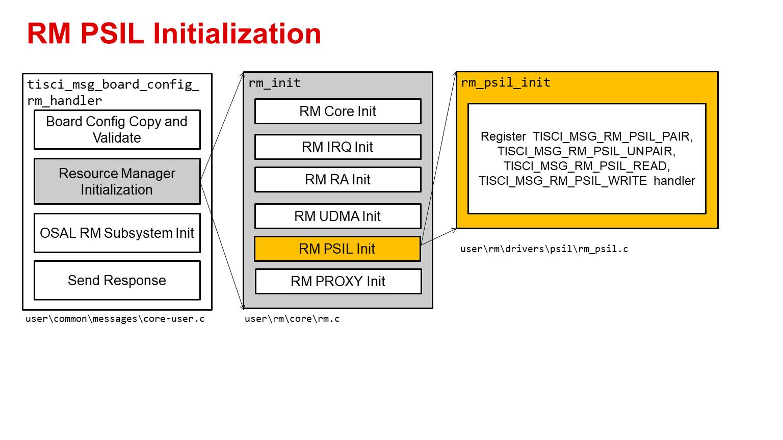
RM PSIL Initialization
The next step of the tisci_msg_board_config_rm_handler is to perform the RM PSIL initialization. At this step the code registers the software handler for the
- TISCI_MSG_RM_PSIL_PAIR message
- TISCI_MSG_RM_PSIL_UNPAIR message
- TISCI_MSG_RM_PSIL_READ message
- TISCI_MSG_RM_PSIL_WRITE message
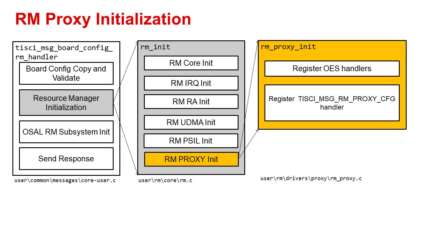
RM Proxy Initialization
The next step of the tisci_msg_board_config_rm_handler is to perform the RM Proxy initialization. As part of this step the code initializes the Output Event Steering software handlers.
In addition the code also registers the software handler for the
- TISCI_MSG_RM_PROXY_CFG message
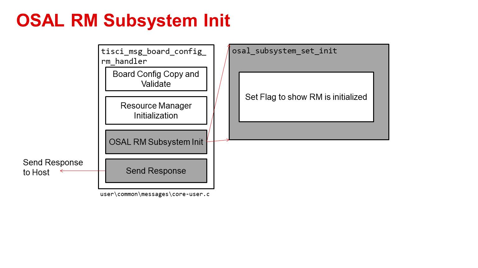
OSAL RM Subsystem Init
This is the last step in tisci_msg_board_config_rm_handler where the software state is updated to reflect the resource management is initialized and now can accept resource management messages.
After this step the host response is sent. If for any reason any of the above steps fail the API would return with a NACK.