Flash Layout for On-Chip OAD
This section will describe the method for placing placing images in internal flash when using on-chip OAD.
Constraints and Requirements for On-chip OAD (split image)
In order to perform an On-chip OAD the target system must have:
- The user application must be sufficiently small in order to fit into the flash layout system described below.
- User app functionality is lost while performing OAD. (Persistent app is running)
- Stack updates must be maintenance only, cannot change APIs
- Stack updates are done in two phases and must erase the user app first
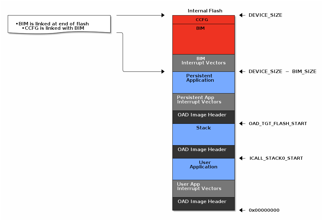
Internal Flash Memory Layout
The internal flash of the device contains the active user application, the stack, the persistent application, and the BIM. Each application’s role is defined below
| Application Name | Description |
| BIM |
|
| Persistent application |
|
| Stack |
|
| User app |
|
Note
When using security the BIM may use a second page depending on the page size of the device. Consult the BIM’s linker file for more information.
The user application pictured above is responsible for the following:
- Implementing the protocol stack definition of the OAD reset service
- Implementing customer defined behavior
The user persistent pictured above is responsible for the following:
- Implementing the protocol stack definition of the OAD service
- This image is permanently resident on the device