Architecture
The TI royalty-free Bluetooth low energy software development kit (SDK) is a complete software platform for developing single-mode Bluetooth low energy applications. This kit is based on the SimpleLink CC2640R2F, complete System-on-Chip (SoC) Bluetooth low energy solution. The CC2640R2F combines a 2.4-GHz RF transceiver, 128-KB in-system programmable memory, 20KB of SRAM, and a full range of peripherals. The device is centered on an ARM® Cortex®-M3 series processor that handles the application layer and Bluetooth low energy protocol stack and an autonomous radio core centered on an ARM Cortex®-M0 processor that handles all the low-level radio control and processing associated with the physical layer and parts of the link layer. The sensor controller block provides additional flexibility by allowing autonomous data acquisition and control independent of the Cortex-M3 processor, further extending the low-power capabilities of the CC2640R2F. Figure 3. shows the block diagram. For more information on the CC2640R2F, see the CC26xx Technical Reference Manual.
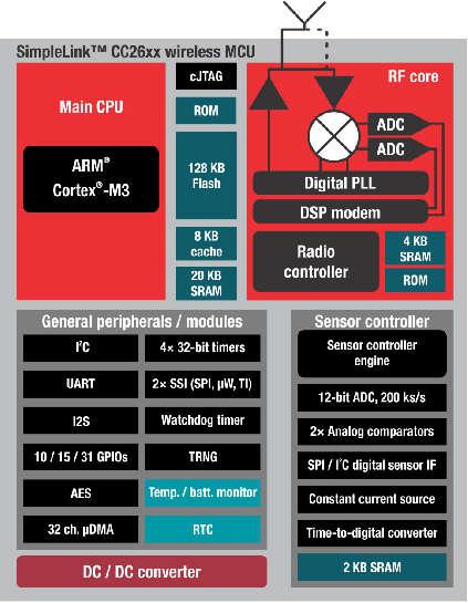
Figure 3. SimpleLink CC2640R2F Block Diagram
Hardware and Software Architecture
This section aims to introduce the different cores within the CC2640R2F, how they interact, and the firmware that runs on them. The information presented here should be considered as an overview. For detailed descriptions of the hardware described here, refer to the chapter 23 of the CC26xx Technical Reference Manual.
ARM Cortex M0 (Radio Core)
The Cortex M0 (CM0) core within the CC2640R2F is responsible for both interfacing to the radio hardware, and translating complex instructions from the Cortex M3 (CM3) core into bits that are sent over the air using the radio. For the Bluetooth low energy protocol, the CM0 implements the PHY layer of the protocol stack. Often, the CM0 is able to operate autonomously, which frees up the CM3 for higher-level protocol and application-layer processing.
The CM3 communicates with the CM0 through a hardware interface called the RF doorbell, which is documented in section 23.2 of the CC26xx Technical Reference Manual. The radio core firmware is not intended to be used or modified by the application developer.
ARM Cortex M3 (System Core)
The system core (CM3) is designed to run the Bluetooth low energy protocol stack from the link layer up to the user application. The link layer interfaces to the radio core through a software module called the RF driver, which sits above the RF doorbell. The RF driver runs on the CM3 and acts as an interface to the radio on the CC2640R2F, and also manages the power domains of the radio hardware and core. Documentation for the RF driver can be found at the TI-RTOS Drivers Reference. Above the RF driver is the TI Bluetooth low energy protocol stack, which is implemented in library code.
The application developer interfaces with the protocol stack through a set of APIs (ICall) to implement a Bluetooth low energy application. The rest of this document intends to document application development on the CC2640R2F using the Bluetooth low energy stack.
BLE5-Stack Protocol Stack and Application Configurations
Figure 4. shows the platform that supports two different protocol stack and application configurations.
- Single device: The controller, host, profiles, and application are all implemented on the CC2640R2F as a true single-chip solution. This configuration is the simplest and most common when using the CC2640R2F. This configuration is used by most of TI’s sample projects. This configuration is the most cost-effective technique and provides the lowest-power performance.
- Simple network processor: The Simple Network Processor (SNP) implements the controller and host layers of the BLE5-Stack. Additionally, the SNP exposes an interface for scheduling communication between the stack and an external MCU. This accelerates dual MCU designs because the application processor (AP) is only responsible for managing custom profiles and application code. Stack-related functionality, such as security, is implemented on the SNP. The SNP currently supports the peripheral and broadcaster GAP roles. Communication with the SNP is carried out through the SNP API. The SNP API is built on the Unified Network Processor Interface (UNPI), which supports UART and SPI transport layers. For more information, reference the Unified Network Processor Interface wiki page. TI also provides the SAP library, which implements a UNPI master and the SNP API. The SAP library can be ported to any TI-RTOS-capable processor, or used as a reference for developing a custom dual MCU solution. For a description of the SNP, see the README.html page within the simple_np folder, advanced users can read the SNP API Reference for a summary of the supported commands.

Figure 4. Single-Device Processor and Simple Network Processor Configurations
Solution Platform
This section describes the various components that are installed with BLE5-Stack 1.00.01.04 and the directory structure of the protocol stack and any tools required for development. Figure 5. shows the BLE5-Stack development system.
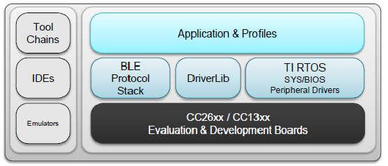
Figure 5. Bluetooth low energy Stack Development System
The solution platform includes the following components:
- TI’s Real-Time Operating System (TI-RTOS) with the TI-RTOS kernel, optimized power management support, and peripheral drivers (SPI, UART, and so forth)
- CC26xxware DriverLib provides a register abstraction layer and is used by software and drivers to control the CC2640R2F SoC.
- The Bluetooth low energy protocol stack is provided in library form with parts of the protocol stack in the CC2640R2F ROM.
- Sample applications and profiles make starting development using both proprietary and generic solutions easier.
The following integrated development environments (IDEs) are supported:
- IAR Embedded Workbench for ARM
- Code Composer Studio™ (CCS)
Refer to the SDK release notes for the specific IDE versions supported by this release.
BLE Software Architecture
The CC2640R2F Bluetooth low energy software environment consists of the following parts:
- An application image with the TI-RTOS kernel, drivers and Bluetooth profile
- A stack image or library that implements Bluetooth low energy protocol
TI-RTOS is a real-time, pre-emptive, multithreaded operating system that runs the software solution with task synchronization. Both the application and Bluetooth low energy protocol stack exist as separate tasks within the RTOS. The Bluetooth low energy protocol stack has the highest priority. A messaging framework called indirect call (ICall) is used for thread-safe synchronization between the application and stack. Figure 6. shows the architecture.
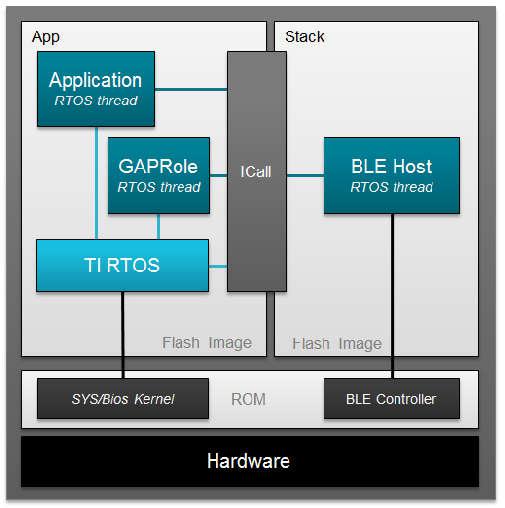
Figure 6. Example Software Architecture
- The stack image includes the lower layers of the Bluetooth low energy protocol stack from the LL up to and including the GAP and GATT layers. Most of the Bluetooth low energy protocol stack code is provided as a library.
- The application image includes the RTOS, profiles, application code, drivers, and the ICall module.
Protocol Stack Build Configurations
The BLE5-Stack applications have different options for configuring the protocol stack to maximize system implementations. These options are described below along with the relevant advantages and limitations.
Note
This section aims to explain the two supported protocol stack build configurations. Additionally, the protocol stack itself may be configured to conditionally pull in different library builds based on the features needed. Configuring the protocol stack is covered in Stack Configurations
Stack Library Configuration (_stack_library)
In BLE5-Stack 1.00.01.04, stack can be built as a library that can be statically linked
to the application. Projects with build with this new configuration can be
identified by project build configurations with _stack_library in its
configuration name. Using this build configuration will yield additional flash
footprint optimizations by the linker since the application and stack can share
contiguous flash pages. The gained footprint savings will however prevent
split-image application. See
Available CCS project build configurations and
Available IAR project build configurations for the available project build
configurations. Stack library projects have the following properties
- Stack project generates a static library (.lib)
- Application project will now link the stack in as a library
- There is no explicit app/stack boundary. The application’s link step decides the memory locations of the code within the stack_library. There are some exceptions to this such as SNV.
- This architecture saves flash by allowing the linker work more efficiently.
- These projects used the improved ICall architecture
Split Image Configuration
As with previous BLE-Stack releases, application and stack images are built as two separate projects that generate two separate images. These images occupy separate, non-overlapping flash memory pages. The split image configuration is useful in purposes such as OAD where it could be advantageous to perform independent application or stack downloads. Split image projects have the following properties:
- Fixed stack entry point
- Stack project generates a separate executable (.hex, .out, .bin)
- Explicit Flash/RAM boundaries between app and stack
- Independent update of stack/app (API compatibility must be ensured by the user)
Project Build Configurations
Sample applications within the BLE5-Stack portion of the SimpleLink CC2640R2 SDK support multiple build configurations to enable using the protocol stack build types discussed above. Other build configurations may have been created to support features such as RCOSC or OAD out of the box. The table below gives a summary of the build configurations found within BLE5-Stack and their compatibility with one another.
| Project type | Project’s build configuration | Description |
| Application | FlashROM | Application image build configuration. Requires companion Stack FlashROM (split image configuration) |
| FlashROM_StackLibrary | Application build configuration linked to Stack library (fully executable) | |
| FlashROM_StackLibrary_RCOSC | Application build configuration linked to Stack library for 32-kHz crystal-less device configuration | |
| FlashROM_OAD_Offchip | OAD off-chip application FlashROM configuration | |
| Stack | FlashROM_Library | Stack library build configuration |
| FlashROM | Stack image using protocol stack in ROM configuration |
Note
Some of the build configurations above may be located in a separate
project for CCS, for example simple_peripheral_cc2640r2lp_app_oad_offchip.
However the principles of the table above can still be applied. Always
consult the README.html file of the specific sample application for
more information on it’s supported build configurations. Additionally,
refer to Available CCS project build configurations
Converting Library Build to Split Image
All BLE5-Stack 1.00.01.04 projects will support the Library build configuration. Most Application and Stack projects will not have a split-image build configuration.
A split Application and Stack configuration is required for on-chip OAD applications where only the stack or the application image is planned to be upgraded. Library configuration only supports full application + stack image off-chip OAD.
Convert the Stack Project in an executable image (IAR)
- Select the Stack Project as Active Project
- It’s recommended to create a new project build configuration: Project –> Edit Configurations –> Select New and supply a new name for the build configuration.
- Open Project Properties
- Right Click on Project –> Options
- Go to General Options –> Output Tab
- Select Executable for “Output File”
Note
This will now enable debugger settings which will default to the simulator.
- Go to C/C++ Compiler Options –> Preprocessor Tab
- Remove the defined STACK_LIBRARY symbol from the “Defined symbols” list.
- Go to Build Actions
Add the Frontier boundary tool as a Post Build step:
"$TOOLS_BLE_DIR$/frontier/frontier.exe" iar "$PROJ_DIR$/$CONFIG_NAME$/List/$TARGET_BNAME$.map" "$PROJ_DIR$/../config/iar_boundary.bdef" "$PROJ_DIR$/../config/iar_boundary.xcl"
Note
This tool hands information to the Application regarding Stack Entry Point.
- Go to Linker Options –> Extra Options Tab
Select Use command line options
Add the following into the Command line options: (one per line) window:
-f $PROJ_DIR$/../config/lib_linker.cmd
- Go to Debugger Option
Reconfigure Debugger Settings based on the debugger that you using. TI’s development boards generally use the TI XDS110 Emulator debugger.
Update the Application Project to use the executable Stack Project image (IAR)
- Select the Application Project as Active Project
- It’s recommended to create a new project build configuration:
- Project –> Edit Configurations –> Select New and supply a new name for the build configuration.
- Exclude StackLibrary IDE folder from the build.
- Right-click on StackLibrary –> Options...
- Check Exclude from build and select OK
- Open Project Properties
- Right Click on Project –> Options
- Go to C/C++ Compiler Options –> Preprocessor Tab
- Remove the defined STACK_LIBRARY symbol from the “Defined symbols” list.
- Go to Linker Options –> Config Tab
Use the Linker configuration file this .icf linker file:
$SRC_BLE_DIR$/common/cc26xx/iar/cc26xx_app.icfRemove FLASH_ROM_BUILD=2 from Configuration file symbol definitions: (one per line)
- Go to Linker Options –> Library Tab
Remove the following from the Additional libraries: (one per line) window:
$PROJ_DIR$\..\config\ble_r2.symbolsAdd the following to the Additional libraries: (one per line) window:
$ROM_DIR$\ble_rom_releases\cc26xx_r2\Final_Release\common_r2.symbols
- Go to Linker Options –> Extra Options Tab
Remove the following from the Command line options: (one per line) window:
-f $PROJ_DIR$/../config/lib_linker.cmd
Standard Project Task Hierarchy
Considering the simple_peripheral project as an example, these tasks are listed by priority. A higher task number corresponds to a higher priority task:
- Priority 5: Bluetooth low energy protocol stack task (must be highest priority)
- Priority 3: GapRole task (peripheral role)
- Priority 1: Application task (simple_peripheral)
TI-RTOS Overview introduces TI-RTOS tasks. Overview describes interfacing with the Bluetooth low energy protocol stack. GAPRole Task describes the GapRole task. Pre-main initialization describes the application task.
Directory Structure
The default install location is: C:\ti\simplelink_cc2640r2_sdk_x_xx_xx_xx.
The SDK installs to this location by default. For the purposes of this document, consider the above path to the BLE5-Stack root directory; it will be omitted. All paths will be relative to the BLE5-Stack root directory. Opening up the root install directory shows the new parent folders within the SDK, as shown in Table 3.
| BLE5-Stack 1.00.01.04 folders | Purpose |
|---|---|
| docs\ | The docs directory now contains all relevant documents included with the CC2640R2F SDK. Refer to the Documentation Overview master page. |
| examples\ | The CC2640R2F SDK includes ble examples as well as TI-RTOS kernel and TI-RTOS driver examples. |
| kernel\ | The TI-RTOS kernel is now included with the CC2640R2F SDK. |
| source\ | The source\ directory include source for BLE5-Stack, TI-RTOS kernel and drivers, and various middleware modules. |
| tools\ | Tools such as BTool |
Examples Folder
The examples\ folder contains example source files for the BLE5-Stack, TI-RTOS kernel, and TI-RTOS drivers. All the source code supporting the SimpleLink CC2640R2 SDK examples can be found at *examples\rtos\CC2640R2_LAUNCHXL\. Examples for each product can be found within their respective folders and are accessible via various means as shown in Examples available for the CC2640R2F platform.
| Type of examples | Example subdirectory | How to open the examples |
|---|---|---|
| BLE5-Stack | ble5stack\ | Imported via TI Resource Explorer
Opened as existing IAR projects
|
| TI-RTOS Kernel | sysbios\ | |
| TI-RTOS Drivers | drivers\ |
For TI-RTOS Kernel and TI-RTOS driver examples, see the linked documentation. To help select a specific BLE example, see BLE examples available for the CC2640R2F platform. As with previous BLE-Stack releases, each example contains a toolchain subdirectory for CCS and IAR.
IAR examples are available as .eww projects whereas CCS project are imported.
See Table 1. for a list of examples supported by the SDK.
Source Folder
The source\ti\ folder contains libraries and source files for the BLE5-Stack, TI-RTOS drivers, and various shared modules. They can be found within their respective folders as shown in CC2640R2F SDK’s source\ti\ directory.
| source\ti\ | subdirectory | Purpose |
|---|---|---|
| ble5stack\ | Root source directory for the BLE5-Stack | |
| blelib\ | Prebuilt BLE stack libraries | |
| boards\ | Sample board files for use with the BLE stacks | |
| common\ | Linker, RTOS config, and middleware used by the stack | |
| config\ | Symbol files for various stack builds and configurations | |
| controller\ | Header files for the BLE controller layer | |
| hal\ | Hardware abstraction layer files for Stack | |
| heapmgr\ | Heap Manager | |
| host\ | Header files for the BLE host layers | |
| icall\ | Source files for the ICall module | |
| inc\ | Header files used to interface with BLE5-Stack | |
| microstack\ | Source files for the Micro BLE Stack | |
| npi\ | Source files for the both NPI modules | |
| osal\ | Source support files used by the BLE5-Stack | |
| profiles\ | Sample BLE profile implementations | |
| rom\ | BLE5-Stack ROM symbol files | |
| services\ | Miscellaneous support files | |
| symbols\ | ROM patch support files | |
| target\ | Board gateway folder | |
| devices\ | Support files from driverlib | |
| display\ | Display module | |
| drivers\ | TI-RTOS drivers source and libraries | |
| grlib\ | Graphics library | |
| mw\ | Other middleware modules dependent on TI-RTOS drivers | |
Working With Hex and Binary Files
BLE5-Stack projects have project build configurations in which the application and stack projects produce an Intel®-extended hex file in their respective output folders. These hex files lack overlapping memory regions and can be programmed individually with a flash programming tool, such as SmartRF Flash Programmer 2. . To simplify the flash programming process, you can combine the application and stack hex files into a super hex file manually or using freely available tools. Information on the Intel Hex standard.
One example for creating the super hex file is with the IntelHex python script hex_merge.py, available at IntelHex launchpad. To merge the hex files, install Python® 2.7.x and add it to your system path environment variables.
Warning
Note that when using any python script, you must use a compatible version of Python. Refer to the tool documentation or contact the developer to verify compatibility.
The following is an example usage to create a merged simple_peripheral_cc2640r2lp.hex file consisting of the individual application and stack hex files:
1 2 3 4 5 6 | C:\Python27\Scripts>python hexmerge.py \
-o .\simple_peripheral_cc2640r2lp_merged.hex \
-r 0000:1FFFF
simple_peripheral_cc2640r2lp_app.hex:0000:1FFFF
simple_peripheral_cc2640r2lp_stack.hex
--overlap=error
|
If conversion of the super hex to binary is desired, this can be accomplished with the “hex2bin.py” or similar tools that support the hex standard.
1 2 3 | C:\Python27\Scripts>python hex2bin.py \
simple_peripheral_cc2640r2lp_merged.hex \
simple_peripheral_cc2640r2lp_merged.bin
|
Programming Internal Flash with the ROM Bootloader
The CC2640R2F internal flash memory can be programmed using the bootloader in the ROM of the device. Both UART and SPI protocols are supported. For more details on the programming protocol and requirements, see the Bootloader chapter of the CC26xx Technical Reference Manual.
Note
Because the ROM bootloader uses predefined DIO pins for internal flash programming, allocate these pins in the layout of your board. For details on the pins allocated to the bootloader based on the chip package type, see CC26xx Technical Reference Manual.