Radio Configuration
You can use SysConfig to configure the radio settings. E.g. if you are
using an RF Driver project, you can use the Custom RF
Stack SysConfig view to add settings to ti_radio_config.c/h. It is also
possible to SmartRF Studio to configure the RF settings. In this case you
will get files named smartrf_settings.c/h, corresponding to the
ti_radio_config.c/h files generated by SysConfig.
Most configurable parameters in the Custom RF Stack view are also found as a configurable parameter in SmartRF Studio. If there is a specific parameter you need documentation about, please check SmartRF Studio or in the CC13x2 CC26x2 SimpleLink Wireless MCU Technical Reference Manual.
In the following sections, rfPacketTx is used as the example, but the
instructions are valid for any example project that uses
smartrf_settings.c/h to configure the RF settings.
Note
Custom RF Stack configuration in SysConfig will only make changes to
ti_radio_config.c/h. Any required changes to your application files
you must do on your own.
Open An Example Project
Open the standalone SysConfig tool or a SysConfig-enabled example project.
Open the .syscfg file.
Adding RF Settings
In the RF STACKS view, you can add sets of settings for multiple RF stacks. If
you’re not using one of the RF stacks, you can use the Custom option to add a
direct configuration of the Smartrf Settings (ti_radio_config.c/h).
Press the Plus sign next to Custom to add a configuration.
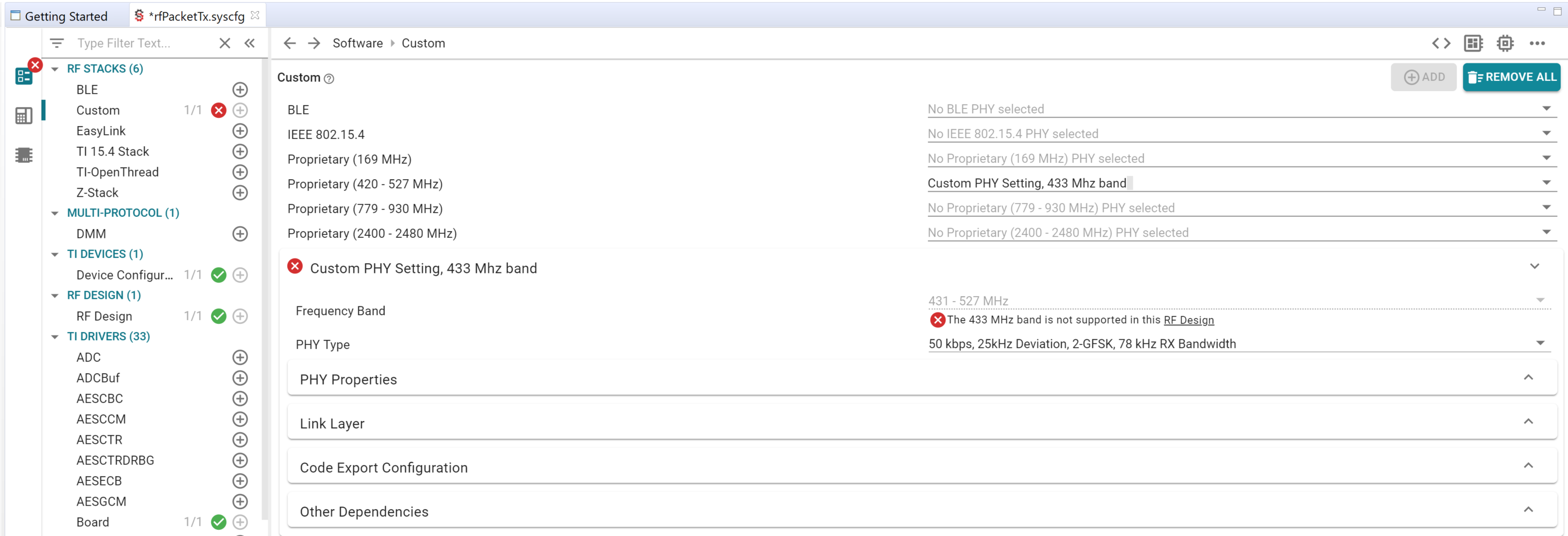
When you open the Custom RF Stack view you will see that the RF settings are divided into modes; Proprietary mode for the 431 - 527 MHz band, Proprietary mode for the 799 - 930 MHz band, BLE mode, IEEE 802.15.4 mode. You can have multiple sets of RF settings defined simultaneously.
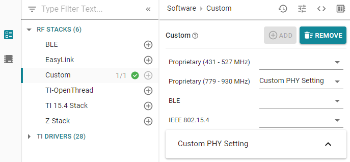
Add RF Mode
Add at least one set of RF Settings in the Custom RF Stacks view. For each mode, you will have to choose the PHY type. Each time an RF Settings mode is added, a box will appear in SysConfig that will allow you to configure the chosen PHY.
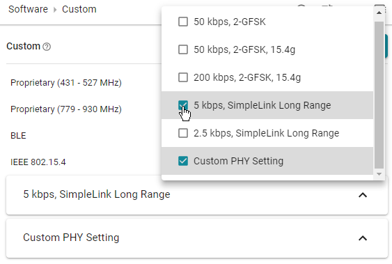
Choose PHY Type
You can choose a pre-configured PHY type, or choose Custom PHY Setting. Each time an RF Settings mode is added, a box will appear in SysConfig that will allow you to configure the chosen PHY. You can have one or more PHY settings for each RF mode.
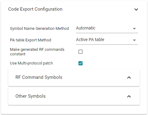
Name the Set of RF Settings
Each set of RF Settings must have a name, which is used when generating every RF driver command. Two different sets of RF Settings can not have the same name. Scroll down to Code Export Configuration and select the desired Symbol Name Generation Method:
Legacy - Bare-bones names are generated. You can only have one set of RF Settings with the Legacy name.
Automatic - Each object will be given the selected PHY as a suffix.
Custom - You can configure the name as you like.
You can see the generated names in the RF Command Symbols and Other Symbols tabs.
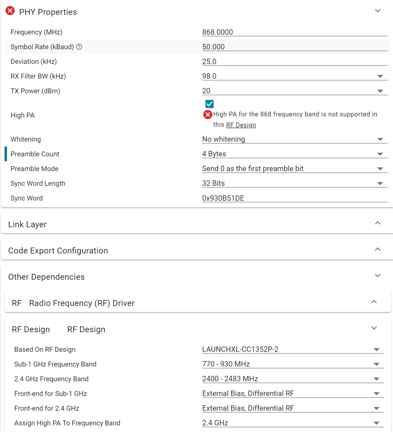
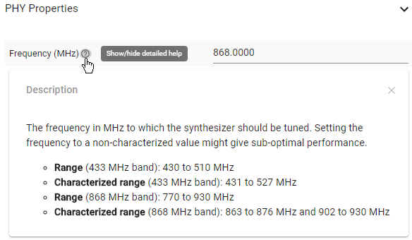
Set the PHY Properties
(For BLE and IEEE 802.15.4 settings you will not get this tab.) In the PHY Properties tab you can set basic properties such as frequency and Tx Power to use, and settings related to packet format such as the sync word.
Each parameter is more thoroughly explained if you press the small circle with a question mark next to the parameter name.
Make sure your settings make sense from an RF point of view. Certain parameter combinations will give you a build error. Other will give you a hint to a file where you need to change a different parameter based on your SysConfig parameters. In this case, make sure to comply (as SysConfig will not make this change for you).
Set the Link Layer Options
(For BLE and IEEE 802.15.4 settings you will not get this tab.) In the Link Layer tab you can set packet parameters such as packet length and Rx address to filter on.
The Other Dependencies Tab
In this tab you can configure options that are defined outside of the RF STACKS view in SysConfig. E.g. the RF Driver is found under the TI DRIVERS view. If you change the RF Driver settings here, you will see your changes reflected in the TI DRIVERS view.
Save the
.syscfgfile.Generate the files
You can see the generated files by clicking the
<>symbol. In this example,ti_drivers_config.c/hwas generated by the “TI Drivers” view andti_radio_config.c/hwas generated by the “RF Stacks” view. In addition,ti_devices_config.c(previously calledccfg.c) andsyscfg_c.rov.xsare generated.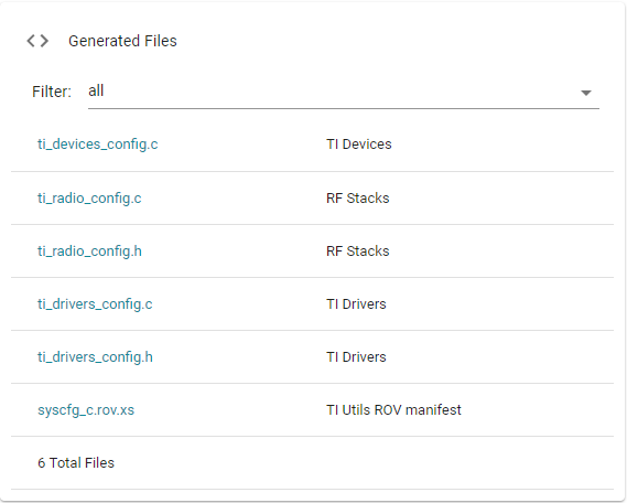
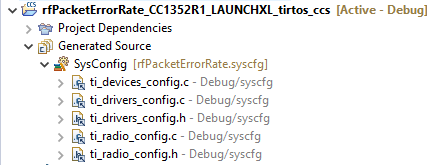
After the build has completed, you will find the generated files in the output folder of your project. In this example, it’s the folder called “Debug” of the rfPacketTx example.
The Radio Settings are shown separately in the generated
ti_radio_config.cfile. In this example, one set of RF Settings was added. These settings are found under aRF Settingheader.//********************************************************************************* // RF Setting: 50 kbps, 2-GFSK, 25 kHz deviation // // PHY: 2gfsk50kbps // Setting file: setting_tc106.json //*********************************************************************************
Adjust Your Application Files
The names of RF objects have been generated according to the naming rules chosen in Code Export Configuration. Make sure your application is using the correct name whenever an RF object is used.
In this example, RF objects are only called from
rfPacketTx.c. For each RF object, make sure the name is correct according to the RF Settings you have generated. This is also valid if your application uses multiple sets of RF Settings. Use build errors and warnings to make sure you are using the correct names.Attention
Whenever you re-build the project, SysConfig will re-generate the files. Because of this, any changes made directly in the files (
smartrf_settings.c/h) will be overwritten and lost.
Selecting an RF Design
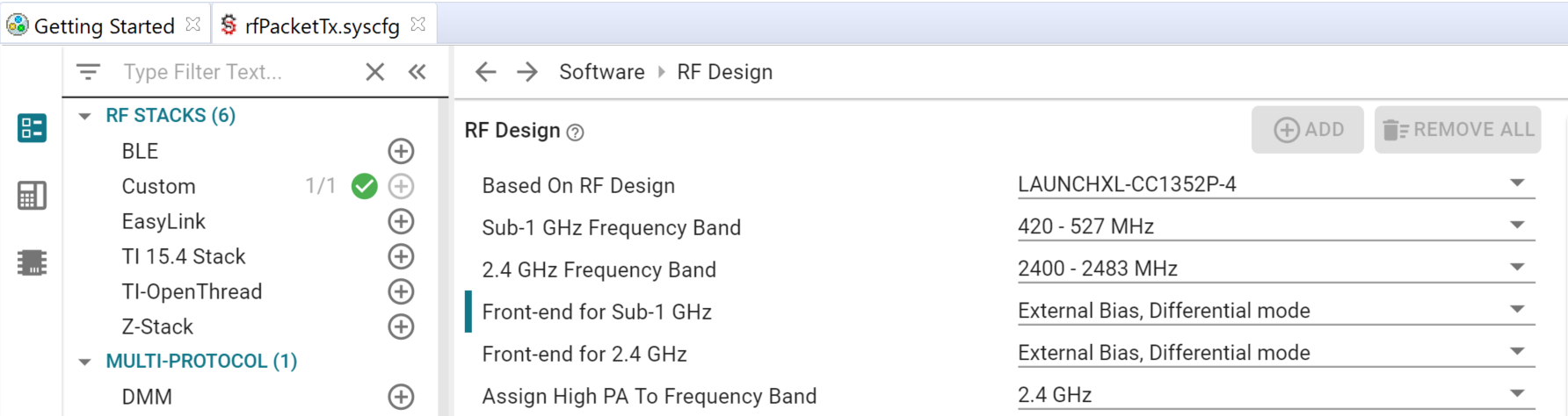
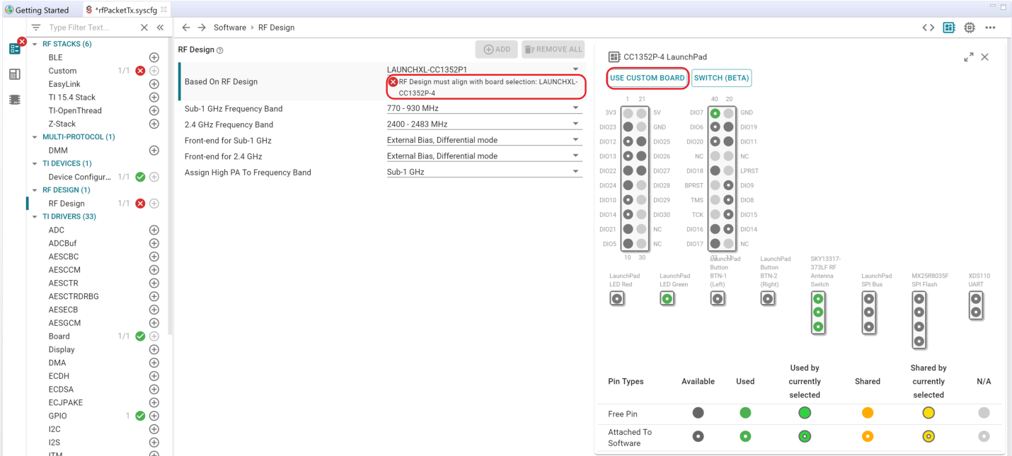
In the RF DESIGN view, you can select which radio features to include in your design, with respect to frequency band, RF front-end and the use of high output power PA (only available on the P devices). All designs are based on existing TI reference designs.
When using SysConfig through CCS the board is already locked in the IDE and to change the Based on RF Design you will need to select USE CUSTOM BOARD first.
Select RF Design
The existing RF designs are:
LAUNHXL-CC1352P1
LAUNHXL-CC1352P-2
LAUNHXL-CC1352P-4
LAUNHXL-CC1312R1
LAUNHXL-CC1352R1
LAUNHXL-CC26X2RB
LAUNHXL-CC26X2R1
CC1352EM-XS169-XS24, 10 dBm
LPSTK-CC1352R1
The available RF designs corresponds to the available RF designs in SmartRF Studio for the given device, i.e. you can choose between designs that uses the same front-end configuration.
Select Frequency Band
Here you will need to select Sub-1 GHz frequency band for the CC1312R device, 2.4 GHz frequency band for the CC26x2 devices, and both for the CC1352R and CC1352P devices. The different frequency bands are:
- Sub-1 GHz:
169 MHz
420 - 527 MHz
770 - 930 MHz
- 2.4 GHz:
2400 - 2483 MHz
Which frequency band to select, depends on the selected RF design. For example, if you have selected LAUNHXL-CC1352P-4, you will experience degraded performance if you select the 770 - 930 MHz band. Also, you will get an error under RF Stacks if there is a mismatch between your selected RF design and the frequency band you are using.
Select Front-End
Select front-end (and bias mode) for Sub-1 GHz, 2.4 GHz or both, depending on which RF design you have. The available options are:
External Bias, Differential mode
Internal Bias, Differential mode
External Bias, Single-Ended mode RFP
External Bias, Single-Ended mode RFN
You can choose between internal and external bias, single-ended or differential, and your selections is reflected in the RF_cmdPropRadioDivSetup.config.biasMode and RF_cmdPropRadioDivSetup.config.frontEndMode in
ti_radio_config.c.Assign High PA to Frequency Band
The high power PA can be assigned to the following frequency band:
None
Sub-1 GHz
2.4 GHz
3 different power amplifiers (PAs) are available for the SimpleLink CC13xx/CC26xx platform (5, 13, and 20 dBm), but only certain combinations of frequency bands and power amplifiers are possible. The high power PA is the only one that supports both the sub-1 GHz band and the 2.4 GHz band and that can be assigned to one one of the bands. The 5 dBm PA is 2.4 GHz only and the 13 dBm PA is sub-1 GHz only.
If you for example assigned the high PA to the 2.4 GHz band, you will get an error if you try to enable high PA for your sub-1 GHz settings.