Zigbee Configuration
These instructions cover all Z-Stack sample applications. Configurables differ between standard Zigbee device types (ie. Coordinator, Router, End Device, ZNP) and Green Power Devices (GPD).
Note
SysConfig will only make changes to selected files, listed in the Generated Files view. Any required changes to your application files must be done on your own.
Open An Example Project
Open the stand-alone SysConfig tool or import a SysConfig-enabled example project
(found in the {SDK_INSTALL_DIR}/examples/rtos/<board>/zstack folder) and open the
.syscfg file with the System Configuration Editor.
Zigbee Settings
In the RF STACKS → Z-Stack view, you can configure Zigbee stack parameters.
Parameters are explained in the tooltip that appears when you hover over it but
further explanations are provided in the Z-Stack Overview and
4. Migrate Configuration Header File sections.
Zigbee stack settings are stored in default/sysconfig/ti_zstack_config.h
(which appears after building the project).
Here is an example of what you would see for a coordinator example:
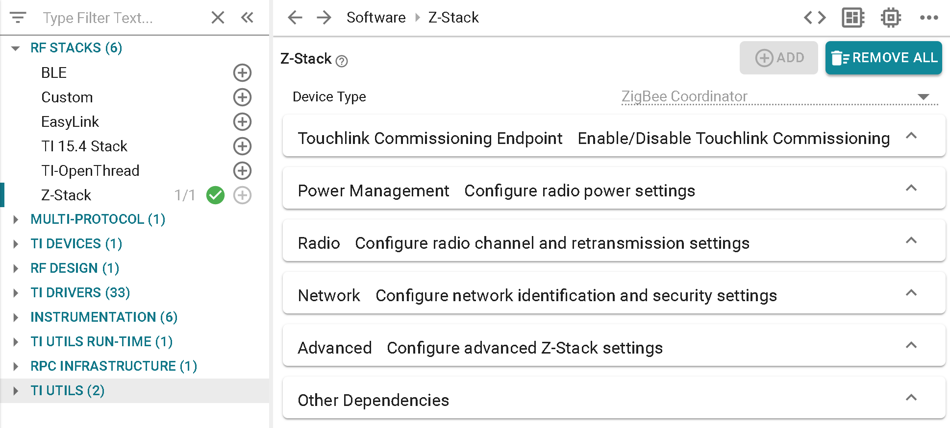
Device Type and Power Management Configuration
Standard Zigbee Device
The Device Type (Coordinator, Router, End Device, Network Processor) is pre-determined for each example project and cannot be changed. The Power Mode of Operation (see End Device) and multiple poll period (see Child Management) are only configurable for End Device and ZNP projects.
Green Power Device
The device type is Green Power Device. The Green Power Device Configuration section shows all of the definitions which are configured with this project type.
Touchlink Commissioning Endpoint
Standard Zigbee Device
Allows the ability to enable Touchlink Commissioning of a ZED or ZR role for either the Initiator or Target modes (see Touchlink Commissioning)
Radio Configuration
Standard Zigbee Device
The basic Radio parameters to consider for the Zigbee stack include primary and secondary channel mask selection (Configuring Channel). This is also where the TX power output can be selected and the internal Power Amplifier (PA) is enabled if applicable (Power Configuration).
Green Power Device
Configure the channel which the GPD will operate on and the TX power it will use.
Network Configuration
Standard Zigbee Device
The network configurations involve basic Zigbee network settings, such as the PAN ID (Configuring the PAN ID and Network to Join), extended PAN ID (Extended PAN IDs), default network and TC link keys (Security), and End Device Timeout (Child Management). Joining devices can also select the distributed global link key (Distributed Security Network) whereas routing devices have a maximum device list option (Network Configurations). Routing devices can select the number of devices allowed to directly associate and coordinators can determine the maximum number of TCLK entries stored (For Trust Center (TC) Devices).
Green Power Device
Green Power Device Type determines what function the GPD embodies in the network (eg. switch, temperature sensor, etc). Green Power Device ID Type determines how the GPD identifies itself (eg. Configurable GPD ID, IEEE address). If Configurable GPD ID is selected, the developer may choose a 32-bit ID which the GPD will use (Green Power Device).
Security Configuration
Green Power Device
Security settings which are specific towards Green Power devices, such as level and key type, and key, which are further discussed in Green Power Security.
Advanced Configuration
Standard Zigbee Device
The advanced configuration parameters require in-depth knowledge of the Zigbee network operation. They are separated into different sections for joining (Miscellaneous), routing (Routing Protocol), data polling (Portable Devices), packet sending (End-to-End Acknowledgements), and maximum table sizes (Network Address Assignment). Several of these settings are also explained in Network Configurations.
Green Power Device
Data Frame Retries determines how many times the GPD will transmit each packet. Auto-commissioning determines whether the GPD will set the auto-commissioning bit in the packets (Commissioning a Green Power Device). Radio Receive After Transmit determines whether the GPD should expect to receive a packet after transmitting. Sequence Number Capability determines whether the GPD will use sequential MAC sequence numbers (Green Power Data Frames (GPDF)).
Adjust Your Application
When you have finished adjusting the parameters, save the .syscfg file.
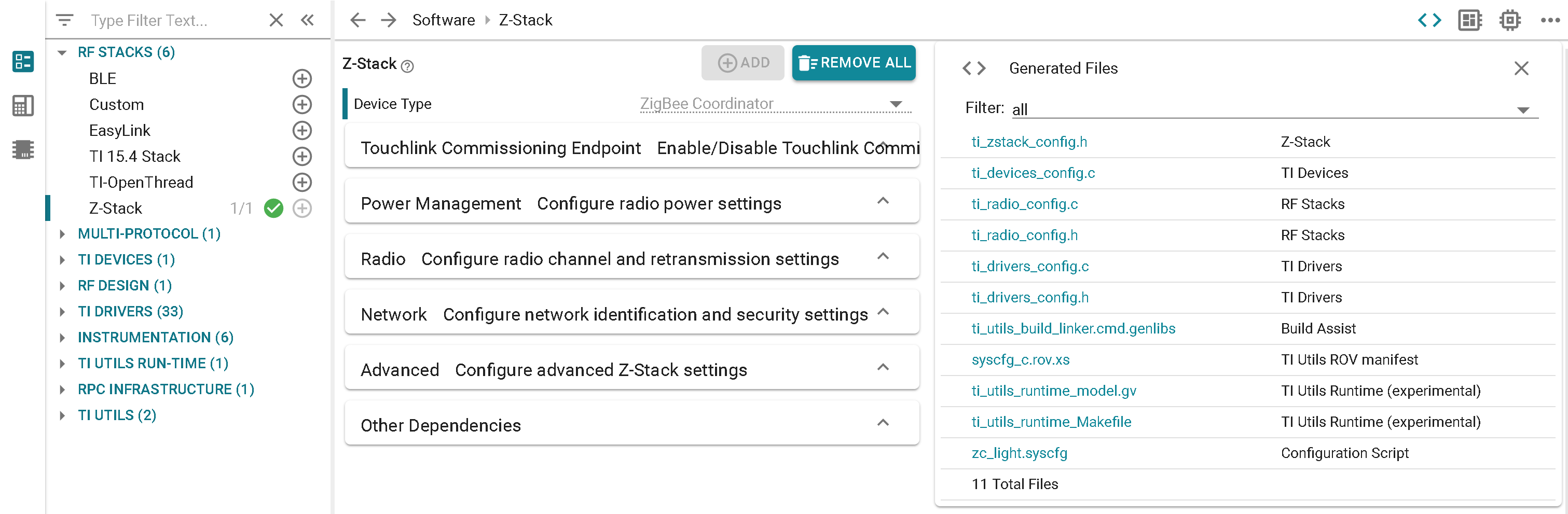
You can preview the files which will be generated by clicking the <> symbol. In this example,
ti_devices_config.c, ti_drivers_config.c/h, and ti_zstack_config.h were generated respectively
by the TI DEVICES, TI DRIVERS, and RF STACKS → Z-Stack views.
If you are using the System Configuration stand-alone tool, you will have to
import every generated file to your IDE. For the SysConfig CCS plug-in,
you can generate all the files by building your project. After the build has
completed, you will find the generated files in the output folder of your project,
called default/syscfg. All parameters configured in the Zigbee view of
SysConfig will result in a #define in ti_zstack_config.h alongside other macros
which are not included in SysConfig.
Attention
Whenever you re-build the project, SysConfig will re-generate the files.
Because of this, any changes made directly to ti_zstack_config.h will be overwritten.
Application Builder
The Zigbee Application Builder is an extension of SysConfig whose purpose is to kick-start development of a Zigbee application using TI’s Z-Stack. It is designed to save developers time with setting up the specific ZCL characteristics of the Zigbee application endpoint so that they can quickly begin adding unique functionality to the application itself.
Note
Please refer to ZCL Specification documentation from the Zigbee Alliance when attempting to determine what qualifications are necessary to pass Zigbee endpoint certification.
To start the SampleApp example which features the Zigbee Application Builder,
import the following project into CCS or IAR:
examples/rtos/<development board>/zstack/<zc/zed/zr>_sampleapp
The Zigbee Application Builder can be located in SysConfig through RF STACKS
→ Z-Stack → Zigbee Application Endpoint. After building the project,
additional zcl_config.c/h files will be created alongside the other
generated files. These replace the zcl_sample*_data.c file that exists
in other Z-Stack example projects. For instructions on further developing
applications using these generated settings, refer to
Customizing Application Builder Functionality.
Note
Currently, it is not possible to add multiple Zigbee Application Endpoints
in SysConfig. If a developer wishes to combine two certifiable Zigbee device
types into one application, it is recommended that they reference a separate
SampleApp project from which the second device type is selected inside the
SysConfig Application Builder. That way the generated zcl_config.c/h
files from this second project can easily be transferred as application files
for the first project.
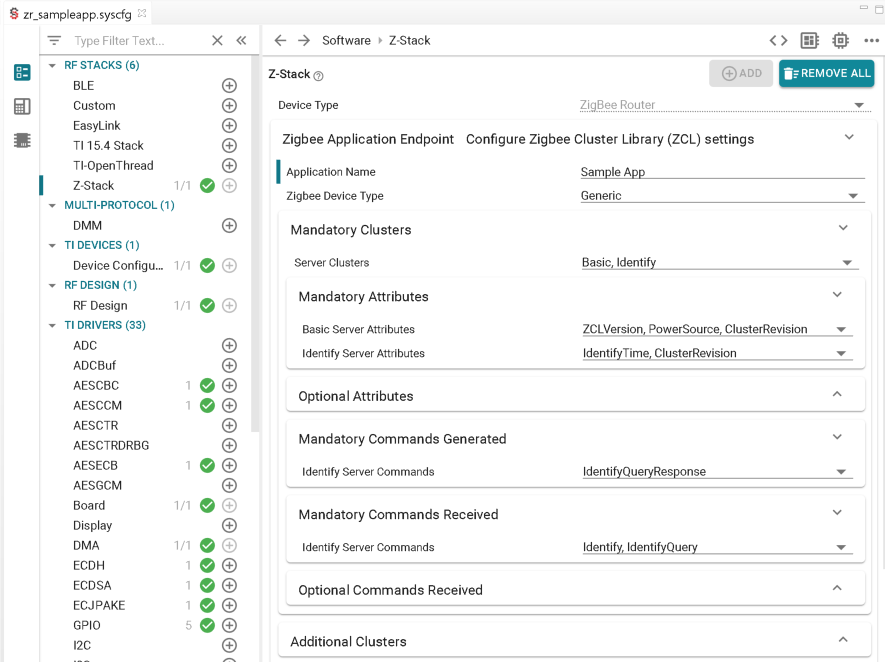
Application Name and Zigbee Device Type
The application name must be alphanumeric, starting with a letter, and can include
spaces. It is used as a starting point for most of the variables
(ex. SAMPLEAPP_ENDPOINT) and functions
(ex. sampleApp_ResetAttributesToDefaultValues) declared in
zcl_config.h and zcl_config.c.
The Zigbee device type drop-down menu establishes the default settings for the other Application Builder SysConfig submodules. The options provided are common devices which can be certified with Zigbee 3.0 clusters. Developers are given the option to configure additional attributes, commands, or clusters as seen fit for their application. By selecting Generic it is possible to use a blank configuration, in which case only the Basic and Identify server clusters are used as they are mandatory for certification. Any further clusters would be added under the Additional Clusters menu.
Mandatory Clusters
These include the server and client clusters and their corresponding attributes/commands required to pass Zigbee endpoint certification. It is therefore highly recommended that no mandatory clusters, attributes, or commands be removed. It is still possible to add Optional Attributes & Commands Generated/Received to the mandatory clusters generated, however these do not need to be supported for certification.
Additional Clusters
Additional clusters required for the end application which exist outside of the default configuration of the Zigbee Device Type selected can be added here. After a cluster is chosen, the Mandatory/Optional Attributes & Commands Generated/Received submodules will appear to allow for further modifications. There are some optional additional clusters recommended per device type by the Zigbee Alliance, but these do not have to be supported for the device to become certified.
BDB Reporting
Whenever a cluster which supports BDB Reporting (ex. OnOff or TemperatureMeasurement) is selected, this submodule appears. Max Analog Attribute Size represents the most bytes for which an analog attribute can be reported. This value affects the Reportable Change range, which specifies the minimum amount of change in the attribute’s value required to trigger the sending of a report so long as this event occurs inside the Maximum/Minimum Reporting Interval window. If the Minimum Reporting Interval time has not yet been surpassed since the last report then the action will be delayed until this requirement is fulfilled. The value can be set at 0x0000 to disable the minimum limit. If the Maximum Reporting Interval time occurs since the last report then one will be sent automatically. If set to 0x0000 then periodic reporting will be disabled.
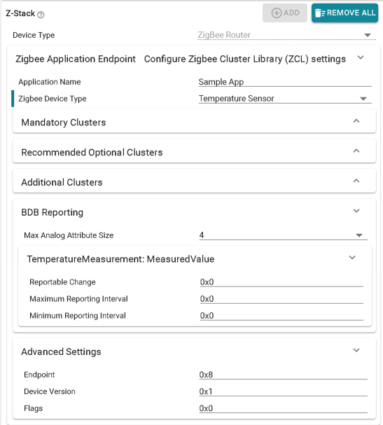
Advanced Settings
Endpoint specifies the endpoint used within the node. 0x00 is not allowed as it is reserved for the Zigbee Device Object (ZDO) and values between 0xF1 and 0xFE are not recommended unless approved by the Zigbee Alliance. Device Version is a 4-bit value that specifies the version of the device description supported on this endpoint and Flags contain any manufacturer-specific values, both of which are displayed in the simple descriptor.
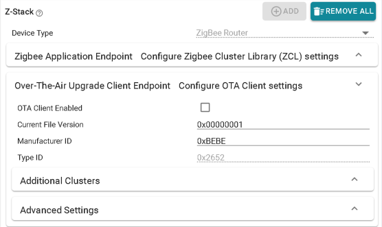
Over-The-Air Upgrade Client Endpoint
For developers wishing to build upon the SampleApp example to include over-the-air download capabilities, an Over-The-Air Upgrade Client Endpoint module is also provided inside SysConfig. This serves the same purpose as the Zigbee Application Endpoint but pertains to the OTA endpoint instead of the application itself. Besides enabling functionality through selecting OTA Client Enabled, specific values for Current File Version and Manufacturer ID can be configured. Type ID cannot be altered as it is pre-determined by the project version imported and SimpleLink device being used. For further information on integrating OTA into an application, please refer to Adding Client Functionality to an Application.