SysConfig Migration
If you have an existing CC13xx or CC26xx software project and you want to start developing with SysConfig, follow the steps below. This guide assumes you have a stack project from the SimpleLink CC13xx or CC26xx 2.40 SDK or newer. If this is not the case, please look at the Stack Porting Guides to see how to update to SimpleLink CC13xx or CC26xx 2.40 SDK.
Note
If you are starting development with a fresh project, you don’t need to migrate from non-SysConfig to SysConfig-enabled project. In SimpleLink CC13xx/CC26xx SDK v. 2.40 and later, SysConfig-enabled projects are found in the syscfg_preview folder.
1. Add a .syscfg File to Your Project
In this guide, we will start with a EasyLink project, then apply necessary changes to start using SysConfig.
You can use the standalone SysConfig tool to make this file. Please see the SysConfig Standalone Installer Download Page.
- Choose the “Start a new Design” option. Choose your device, part and package.
For the
productpath, add the following for your SDK:{SDK_INSTALL_DIR}\.metadata\product.json. - Add an RF stack according to your existing project (EasyLink). Add any TI Drivers configuration that your project requires. If applicable, add one or more Radio Configuration. You can find guidelines for configuring each of these in the Get started with SysConfig chapter.
- Save the file and add it to your project.
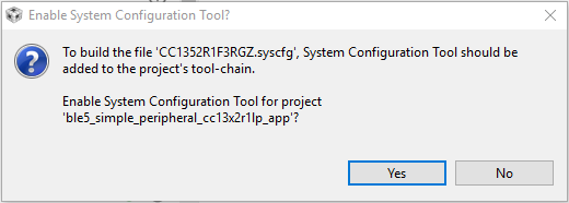
If you are using CCS, you can add the file by dragging it into your CCS workspace. When you add the file, the following dialog box will appear and allow you to add SysConfig to your project:
If you are using IAR, follow the steps in Using SysConfig with IAR Workbench before you
add the .syscfg file. The steps for adding the file are as follows:
- Include the .syscfg file you want to use in the project (right click on the project → Add Files → Navigate to the .syscfg file and add it).
- Create a custom build step: Right click on project → Options → Custom Build → Populate the following:
| Option | Populate with the following: |
| File Name Extensions | .syscfg |
| Command Line | $SYSCONFIG_ROOT$/nw/nw.exe $SYSCONFIG_ROOT$/dist/cli.js -o $PROJ_DIR$ -s “$ COM_TI_SIMPLELINK_CC13XX_CC26XX_SDK_INSTALL_DIR$/.metadata/product.json” –compiler iar $FILE_PATH$ |
| Output files (one per line) | SysConfig_Generated_Files.ipcf |
| Run this tool before all other tools | Checked |
2. Add SysConfig Options
If you are using CCS, open the Project Properties and do the following:
- In System Configuration Tool → Basic Options → Name of the board file
(-b, –board), set it to
/ti/boards/.meta/<BOARD_NAME>. (E.g., if you are using a CC1312R LaunchPad, set the name to/ti/boards/.meta/CC1312R1_LAUNCHXL). It is not necessary to set the name of the device. - In System Configuration Tool → Basic Options → Root system config
meta data file in a product or SDK (-s, –product), add
${COM_TI_SIMPLELINK_CC13XX_CC26XX_SDK_INSTALL_DIR}/.metadata/product.json.
3. Remove Board Files From Your Project
These are not needed as the board configuration is done in SysConfig. E.g. if
you are using a CC1352R LaunchPad, delete the Board.h,
CC1352R1_LAUNCHXL.h, and CC1352R1_LAUNCHXL.c from the project. If your
project contains board files ending with *_fxns.c or *.cmd, don’t
delete them.
You can see how to configure your board files and TI driver instances with
SysConfig in Configure The Board Files with SysConfig. If you’re not exactly sure what
peripherals are on your board and you have a TI development board, you can check
the .syscfg file from an existing syscfg project for your board. E.g.
if you’re using a CC26X2R LaunchPad board, you can check the .syscfg file
in one of the projects in ${COM_TI_SIMPLELINK_CC13XX_CC26XX_SDK_INSTALL_DIR}
/examples/rtos/CC26X2R1_LAUNCHXL.
4. Migrate smartrf_settings
All radio settings are controlled by SysConfig. You can see how to set them in Adding RF Settings.
Delete the smartrf_settings folder in your project, including the
smartrf_settings files.
When you have finished doing all the changes, you can compare your old
smartrf_settings files to the SysConfig generated files found in the
output folder of the example (ti_radio_config.c/h).
5. Migrate easylink_config
The settings in easylink_config can all be set by SysConfig. Please see
EasyLink Configuration for instructions on this.
Delete the easylink_config files in the project. (Don’t delete the
EasyLink files.) When you have finished doing all the changes, you can
compare your old easylink_config files to the SysConfig generated files
found in the output folder of the example ((ti_easylink_config.c/h).
6. SysConfig Migration Tool
This is a guide for device migrations that require manual steps. The board switch should be performed in sysconfig before following the steps below.
CC1352R1 to CC26x2
RF Drivers Example Migration:
- Acknowledge/dismiss error in the RF Stacks module
- Add Custom PHY Setting for Proprietary 2400 - 2480 MHz band
- In Code Export Configuration for the custom PHY, select Legacy for the Symbol Name Generation Method
- Enable Use Multi-Protocol Patch option (for rfPacketErrorRate example)
Easylink Example Migration:
- Acknowledge/dismiss error in the RF Stacks module
CC26X2 to CC1352R1
RF Drivers Example Migration:
rfPacketErrorRate:
Add the following PHYs in the RF Stacks module for the Proprietary 779 - 930 MHz frequency band: 50 kbps, 5 kbps, 200 kbps, and Custom PHY Setting.
For each added PHY:
- Change TX Power in PHY Properties to below 14 dBm
- In Code Export Configuration, select Custom as the Symbol Name Generation Method (select Legacy for Custom PHY)
- Enable Use Multi-Protocol Patch option
- Use symbol names for RF driver examples list in this document to make sure RF Command Symbols and Other Symbols in sysconfig are named properly. This does not apply to Custom PHY.
Other RF drivers examples:
No extra steps are needed for migration.
Easylink Example Migration:
rfEasyLinkNp:
Add the following PHYs in the RF Stacks module: 50 kbps, 5 kbps, 200 kbps, and Custom PHY Setting.
For each added PHY:
- Change TX Power in PHY Properties to below 14 dBm
Other Easylink Examples:
- Change TX Power in PHY Properties to below 14 dBm. To keep 14 dBm TX power, enable Force VDDR in the Device Configuaration module.
CC1312 to CC1352R1
RF Drivers Example Migration:
rfPacketErrorRate:
Add the following PHYs in the RF Stacks module for Proprietary 2400 - 2480 MHz frequency band: 100 kbps, 250 kbps, Bluetooth 5 LE 1M PHY (If migrating rfPacketErrorRate)
For each PHY displaying a warning:
- Change TX Power in PHY Properties to below 14 dBm
- In Code Export Configuration, select Custom as the Symbol Name Generation Method
- Enable ‘Use Multi-Protocol Patch’ option
- Modify the names of RF Command Symbols and Other Symbols in sysconfig based on the symbol names for RF driver examples list in this document. This does not apply to Custom PHY.
Other RF drivers examples:
No extra steps are needed for migration.
Easylink Example Migration:
rfEasyLinkNp:
Add the following PHYs in the RF Stacks module: 100 kbps, 250 kbps
For each PHY displaying a warning:
- Change TX Power in PHY Properties to below 14 dBm
Other Easylink Examples:
- Change TX Power in PHY Properties to below 14 dBm. To keep 14 dBm TX power, enable Force VDDR in the Device Configuaration module
CC1352P-4 to CC1352P1
RF Drivers Example Migration:
Please note that the PHY being used will not carry over to the CC1352P1 if it is 433 MHz.
- Select LAUNCHXL-CC1352P1 for the RF Design
- Remove PHYs for Proprietary 420 - 527 MHz frequncy band
- Add the following PHYs in the RF Stacks module for Proprietary 779 - 930 MHz band (only add one if not migrating rfPacketErrorRate): 50 kbps, 5kbps, 200 kbps, Custom PHY Setting.
- For each sub-1GHz PHY:
- Enable High PA
- In Code Export Configuration, select Custom as the Symbol Name Generation Method (select Legacy for Custom PHY)
- Select ‘Combined PA table’ for ‘PA Table Export Method’
- Enable ‘Use Multi-Protocol Patch’ option
- Modify the names of RF Command Symbols and Other Symbols in sysconfig based on the symbol names for RF driver examples list in this document. This does not apply to Custom PHY.
Easylink Example Migration:
Select LAUNCHXL-CC1352P1 for the RF Design
This step is only needs to be performed if migrating the rfEasyLinkNp example
- Add the following PHYs in the RF Stacks module, if not already selected: 50 kbps, 5kbps, 200 kbps, Custom PHY Setting
CC13X2R to CC1352P
RF Drivers Example Migration:
rfPacketErrorRate:
Make sure the correct board is selected for the RF design. For example, if migrating to CC1352P-2 then select LAUNCHXL-CC1352P-2 for the RF design
If migrating to CC1352P4, remove all selected PHYs for Proprietary 779 - 930 MHz in the RF Stacks module. For Proprietary 420 - 527 MHz add 5 kbps, 50kbps, and Custom PHY Setting.
For each of the PHYs that are selected, do the following:
Acknowledge/dismiss any error stating ‘An attempt was made here to change settings that do not exist…’
- In the Code Export Configuration section, select Combined PA table for PA Table Export Method
- Select Custom for the Symbol Name Generation Method (select Legacy for Custom PHY)
- Make sure RF Command Symbols and Other Symbols are named properly based on symbol names for RF driver examples list in this document. This does not not apply to Custom PHY.
- If migrating to LAUNCHXL-CC1352P-2, High PA can be enabled for the BLE PHY. If migrating to LAUNCHXL-CC1352P1, High PA can be enabled in PHY Properties for 50 kbps, 5kbps, and 200 kbps PHYs
Other RF drivers examples:
- Make sure the correct board is selected for the RF design. For example, if migrating to CC1352P-2 then select LAUNCHXL-CC1352P-2 for the RF design
- High PA can be enabled if corresponding PHY is selected for the P device. For example, if Custom PHY is selected for 868 MHz band then High PA can be enabled if migrating to CC1352P1
- If migrating to CC1352P4, please note that the 868 MHz band is not supported for this device
Easylink Example Migration:
rfEasyLinkNp:
Make sure the correct board is selected for the RF design. For example, if migrating to CC1352P-2 then select LAUNCHXL-CC1352P-2 for the RF design
Selecting correct antenna switch
- Open RF module options
- Open Use Hardware
- Select SKY13317-373LF RF Antenna Switch
If migrating to CC1352P-2, select TX power under 14 dBm for sub-1GHz PHYs
If migrating to CC1352P4, remove 200kbps PHY from RF Stacks module
Other Easylink Examples:
Make sure the correct board is selected for the RF design. For example, if migrating to CC1352P-2 then select LAUNCHXL-CC1352P-2 for the RF design
Selecting correct antenna switch
- Open RF module options
- Open Use Hardware
- Select SKY13317-373LF RF Antenna Switch
Disable Force VDDR in Device Configuration module when migrating to CC1352P1 or CC1352P4
Symbol Names for RF Driver Examples:
The list for each PHY specifies the correct name that should be used for each symbol when using an RF drivers example.
Bluetooth 5, LE 1M PHY:
- CMD_FS: RF_ble_cmdFs
- CMD_BLE5_RADIO_SETUP: RF_ble_cmdRadioSetup
- CMD_BLE5_ADV_AUX: RF_ble_cmdBle5AdvAux
- CMD_BLE5_GENERIC_RX: RF_ble_cmdBleGenericRx
- CMD_BLE_ADV_NC: RF_ble_cmdBleAdvNc (Add CMD_BLE5_ADV_NC to the RF Command List if it is not already selected)
- RF Mode Symbol Name: RF_modeBle
- TX Power Table Symbol Name: RF_BLE_txPowerTable
- TX Power Table Size Symbol Name: RF_BLE_TX_POWER_TABLE_SIZE
- Overrides Table Symbol Name: pOverrides_ble
5 kbps, SimpleLink Long Range:
- CMD_FS: RF_cmdFs_sl_lr
- CMD_PROP_RADIO_DIV_SETUP: RF_cmdPropRadioDivSetup_sl_lr
- CMD_PROP_TX: RF_cmdPropTx_sl_lr
- CMD_PROP_RX: RF_cmdPropRx_sl_lr
- RF Mode Symbol Name: RF_prop_sl_lr
- TX Power Table Symbol Name: PROP_RF_txPowerTable_sl_lr
- TX Power Table Size Symbol Name: RF_PROP_TX_POWER_TABLE_SIZE_SL_LR
- Overrides Table Symbol Name: pOverrides_sl_lr
50 kbps, 2-GFSK:
- CMD_FS: RF_cmdFs_fsk_50kbps
- CMD_PROP_RADIO_DIV_SETUP: RF_cmdPropRadioDivSetup_fsk_50kbps
- CMD_PROP_TX: RF_cmdPropTx_fsk_50kbps
- CMD_PROP_RX: RF_cmdPropRx_fsk_50kbps
- RF Mode Symbol Name: RF_prop_fsk_50kbps
- TX Power Table Symbol Name: RF_PROP_txPowerTable_fsk_50kbps
- TX Power Table Size Symbol Name: RF_PROP_TX_POWER_TABLE_SIZE_fsk_50kbps
- Overrides Table Symbol Name: pOverrides_fsk_50kbps
200 kbps, 2-GFSK:
- CMD_FS: RF_cmdFs_fsk_200kbps
- CMD_PROP_RADIO_DIV_SETUP: RF_cmdPropRadioDivSetup_fsk_200kbps
- CMD_PROP_TX: RF_cmdPropTxAdv_fsk_200kbps
- CMD_PROP_RX: RF_cmdPropRxAdv_fsk_200kbps
- RF Mode Symbol Name: RF_prop_fsk_200kbps
- TX Power Table Symbol Name: RF_PROP_txPowerTable_fsk_200kbps
- TX Power Table Size Symbol Name: RF_PROP_TX_POWER_TABLE_SIZE_fsk_200kbps
- Overrides Table Symbol Name: pOverrides_fsk_200kbps
100 kbps, 2-GFSK:
- CMD_FS: RF_cmdFs_2_4G_fsk_100kbps
- CMD_PROP_RADIO_DIV_SETUP: RF_cmdPropRadioDivSetup_2_4G_fsk_100kbps
- CMD_PROP_TX: RF_cmdPropTx_2_4G_fsk_100kbps
- CMD_PROP_RX: RF_cmdPropRx_2_4G_fsk_100kbps
- RF Mode Symbol Name: RF_prop_2_4G_fsk_100kbps
- TX Power Table Symbol Name: RF_PROP_txPowerTable_2_4G_fsk_100kbps
- TX Power Table Size Symbol Name: RF_PROP_TX_POWER_TABLE_SIZE_2_4G_fsk_100kbps
- Overrides Table Symbol Name: pOverrides_2_4G_fsk_100kbps
250 kbps, 2-GFSK:
- CMD_FS: RF_cmdFs_2_4G_fsk_250kbps
- CMD_PROP_RADIO_DIV_SETUP: RF_cmdPropRadioDivSetup_2_4G_fsk_250kbps
- CMD_PROP_TX: RF_cmdPropTx_2_4G_fsk_250kbps
- CMD_PROP_RX: RF_cmdPropRx_2_4G_fsk_250kbps
- RF Mode Symbol Name: RF_prop_2_4G_fsk_250kbps
- TX Power Table Symbol Name: RF_PROP_txPowerTable_2_4G_fsk_250kbps
- TX Power Table Size Symbol Name: RF_PROP_TX_POWER_TABLE_SIZE_2_4G_fsk_250kbps
- Overrides Table Symbol Name: pOverrides_2_4G_fsk_250kbps
Reference
Parameters that no longer have to be set at run-time and can be configured
statically in SysConfig. These settings take affect when EasyLink_init is
called:
- Address Filtering
- Address Size
- Radio Inactivity timeout
- Multi-client mode
- Asynchronous Rx Timeout
Map of defines in ti_easylink_config.h to configurables in the EasyLink module:
| EASYLINK_DEFAULT_ADDR | TX Settings → Transmit Address |
| EASYLINK_USE_DEFAULT_ADDR | Automatically set when TX Settings → Transmit Address is changed |
| EASYLINK_MAX_DATA_LENGTH | Max Data Length (bytes) |
| EASYLINK_ADDRESS_SIZE | Address Size (bytes) |
| EASYLINK_ENABLE_ADDR_FILTERING | RX Settings → Enable Address Filtering |
| EASYLINK_ADDR_FILTER_TABLE | RX Settings → Addresses to Filter On (comma separated) |
| EASYLINK_NUM_ADDR_FILTER | Automatically updated to the number of addresses in RX Settings → Addresses to Filter On (comma separated) |
| EASYLINK_IDLE_TIMEOUT | Radio Inactivity Timeout (ms) |
| EASYLINK_ENABLE_MULTI_CLIENT | Advanced Settings → Enable Multi-Client Mode |
| EASYLINK_ASYNC_RX_TIMEOUT | RX Settings → Asynchronous Rx Timeout (ms) |
| EASYLINK_MIN_CCA_BACKOFF_WINDOW | TX Settings → CCA Settings → Minimum Backoff Window Multiplier. (Note that the value generated in easylink_config.h is the log base 2 of the value found in the TX Settings → CCA Settings → Minimum Backoff Window Multiplier drop-down) |
| EASYLINK_MAX_CCA_BACKOFF_WINDOW | TX Settings → CCA Settings → Maximum Backoff Window Multiplier. (Note that the value generated in easylink_config.h is the log base 2 of the value found in the TX Settings → CCA Settings → Maximum Backoff Window Multiplier drop-down) |
| EASYLINK_CCA_BACKOFF_TIMEUNITS | TX Settings → CCA Settings → Backoff Time Units (us) |
| EASYLINK_CS_RSSI_THRESHOLD_DBM | TX Settings → CCA Settings → RSSI Threshold (dBm) |
| EASYLINK_CHANNEL_IDLE_TIME_US | TX Settings → CCA Settings → Channel Idle Time (us) |
| EASYLINK_PARAM_CONFIG | .ui32ModType: Radio Settings → Default PHY |
| .pClientEventCb: Advanced Settings → Client Event Callback Function | |
| .nClientEventMask: Advanced Settings → Client Event Mask | |
| .pGrnFxn: TX Settings → CCA Settings → Random Number Generation Function |