Introduction
The purpose of this document is to describe the Texas Instruments Inc. (TI) vendor specific Host Controller Interface (HCI) for Bluetooth® low energy (BLE). This document is intended for customer product software engineers and field application engineers working with the TI BLE stack software.
Functional Overview
In BLE, there is a logical distinction between the Host software (often referred to as the higher layer stack) and the Controller software as shown in Fig. 1.
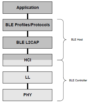
Fig. 1 BLE Protocol Stack Layers
These components can either exist on the same device (single-device configuration), or be placed on separate devices (dual-device configuration) utilizing a Host Controller Interface (HCI) for communication (see section 7 for more detail). In the single-device configuration, there is obviously only one device, and the application software would execute on top of the BLE profiles and stack (see Fig. 2).

Fig. 2 Single Device Configuration
In the dual-device configuration, the application software would also execute on top of the BLE profiles and stack, and only the controller would be located on a separate device (see :num_ref:’dual-device’). This configuration is not supported by the TI BLE-Stack since both the Host and Controller components of the BLE protocol stack reside on the wireless MCU.
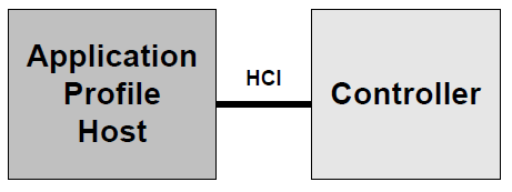
Fig. 3 Dual Device Configuration
However, allowing an application to be developed on one device, while communicating with the BLE stack executing on another, enables access to the BLE stack that would not normally be available (see :num_ref:’network-processor’).
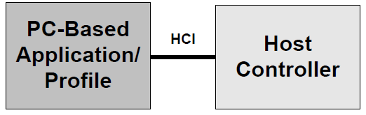
Fig. 4 Network Processor Configuration with HCI
This configuration provides is a very convenient configuration for creating a test development environment where the “application” is actually a test tool that can execute scripts, generate logs, etc. Note however that the HCI as defined by Bluetooth only allows Controller commands and events. As such, a set of Vendor Specific commands and events will be used instead, and that is what this document intends to convey.
Numerical Notation Conventions
Multiple-octets may be specified in hexadecimal notation in one of two ways:
Standard Hexadecimal Notation
In this notation, a single hexadecimal radix indicator “0x” precedes the entire value. The octet order as read from left to right is from most significant octet to least significant octet. For example, for the value 0x123456ABCDEF, ’12’ is the most significant octet and ‘EF’ is the least significant octet.
Colon Separated Hexadecimal Notation
In this notation, the hexadecimal radix indicator “0x” is not used and octets are colon separated. The octet order as read from left to right is from least significant octet to most significant octet. For example, for the value 12:34:56:AB:CD:EF, ’12’ is the least significant octet and ‘EF’ is the most significant octet.
Definitions, Abbreviations, Acronyms
glossary needs to be added for enxt release.
Revision History
2017-10-10: v 4.0: BLE5 V1.1 Added Command for Advertising extension.