Overview
This section describes the high level design and functionality of the Micro BLE Stack. The Micro BLE Stack enables applications on the CC13x2 or CC26x2 to advertise, scan, or behave as an connection monitor. The Micro BLE stack utilizes the MultiMode RF driver as well. The MultiMode RF Driver enables dual-mode applications where another communication protocol stack is integrated and utilized along side the Micro BLE Stack.
Constraints and Requirements
The Micro BLE Stack has the following internal constraints and requirements:
- This design optionally depends on partial integration of ICall to save system resources if there already is an application using ICall in the dual-mode use case. In the case of using the ICall module, ICall’s system heap management and TI-RTOS service abstraction will be used.
- There is no HCI because there is no separation between the controller and the host.
- The privacy feature is not supported, but random address generation is supported
- To minimize the memory overhead and remove redundant context switching, the Micro BLE Stack doesn’t have a separate TI-RTOS task. It is instead integrated in the application task.
- The micro stack requires the use of the MultiMode RF driver
Connection Monitor Limitations
Connection Monitor feature has the following limitations:
- Connections must use LE Channel Selection Algorithm #1
- Connections must use LE 1M PHY
- Connections must exist on LE Data channels
System Architecture
The Micro BLE Stack consists of the Micro Link Layer (Micro LL or uLL), Micro Generic Access Profile (Micro GAP or uGAP), and a Micro Radio Interface (Micro RFI or uRFI).
The uLL is mainly responsible for maintaining the device state and scheduling radio commands to perform advertising operations. The pre- and post-processing for each radio command execution are also done by the uLL. The uLL directly invokes the RF Driver and will utilize the MicroRFI to initialize the radio for the Micro BLE Stack features being exercised.
Micro LL performs:
- Radio management
- Device state management between standby, advertising/scanning, and monitoring
The uGAP sits between the uLL and the application and is mainly responsible for controlling the uLL to set up and run a profile role. The application can indirectly configure the uLL through uGAP and be notified of events from uLL through uGAP callbacks. uGAP needs TI-RTOS because the clock/timer service is used.
Micro GAP performs:
- Broadcaster role
- Connection Monitor feature
- Initialization and configuration of the Micro LL
- State Management within the role/feature
- Interfacing with the application
The uRFI is primarily used to initialize the Radio and allow Radio commands to be sent. Depending on the features enabled the uRFI will define the proper parameter structures which the uLL will externally reference to utilize the RF driver.
Micro BLE Stack is not designed to run as a separate TI-RTOS task, in order to save memory that would otherwise be required to maintain an additional task. Instead, it is integrated in the application, from TI-RTOS context’s point of view, so that all the application callbacks that are originated from RF and Clock SWIs in the Micro BLE Stack and might have lengthy operations such as command completion post processing and error handling are called in the application task context. How the Micro BLE Stack is integrated context-wise in the application is illustrated in Figure 125. Note that only the subcomponents directly relevant to the Micro BLE Stack in the application and the RF driver are depicted.
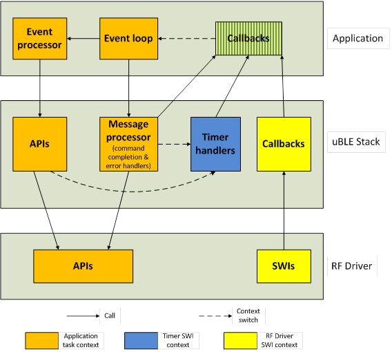
Figure 125. System Context Diagram