CMD_PROP_RX_ADV
cmd_prop_rx vs cmd_prop_rx_adv
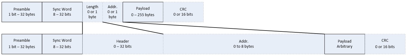
The main differences between the packet format supported by the CMD_PROP_RX and the CMD_PROP_RX_ADV commands are the Header field and the Address field.
The below table shows the difference between the cmd_prop_rx and cmd_prop_rx_adv commands:
| CMD_PROP_RX | CMD_PROP_RX_ADV |
|---|---|
| RF_cmdPropRx.commandNo = 0x3802, | RF_cmdPropRxAdv.commandNo = 0x3804, |
| RF_cmdPropRx.status = 0x0000, | RF_cmdPropRxAdv.status = 0x0000, |
| RF_cmdPropRx.pNextOp = 0, | RF_cmdPropRxAdv.pNextOp = 0, |
| RF_cmdPropRx.startTime = 0x00000000, | RF_cmdPropRxAdv.startTime = 0x00000000, |
| RF_cmdPropRx.startTrigger.triggerType = 0x0, | RF_cmdPropRxAdv.startTrigger.triggerType = 0x0, |
| RF_cmdPropRx.startTrigger.bEnaCmd = 0x0, | RF_cmdPropRxAdv.startTrigger.bEnaCmd = 0x0, |
| RF_cmdPropRx.startTrigger.triggerNo = 0x0, | RF_cmdPropRxAdv.startTrigger.triggerNo = 0x0, |
| RF_cmdPropRx.startTrigger.pastTrig = 0x0, | RF_cmdPropRxAdv.startTrigger.pastTrig = 0x0, |
| RF_cmdPropRx.condition.rule = 0x1, | RF_cmdPropRxAdv.condition.rule = 0x1, |
| RF_cmdPropRx.condition.nSkip = 0x0, | RF_cmdPropRxAdv.condition.nSkip = 0x0, |
| RF_cmdPropRx.pktConf.bFsOff = 0x0, | RF_cmdPropRxAdv.pktConf.bFsOff = 0x0, |
| RF_cmdPropRx.pktConf.bRepeatOk = 0x0, | RF_cmdPropRxAdv.pktConf.bRepeatOk = 0x0, |
| RF_cmdPropRx.pktConf.bRepeatNok = 0x0, | RF_cmdPropRxAdv.pktConf.bRepeatNok = 0x0, |
| RF_cmdPropRx.pktConf.bUseCrc = 0x1, | RF_cmdPropRxAdv.pktConf.bUseCrc = 0x1, |
| RF_cmdPropRx.pktConf.bVarLen = 0x1, | |
| RF_cmdPropRx.pktConf.bChkAddress = 0x0, | |
| RF_cmdPropRxAdv.pktConf.bCrcIncSw = 0x0, | |
| RF_cmdPropRxAdv.pktConf.bCrcIncHdr = 0x1, | |
| RF_cmdPropRx.pktConf.endType = 0x0, | RF_cmdPropRxAdv.pktConf.endType = 0x0, |
| RF_cmdPropRx.pktConf.filterOp = 0x0, | RF_cmdPropRxAdv.pktConf.filterOp = 0x0, |
| RF_cmdPropRx.rxConf.bAutoFlushIgnored = 0x0, | RF_cmdPropRxAdv.rxConf.bAutoFlushIgnored = 0x0, |
| RF_cmdPropRx.rxConf.bAutoFlushCrcErr = 0x0, | RF_cmdPropRxAdv.rxConf.bAutoFlushCrcErr = 0x0, |
| RF_cmdPropRx.rxConf.bIncludeHdr = 0x1, | RF_cmdPropRxAdv.rxConf.bIncludeHdr = 0x1, |
| RF_cmdPropRx.rxConf.bIncludeCrc = 0x0, | RF_cmdPropRxAdv.rxConf.bIncludeCrc = 0x0, |
| RF_cmdPropRx.rxConf.bAppendRssi = 0x0, | RF_cmdPropRxAdv.rxConf.bAppendRssi = 0x0, |
| RF_cmdPropRx.rxConf.bAppendTimestamp = 0x0, | RF_cmdPropRxAdv.rxConf.bAppendTimestamp = 0x0, |
| RF_cmdPropRx.rxConf.bAppendStatus = 0x1, | RF_cmdPropRxAdv.rxConf.bAppendStatus = 0x0, |
| RF_cmdPropRx.syncWord = 0x930B51DE, | RF_cmdPropRxAdv.syncWord0 = 0x930B51DE, |
| RF_cmdPropRxAdv.syncWord1 = 0x00000000, | |
| RF_cmdPropRx.maxPktLen = 0xFF, | RF_cmdPropRxAdv.maxPktLen = 0x00FF, |
| RF_cmdPropRxAdv.hdrConf.numHdrBits = 0x8, | |
| RF_cmdPropRxAdv.hdrConf.lenPos = 0x0, | |
| RF_cmdPropRxAdv.hdrConf.numLenBits = 0x8, | |
| RF_cmdPropRxAdv.addrConf.addrType = 0x0, | |
| RF_cmdPropRxAdv.addrConf.addrSize = 0x0, | |
| RF_cmdPropRxAdv.addrConf.addrPos = 0x0, | |
| RF_cmdPropRxAdv.addrConf.numAddr = 0x0, | |
| RF_cmdPropRx.address0 = 0xAA, | |
| RF_cmdPropRx.address1 = 0xBB, | |
| RF_cmdPropRxAdv.lenOffset = 0x00, | |
| RF_cmdPropRx.endTrigger.triggerType = 0x1, | RF_cmdPropRxAdv.endTrigger.triggerType = 0x1, |
| RF_cmdPropRx.endTrigger.bEnaCmd = 0x0, | RF_cmdPropRxAdv.endTrigger.bEnaCmd = 0x0, |
| RF_cmdPropRx.endTrigger.triggerNo = 0x0, | RF_cmdPropRxAdvendTrigger.triggerNo = 0x0, |
| RF_cmdPropRx.endTrigger.pastTrig = 0x0, | RF_cmdPropRxAdv.endTrigger.pastTrig = 0x0, |
| RF_cmdPropRx.endTime = 0x00000000, | RF_cmdPropRxAdv.endTime = 0x00000000, |
| RF_cmdPropRxAdv.pAddr = 0, | |
| RF_cmdPropRx.pQueue = 0, | RF_cmdPropRxAdv.pQueue = 0, |
| RF_cmdPropRx.pOutput = 0 | RF_cmdPropRxAdv.pOutput = 0 |
How to use length information
Case 1: 1 byte length after sync word.
A packet that can be received by using CMD_PROP_RX using variable length has the length byte placed directly after the sync word. To be able to receive this using CMD_PROP_RX_ADV the following fields must be set:
RF_cmdPropRxAdv.pktConf.bCrcIncHdr = 0x1;       // The CRC is calculated over the length byte + the payload
RF_cmdPropRxAdv.hdrConf.numHdrBits = 0x8;       // The header is 1 byte wide
RF_cmdPropRxAdv.hdrConf.numLenBits = 0x8;       // The length is 1 byte (no other info in header)
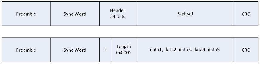
Case 2: 3 byte header, length information not directly after sync word.
With the advanced RX command, it is possible to receive packets with a length byte that is longer than 8 bits, and the length information does not have to be located at the start of the header. Consider the packet shown in the figure below being transmitted on the air, where the header is 3 bytes, and the length byte is the two last bytes of the header:
To be able to receive this packet, and interpret the length correctly, the following must be set:
RF_cmdPropRxAdv.hdrConf.numHdrBits      = 0x18;         // The header is 3 bytes wide
RF_cmdPropRxAdv.hdrConf.numLenBits      = 0x10;         // The length is 2 bytes
RF_cmdPropRxAdv.hdrConf.lenPos          = 0x00;         // The length starts at bit position 0
Case 3: 3 byte header, length information directly after sync word.
Consider the packet shown in the figure below being transmitted on the air, where the header is 3 bytes, and the length byte is the two last bytes of the header:
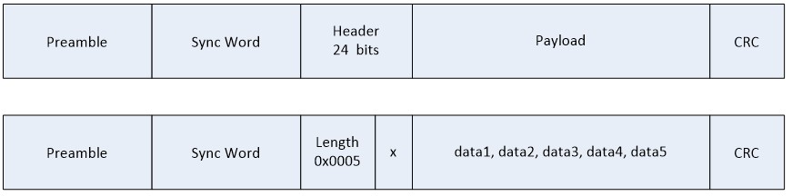
The packet will be stored in the receive buffer as shown below:
0xXX, 0x05, 0x00, data1, data2, data3, data4, data5
To be able to receive this packet, and interpret the length correctly, the following must be set:
RF_cmdPropRxAdv.hdrConf.numHdrBits      = 0x18; // The header is 3 bytes wide
RF_cmdPropRxAdv.hdrConf.numLenBits      = 0x10; // The length is 2 bytes
RF_cmdPropRxAdv.hdrConf.lenPos          = 0x08; // The length starts at bit position 8
Case 4: 3 byte header, length includes CRC
The radio interprets the length information to be the number of bytes to be received between the Header and the CRC. This is not necessarily the case. Consider the packet in Figure z
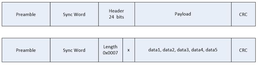
In this case, the packets length information gives the total number of bytes received after the Header, including the CRC (2 bytes). To account for this, the signed number .lenOffset can be added to the received length to give the number of bytes after the header and before the CRC. In the case above, .lenOffset should be -2:
RF_cmdPropRxAdv.hdrConf.numHdrBits      = 0x18; // The header is 3 bytes wide
RF_cmdPropRxAdv.hdrConf.numLenBits      = 0x10; // The length is 2 bytes
RF_cmdPropRxAdv.hdrConf.lenPos          = 0x08; // The length starts at bit position 8
RF_cmdPropRxAdv.lenOffset                       = 0xFE; // Add -2 to the length info to exclude the CRC bytes
How to do address filtering
Assume the following packet:
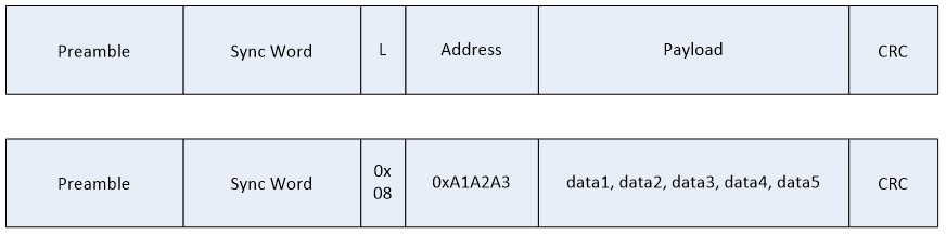
One length byte is sent, followed by a 3 bytes long address. There are several ways the receiver can be configured to receive this packet.
Case 1: The length and address is part of the header
RF_cmdPropRxAdv.pktConf.bCrcIncHdr      = 0x1;  // The CRC is calculated over the header + the payload
RF_cmdPropRxAdv.hdrConf.numHdrBits      = 0x20; // The header is 4 bytes wide
RF_cmdPropRxAdv.hdrConf.numLenBits      = 0x8;  // The length is 1 byte
RF_cmdPropRxAdv.hdrConf.lenPos          = 0x18; // The length is the first header byte received
                                                                                        // but will be stored last in the receive buffer
The transmitted length gives the number of bytes after the length byte, excluding the CRC. The receiver needs to know the number of bytes between the header and the CRC, so the .lenOffset is set to -3:
RF_cmdPropRxAdv.lenOffset                       = 0xFD; // Add -3 to the length info to exclude the 3 address bytes

RF_cmdPropRxAdv addrConf.addrType       = 0x1;  // Address is part of the header
RF_cmdPropRxAdv.addrConf.addrSize       = 0x18; // Address is 24 bits
RF_cmdPropRxAdv.addrConf.addrPos        = 0x0;  // The address starts at bit position 0
RF_cmdPropRxAdv.addrConf.numAddr        = 0x1;  // 1 address in the address list
RF_cmdPropRxAdv.pAddr = (uint8_t*)&addressList;

static uint32_t addressList[] =
{
        0xA1A2A3,
};
It is possible to add more addresses to the address list:
static uint32_t addressList[] =
{
        0xA1A2A3,
        0xB1B2B3,
        0xC1C2C3,
};

RF_cmdPropRxAdv.addrConf.numAddr = 0x3; //   3 addresses in the address list
The receiver will then accept packets with all 3 addresses, and addressInd (Bit 0-4 in the received status byte) will indicate which address was received. To append the status byte to the payload:
.rxConf.bAppendStatus = 0x1
Case 2: Address as part of payload
The address can also be consider to be part of the payload and not the header
RF_cmdPropRxAdv.pktConf.bCrcIncHdr              = 0x1;  // The CRC is calculated over the header byte + the payload
RF_cmdPropRxAdv.hdrConf.numHdrBits      = 0x8;  // The header is 1 byte wide
RF_cmdPropRxAdv.hdrConf.numLenBits      = 0x8;  // The length is 1 byte
Since the address is no longer part of the header, .lenOffset must be set back to 0:
RF_cmdPropRxAdv.lenOffset               = 0x0

RF_cmdPropRxAdv addrConf.addrType       = 0x0; // Address comes after the header
RF_cmdPropRxAdv.addrConf.addrSize       = 0x3; // Address is 3 bytes
RF_cmdPropRxAdv.addrConf.numAddr        = 0x1; // 1 Address in the address list

RF_cmdPropRxAdv.pAddr = (uint8_t*)&addressList;
As mentioned earlier, the header is stored using little-endian byte order to the receive buffer. This is not the case when the address is not part of the header. The address in the address list must therefore be swapped:
static uint32_t addressList[] =
{
        0xA3A2A1,
};
Case 3: Use of 2 sync words and address filtering
The advanced RX command has two sync word fields (syncWord0 and syncWord1). If one of the following conditions is fulfilled
- syncWord1 ≠ 0 and addrConf.addrType = 1
- syncWord1 ≠ 0, addrConf.addrType = 0, and addrConf.addrPos ≠ 0
one extra bit identifying the sync word is concatenated with the address as the MSB.
Assume that syncWord1 ≠ 0 and addrConf.addrType = 1:
RF_cmdPropRxAdv.pktConf.bCrcIncHdr              = 0x1;  // The CRC is calculated over the header + the payload
RF_cmdPropRxAdv.hdrConf.numHdrBits      = 0x20; // The header is 4 bytes wide
RF_cmdPropRxAdv.hdrConf.numLenBits      = 0x8;  // The length is 1 byte
RF_cmdPropRxAdv.hdrConf.lenPos          = 0x18; // The length is the first header byte received but
                                                                                                // will be stored last in the receive buffer
RF_cmdPropRxAdv.lenOffset               = 0xFD; // Add -3 to the length info to exclude
                                                // the 3 address bytes
RF_cmdPropRxAdv addrConf.addrType       = 0x1;  // Address is part of the header
RF_cmdPropRxAdv.addrConf.addrSize       = 0x18; // Address is 24 bits
RF_cmdPropRxAdv.addrConf.addrPos        = 0;    // The address starts at bit position 0
RF_cmdPropRxAdv.addrConf.numAddr        = 0x2;  // 2 addresses in the address list

RF_cmdPropRxAdv.pAddr = (uint8_t*)&addressList;

static uint32_t addressList[] =
{
        0x00A1A2A3, // syncWord0 + Address 0xA1A2A3
        0x01A1A2A3, // syncWord1 + Address 0xA1A2A3
};
Sending the packet with syncWord0: addressInd = 0 and syncWordId = 0 Sending the packet with syncWord0: addressInd = 1 and syncWordId = 1
If setting the address list to:
static uint32_t addressList[] =
{
        0x01A1A2A3, // syncWord1 + Address 0xA1A2A3
};

RF_cmdPropRxAdv.addrConf.numAddr        = 0x1;
Then only packets with syncWord1 will be received, and addressInd = 0 and syncWordId = 1