Time synchronization over the air
In a network of multiple devices, it is often required that all participants operate on a common time base. This document describes how to synchronize multiple CC13x0 devices using the proprietary PHY.
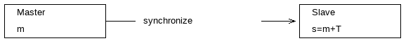
In our example we have a master and a slave and we want to synchronize the
slave clock to the master’s clock. Both clocks run at the same tick rate, but
the slave clock has an initial offset  relative to the master.
Assuming that
relative to the master.
Assuming that  and
and  specify absolute timestamps with
index
specify absolute timestamps with
index  on the master and the slave, respectively, we get the
relationship:
on the master and the slave, respectively, we get the
relationship:
(1)
Initially, the slave doesn’t know and hence, is always
different from the master’s time .
As the timer domain, we choose the radio timer RAT on the RF core which provides 32 bit timestamps at 4 MHz (4 ticks per µs). RAT timestamps can be used as absolute start and end triggers for radio operation commands.
One-way synchronization example
In order to get , it would be enough to send one message at a
timestamp  from the master to the slave as shown in the sequence
chart below:
from the master to the slave as shown in the sequence
chart below:
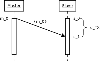
Figure 31. Sequence chart of the one-way time synchronization process.
The slave would receive the message after a certain delay
 at
at  and could deduce by the
following formula:
and could deduce by the
following formula:
(2)
is the time of the receiver signal Syncword found. The
transmission offset contains the time to bring up the RF
front-end, to calibrate the synthesizer and to send the packet preamble and
the syncword. The time of flight (TOF) is very small compared to that value
and can be ignored. is a fixed value and depends on the
chosen RF settings. It must be measured/only once during development and is
then compiled into the application.
A two-way synchronization algorithm
This section describes an indirect approach that doesn’t require to measure
. But it can also be used to deduce
indirectly. We use an algorithm similar to the Network Time
Protocol.
The following sequence diagram shows the synchronization process.
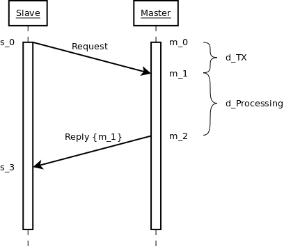
Figure 32. Sequence chart of the two-way time synchronization process.
The slave sends a synchronization request to the master at  and
sets as an absolute start trigger for the TX command.
and
sets as an absolute start trigger for the TX command.
The master receives the message after at  .
This is the timestamp that is appended as meta data to the packet and
specifies the time when the sync word was found:
.
This is the timestamp that is appended as meta data to the packet and
specifies the time when the sync word was found:
(3)
After a short time  , the master responds to the
request with a reply message at
, the master responds to the
request with a reply message at  . It sets the TX command start
trigger to and includes into the packet payload as
well:
. It sets the TX command start
trigger to and includes into the packet payload as
well:
(4)
When the client receives the reply at  , it has the following timing
information and can calculate the initial clock offset :
, it has the following timing
information and can calculate the initial clock offset :
- : Request sent by the client
- : Request received by the master
- : Reply received by the client
- : A fixed delay for message processing on the master
From (1), we know that:
(5)
We do not know , but we know its offset to which is :
(6)
(7)
We still do not know , but we know that it is included
into the round-trip time  as follows:
(8)
With the help of (8) we can rewrite (7) to:
(9)
and finally obtain . This value must now be added to any further RF
operation on the client.
Sending and receiving timestamp messages
This section provides code snippets for implementing the above algorithms.
When sending a timestamp message at a certain time, we use txTimestamp as
an absolute start trigger, but include it also into the packet payload:
// Convenience macro
#define RF_convertMsToRatTicks(milliseconds) \
    (((uint32_t)(milliseconds)) * 1000 * 4)

// Exported from SmartRF Studio
rfc_CMD_PROP_TX_t txCommand;

// Set a time in the near future (5ms)
uint32_t txTimestamp = RF_getCurrentTime() + RF_convertMsToRatTicks(5);

// Set txTimestamp as an absolute start trigger
txCommand.startTrigger.triggerType = TRIG_ABSTIME;
txCommand.startTime = txTimestamp;

// Include it also into the payload
uint32_t payload[1] = { txTimestamp };
txCommand.pPkt = (uint8_t*)&payload[0];
txCommand.pktLen = sizeof(payload);
When receiving this packet, the receiver must read the timestamp from the
packet payload, but must also configure the RF core to append a timestamp to
each received packet. This is the time when the RF core raises the signal
“Synchronization found” and we choose the name rxTimestamp:
// Exported from SmartRF Studio
rfc_CMD_PROP_RX_t rxCommand;
// Append RX timestamp to the payload
RF_cmdPropRx.rxConf.bAppendTimestamp = 1;
// The code to execute the RX command and to setup
// the RX data queue is not shown here.
// When reading the packet content from the
// RX data queue, rxTimestamp is behind the payload:
rfc_dataEntryGeneral_t* currentDataEntry = RFQueue_getDataEntry();
// Assuming variable length
uint8_t packetLength = *(uint8_t*)(¤tDataEntry->data);
uint8_t* packetDataPointer = (uint8_t*)(¤tDataEntry->data + 1);
uint32_t rxTimestamp;
memcpy(&rxTimestamp, &packetDataPointer + packetLength, 4);
// The TX timestamp is found in the payload
uint32_t txTimestamp;
memcpy(&rxTimestamp, packetDataPointer + packetLength, 4);