5.2. Servo Drive Demo - User Guide
5.2.1. Overview
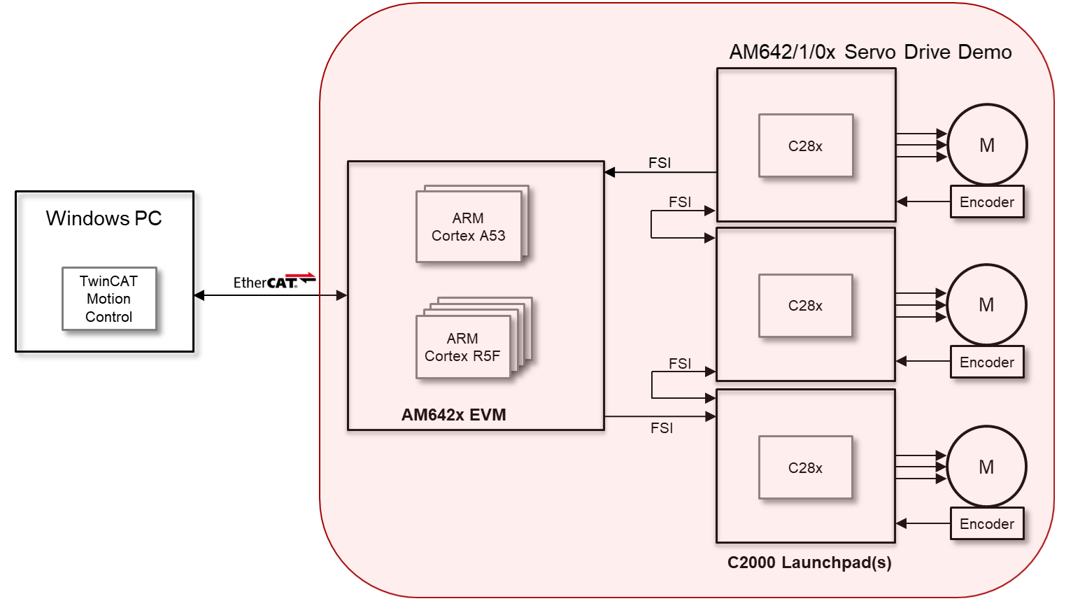
The Servo Drive Demo showcases the AM64x device’s ability to support a real-time servo control path by taking EtherCAT CiA402 input and performing a position/speed loop calculation and sending torque and flux reference values to a C2000 device over the FSI interface.
5.2.2. Hardware Prerequisites
Windows PC with TwinCAT
Main Node:
- TI AM64x GP EVM and power supply
- TI FSI serial interface (FSI) adapter board: TMDSFSIADAPEVM
3x Seconary Nodes, for each Seconary Node:
- TI F280049 Launchpad: LAUNCHXL-F280049C
- TI FSI serial interface (FSI) adapter board: TMDSFSIADAPEVM
- TI GaNFET BoosterPack: BOOSTXL-3PHGANINV
- TI Low voltage servo motor: LVSERVOMTR
- 24 volt power supply that can be plugged into the screw terminals of the GaNFET BoosterPack
- Stand-offs for assembling LaunchPad, BoosterPack, and FSI adapter boards via 0.1 inch (2.54 mm) pitch headers on each board
Cables not included in above mentioned hardware kits:
- Ethernet patch cable (PC to AM64x EVM RJ45)
- 1x USB micro-B plug to USB-A plug cable (PC to AM64x UART)
- 1x USB micro-B plug to USB-A plug cable, or external emulator (PC to AM64x JTAG)
SD card (minimum 8 GB) for MMCSD boot, not required for OPSI boot
5.2.3. Hardware Configuration
5.2.3.1. Hardware Jumper & Switch Settings
Each Secondary Node comprises three hardware boards: an F280049 LaunchPad, an FSI adapter board, and a GaNFET BoosterPack. The jumper settings are identical for the boards in each node. Please see the following sections of [1] for details on the jumper settings:
- LaunchPad: Section 3.1.2 LAUNCHXL-F280049C
- BoosterPack: Section 3.1.3 BOOSTXL-3PHGANINV
- FSI Adapter Board: Section 3.1.5 TMDSFSIADAPEVM
The Main Node hardware includes the AM64x EVM and an FSI Adapter Board.
- The AM64x EVM jumpers can be left in their default configuration.
- The Main Node FSI Adapter Board jumper settings are the same as those in a Secondary Node, except a jumper should be placed on J5 Pin1-2. This is so power is supplied to the adapter board from the FSI bus. See [2], Table 2 for details.
The EVM Switch settings for different boot modes are shown in the table below.
| Boot Mode | SW2(12345678) | SW3(12345678) |
|---|---|---|
| No Boot | 11011111 | 00000000 |
| SD Boot | 11000010 | 01000000 |
| OSPI Boot | 11001110 | 01000000 |
Refer to the AM64x EVM Hardware Users Guide for more information on the AM64x EVM.
5.2.3.2. Secondary Node Hardware Assembly
The Secondary Nodes are assembled by connecting 0.1 inch (2.54 mm) pitch headers on the boards. These connections are easily realized using tall stackable standoffs with female headers and two rows of pins. The following picture shows these type of standoffs which have been cut to fit the headers on the boards.
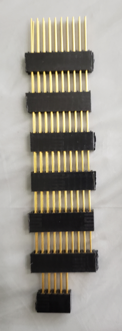
Fig. 5.1 Stackable Standoffs
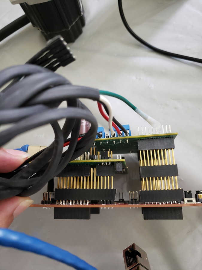
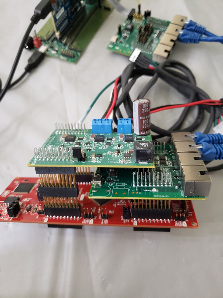
To assemble the hardware for each Secondary Node:
- Connect the FSI Adaptor Board to the LaunchPad: J3 <-> J5/J7, J3 <-> J6/J8, and J1 <-> J11.
- Connect BoosterPack to LaunchPad: J1/J3 <-> J1/J3 and J2/J4 <-> J2/J4.
The pictures below show an assembled Seconary Node from both sides.
5.2.4. Hardware Connections
Motor connections to LaunchPad & BootsterPack, see the following figures in [1]:
- Motor to LaunchPad: Figure 14. Layout of LAUNCHXL-F280049C and Switches Setting
- Motor to BoosterPack: Figure 15. Layout, Switches Setting and Wires Connection of BOOSTXL-3PHGANINV
- Power supply to BoosterPack: Figure 15. Layout, Switches Setting and Wires Connection of BOOSTXL-3PHGANINV
PC to AM64x EVM JTAG, select one of two options:
- On-board XDS110: USB micro-B plug to USB-A plug cable, micro B connector J28
- External: TI20 pin (J25) connector
PC to AM64x EVM, Ethernet: connect PC to EVM stacked RJ45 connector ICSSG PHY J21A or J21B using Ethernet patch cable
PC to AM64x EVM, UART: connect PC to EVM UARTs (FTDI) J26 using USB micro-B plug to USB-A plug cable
PC to F280049 LaunchPad: connect PC to each LaunchPad using USB micro-B plug to USB-A plug cable (included in LaunchPad kit). Provides LaunchPad power and on-board XDS110 JTAG connection.
FSI daisy chain connections : refer to [1] and diagram in Overview section above
- Connect each node in chain using 2x CAT5 T568B patch cable, 1 ft. (included in FSI Adapter Board kit)
- Connect Tx to Rx of next FSI Adapter Board in daisy chain
- Connect Rx to Tx of previous FSI Adapter Board in daisy chain
AM64x EVM to Main FSI Adapter Board Connections
| AM64x EVM Header:Pin | Pin Function | FSI Adapter Board Header:Pin | Pin Function | Notes |
|---|---|---|---|---|
| J7:P10 | 3V3 | J1:P10 | 3V3 | female-to-female jumper wire |
| J7:P6 | FSI_RX0_D0 | J1:P5 | RX_D0 | female-to-female jumper wire |
| J7:P5 | FSI_TX0_D0 | J1:P6 | TX_D0 | female-to-female jumper wire |
| J7:P3 | GND | J1:P3 | GND | female-to-female jumper wire |
| J7:P2 | FSI_RX0_CLK | J1:P1 | RX_CLK | female-to-female jumper wire |
| J7:P1 | FSI_TX0_CLK | J1:P2 | TX_CLK | female-to-female jumper wire |
AM64x EVM to C2000 BoosterPack Connections
| AM64x EVM Header:Pin | Pin Function | BoosterPack Header:Pin | Pin Function | Notes |
|---|---|---|---|---|
| J1:P9 | MCU_GPIO0_7 | J2:P13 | nENABLE | Active-Low Enable Signal for PWM buffer IC |
| J1:P23 | GROUND | J2:P20 | GROUND |
5.2.5. PC Software Setup
5.2.5.1. Code Composer Studio Setup
Setup of Code Composer Studio (CCS) for AM64x is documented here: CCS Setup for AM64x. It is strongly recommended to install the CCS version mentioned in these instructions.
The same version of CCS can be used for development on the F280049 Launchpad. To enable development on C2000 devices, select “C2000 real-time MCUs” in the “Select Components” window during CCS installation.
5.2.5.2. TwinCAT Setup
Download and install TwinCAT 3.1 Build 4024.7 or greater from Beckhoff.
Copy TI_ESC.xml file:
- from: %SDK%/rtos/pru_icss_ethercat_slave_01.00.09.08/protocols/ethercat_slave/ecat_appl/esi
- to: C:\TwinCAT\3.1\Config\Io\EtherCAT
Download & install “TwinCAT Project3.zip”:
- Available at the SDK download site separate from the installer.
- Unzip to desired location on C drive, e.g. C:\Users\%USERNAME%\Documents\TcXaeShell.
5.2.6. Executing Demo from Pre-Built Binaries
5.2.6.1. Flash Pre-Built Binaries to Main Node
The Servo Drive Demo uses the AM64x Secondary Boot Loader (SBL): AM64x SBL
Pre-built binares for SD and OPSI boot modes are provided for the AM64x EVM in folder apps/servo_drive_demo/prebuilt-images/AM64X.
OPSI boot: app, sysfw.bin & tiboot3.bin binaries are located in OSPIImage sub-folder.
- SD boot:
- app, sysfw.bin & tiboot3.bin binaries are located in SDCardImage sub-folder.
- The images should be copied to the root folder of an SD card, and the SD card should be placed in uSD card slot on the EVM.
The EVM boot switch settings are described in boot switch settings.
5.2.6.2. Flash Pre-Built Binaries to Secondary Nodes
Pre-built C2000 flash-mode binaries for each Secondary Node are contained in folder apps/servo_drive_demo/c2000_slave/am64x:
- Node 1: multi_axis_slave_node1_f28004x_cpu/F28004x_FLASH/multi_axis_slave_node1_f28004x_cpu.out
- Node 2: multi_axis_slave_node2_f28004x_cpu/F28004x_FLASH/multi_axis_slave_node2_f28004x_cpu.out
- Node 3: multi_axis_slave_node3_f28004x_cpu/F28004x_FLASH/multi_axis_slave_node3_f28004x_cpu.out
These binaries must be flashed to the Seconary Node 1, 2, and 3 LaunchPads in the FSI daisy chain.
One method of achieving this is if each LauchPad XDS110 can be distinguished within CCS via a unique XDS110 serial number. The existing serial numbers can be determined by executing the following at a DOS prompt:
<CCS install>/ccs/ccs_base/common/uscif/xds110/xdsdfu -e
If needed, the serial numbers can also be changed by using the xdsdfu tool with the -m and -s options. Execute xdsdfu without any options for further help, or see the xdsdfu documention in the same folder as xdsdfu.
Next create a target configuration for each node. Launch CCS and for each node:
- Select View -> Target Configurations
- In the Target Configurations Window, right-click “User Defined” and select “New Target Configuration”
- Select a unique name for the target configuration, e.g. TMS320F280049C_LaunchPad_N<x>.ccxml for Node x
- For Connection, select “Texas Instruments XDS110 USB Debug Probe”
- For Board of Device, select “TMS320F280049C”
- Under “Advanced Setup”, click on Target Configuration, and then “Texas Instruments XDS110 USB Debug Probe_0”
- Under “Debug Probe Selection”, choose “Select by Serial Number”
- In the “Enter the serial number” field, fill in the serial number obtained obtained from (or assigned using) xdsdfu.
After creating the target configurations, the pre-built C2000 binaries can be written to the TMS320F28004x on-chip flash. For each node LaunchPad:
- Right-click on node .ccxml in Target Configurations window
- Select “Launch Selected Configuration”
- In the Debug window, click on the C28xx_CPU1
- Select Run -> Connect Target
- Select Run -> Load -> Load Program
- Browse to the pre-built binary for the node, and click “OK”. This will write the flash with the binary.
5.2.6.3. Execute Demo
Follow the steps below to execute the demo.
1. Press the S1 XRSn reset button on the side of each Seconary Node. Reset the nodes in order 3, 2, 1.
2. Power cycle the AM64x EVM.
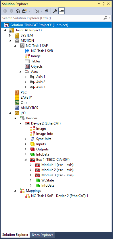
3. Launch TwinCAT XAE, and open the 3-axis Motor Control TwinCAT Project.
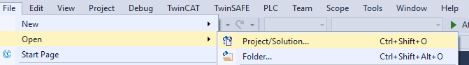
After the project is open, TwinCAT XAE will display the following:
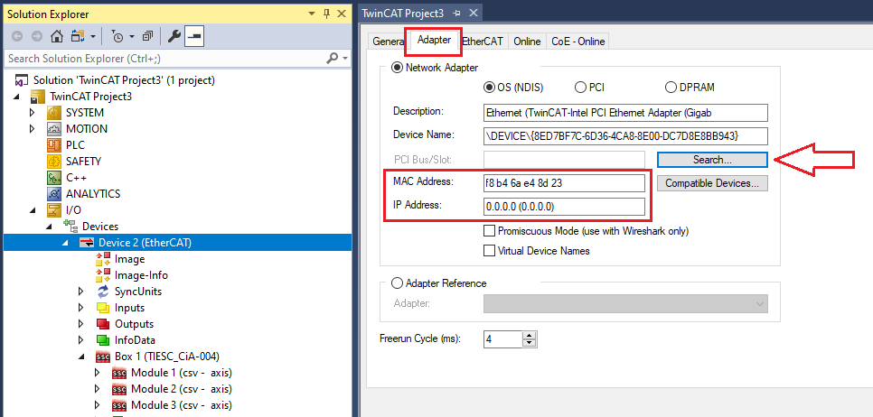
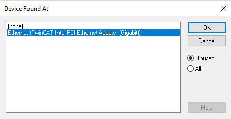
4. The first time the demo is executed, the EtherCAT MAC address must be updated. Update the MAC address as shown below.
5. Activate the configuration by clicking on the “Activate Configuration” button. Click “OK” when prompted whether to Restart TwinCAT System in Run mode.
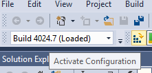
6. Ensure the device is in “OP” mode. If the device is not in “OP” mode, click on the “Activate Configuration” button again.
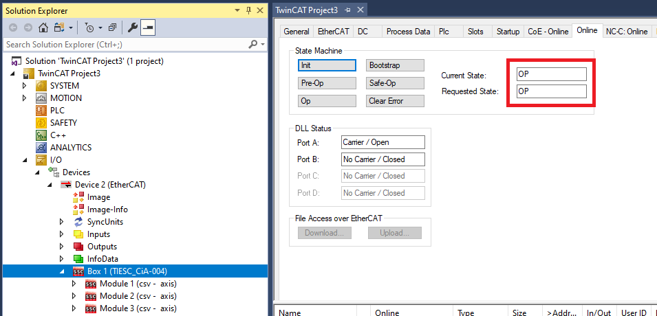
7. Select the target velocity for each axis.
Under I/O -> Devices -> Device 2 -> Box 1 (TIESC_CiA-004), expand Module 1, 2, and 3.
For Module 1, 2 and 3, expand Outputs.
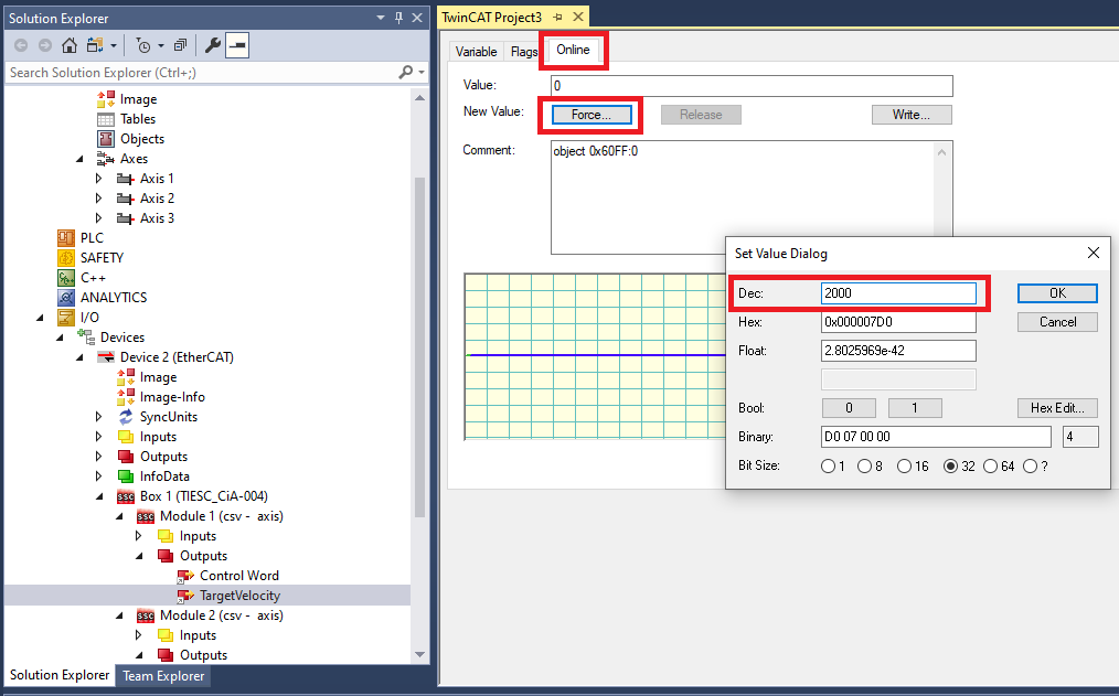
For each Module:
- Click on Target Velocity. Click the Online tab in the Project window, then click “Force” and set the target velocity for the axis (e.g. set “Dec” field to 2000).
- The target velocity for an axis can be changed whether an axis is enabled (see below) or not. To change the target velocity, click on “Force” and set a new target velocity.
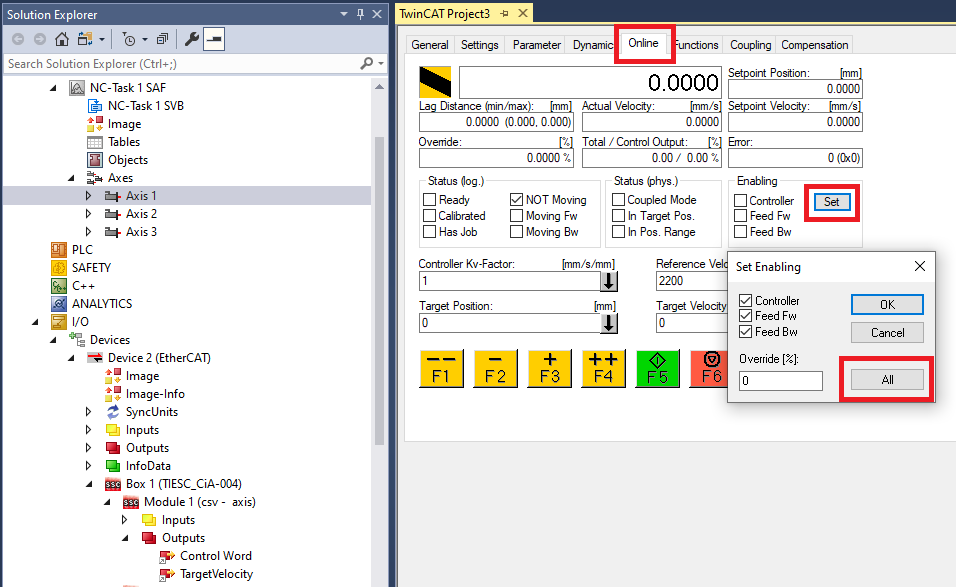
8. Enable each axis.
Expand MOTION -> Axes
For each Axis:
- Click the Online tab in the Project window, then click “Set”. Click on “All”, then “OK”.
- Once the axis is enabled, the motor should start spinning and feedback should be visible in the Online tab.
- The axis can be disabled/enabled by clicking “Set”, and then unchecking/checking the Controller switch.
5.2.7. Build & Execute Demo Software
5.2.7.1. Build & Execute AM64x Main Node Software
The Beckhoff EtherCAT stack must be downloaded separately from the Servo Drive Demo software. Instructions on downloading the EtherCAT stack and generating the stack source files are contained in the file apps/servo_drive_demo/ethercat_loop/beckhoff_ssc/README.txt.
After the EtherCAT stack files are placed in the correct folder, the Servo Drive Demo is built from the sitara-apps folder using the following commands:
- Linux: make common_libs servo_drive_demo BUILD_LINUX_APPS=0
- Windows: gmake common_libs servo_drive_demo BUILD_LINUX_APPS=0
The build outputs are described in the table below. All build outputs are located in folder apps/servo_drive_demo/out/AM64X (referred to as <OUT> in the table).
| No. | Core(s) | Build Output | Description |
|---|---|---|---|
| 1 | M4F_0 | <OUT>/M4F/NO_OS/release/app_no_os_m4f_0_servo_drive_safety.out |
|
| 2 | <OUT>/M4F/NO_OS/debug/app_no_os_m4f_0_servo_drive_safety.out |
|
|
| 3 | R5F_0_0 | <OUT>/R5F/SYSBIOS/release/app_tirtos_mcu1_0_servo_drive_ethcat.out |
|
| 4 | <OUT>/R5F/SYSBIOS/debug/app_tirtos_mcu1_0_servo_drive_ethcat.out |
|
|
| 5 | R5F_1_0 | <OUT>/R5F/NO_OS/release/app_no_os_mcu2_0_servo_drive_pscontrol.out |
|
| 6 | <OUT>/R5F/NO_OS/debug/app_no_os_mcu2_0_servo_drive_pscontrol.out |
|
|
| 7 | M4F_0, R5F_0_0, R5F_1_0 | <OUT>/OSPIImage | Application, SYSFW, and SBL release binaries for OSPI SBL boot. |
| 8 | <OUT>/SDCardImage | Application, SYSFW, and SBL release binaries for MMCSD SBL boot. |
To load and run executables (.out files) on the AM64x cores via CCS/JTAG, follow the procedures mentioned in Load Rtos & Baremetal Application Binaries Thru CCS.
The execute the Servo Drive Demo, follow the steps listed in Execute Demo. However, instead of booting from SD or OPSI, load the executables via JTAG after power cycling the AM64x EVM. When loading the executables, ensure the EVM boot settings are set for ‘No Boot’ mode (refer to boot switch settings).
5.2.7.2. Build & Execute C2000 Secondary Node Software
The C2000 code for the demo is provided here (v3.00.00.00 is used in the demo): MotorControl software development kit (SDK) for C2000 MCUs.
Install the C2000 MotorControl software, then launch CCS and import the Node 1, 2 and 3 CCS projects located in folder C2000Ware_MotorControl_SDK_3_00_00_00/solutions/tidm_02006_multi_axis_drive/f28004x/ccs/sensored_foc:
- multi_axis_slave_node1_f28004x_cpu.projectspec
- multi_axis_slave_node2_f28004x_cpu.projectspec
- multi_axis_slave_node3_f28004x_cpu.projectspec
Details on code modifications to apply to the installed C2000 code are contained in file apps/servo_drive_demo/c2000_slave/am64x/README.
The Flash and RAM binaries for each node can be built as follows:
- Right-click on project in Project Explorer
- Select Build Configurations -> Build All
To load and execute code on the a F280049 core via CCS/JTAG, follow the procedure mentioned in F280049 JTAG Load. Both RAM and Flash images can be loaded and executed using this procedure.
5.2.7.3. AM64x Main Node Software for System Development/Debug
Several R5F programs are provided for system debug, or for system development in the case not all Servo Drive Demo hardware is available (e.g. the Seconary Node hardware is unavailable). These programs can be built alongside the normal Main Node software by adding BUILD_DEBUG_TEST_TARGETS=1 to the build commands as below:
- Linux: make common_libs servo_drive_demo BUILD_LINUX_APPS=0 BUILD_DEBUG_TEST_TARGETS=1
- Windows: gmake common_libs servo_drive_demo BUILD_LINUX_APPS=0 BUILD_DEBUG_TEST_TARGETS=1
The table below provides a brief description of these programs and their intended use for system develpment and debug. All build outputs are located in folder apps/servo_drive_demo/out/AM64X (referred to as <OUT> in the table).
| No. | Core | Build Output | Description |
|---|---|---|---|
| 1 | R5F_0_0 | <OUT>/R5F/SYSBIOS/release/app_tirtos_mcu1_0_ethercat_emulation.out |
|
| 2 | <OUT>/R5F/SYSBIOS/debug/app_tirtos_mcu1_0_ethercat_emulation.out |
|
|
| 3 | <OUT>/R5F/SYSBIOS/release/app_tirtos_mcu1_0_mailbox_ipc_test.out |
|
|
| 4 | <OUT>/R5F/SYSBIOS/debug/app_tirtos_mcu1_0_mailbox_ipc_test.out |
|
|
| 5 | R5F_1_0 | <OUT>/R5F/NO_OS/release/app_no_os_mcu2_0_pslctrl_emulation.out |
|
| 6 | <OUT>/R5F/NO_OS/debug/app_no_os_mcu2_0_pslctrl_emulation.out |
|
|
| 7 | <OUT>/R5F/NO_OS/release/app_no_os_mcu2_0_mailbox_ipc_test.out |
|
|
| 8 | <OUT>/R5F/NO_OS/debug/app_no_os_mcu2_0_mailbox_ipc_test.out |
|
Additional system development and debug capability is supplied through a compile-time option for the R5F Position-Speed Loop program (Normal Build Images Table, No. 5 or 6). Specifically, this program can be built in FSI loopback mode. In this case, the Position-Speed Loop program loops FSI Tx traffic (normally sent to the Secondary Nodes over the FSI daisy chain) to FSI Rx. This is useful if the Secondary Node hardware is unavailable, or there is a desire to simplify Main Node code development by temporarily disconnecting the Secondary Node hardware.
The R5F Position-Speed Loop program can be built in FSI loopback mode by adding FSI_LOOPBACK=1 to the build commands as below. The resulting executable has the same folder and file name as the normal FSI build.
- Linux: make common_libs servo_drive_demo BUILD_LINUX_APPS=0 FSI_LOOPBACK=1
- Windows: gmake common_libs servo_drive_demo BUILD_LINUX_APPS=0 FSI_LOOPBACK=1
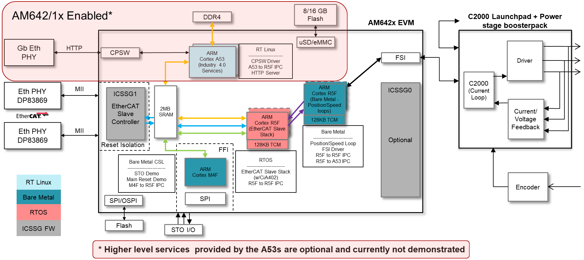
5.2.8. SW Architecture
The Servo Drive Demo was architected around a central real-time path that is made up of:
- ICSSG1 - EtherCAT Slave Controller firmware
- R5F0_0 - EtherCAT Slave Stack application implementing CiA402 using RTOS
- Mailbox IPC - Real-time, low-latency Interrupt based IPC between the two R5F cores
- R5F1_0 - Position Speed Loop application taking speed reference values from the EtherCAT master and converting them to torque and flux reference value for the C2000 running the current loop
- FSI - Low pin count, fast serial peripheral to send data to the C2000 device
This real-time path demonstrates the components needed to make up a bare-bones Servo Drive from receiving data from an EtherCAT master to sending the data to the device running the current loop to spin the motor. In addition to the real-time path the demo also aims to showcase the available M4F cores located in the AM64x device:
- M4F core - Runs in an isolated domain separate from the main domain cores (A53s and R5s). It monitors a user switch on the AM64x EVM and responds to the button press by resetting the main domain. The M4F stays alive due to isolation from reset.
The Software Architecture diagram is shown below:
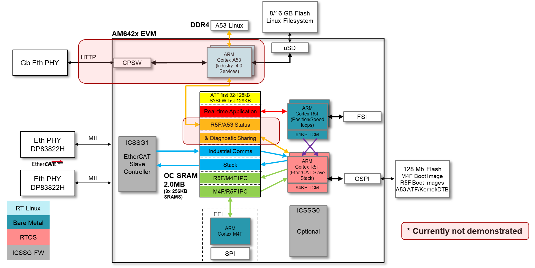
The software stack up in the demo is shown below:

5.2.9. Building Blocks
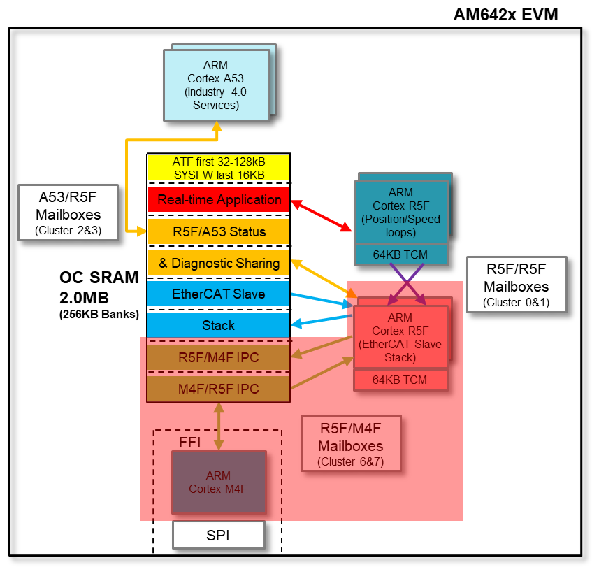
5.2.9.1. Memory Usage
On-chip SRAM bank partitioning
- AM64x architecture allows contention-free access to each SRAM bank
- Demo aims to be an example showing how to use static linker file partitioning to give each core/function its own SRAM space
- Suggested demo split pictured above
OSPI boot
- Fast boot option uses OSPI flash to store binaries
- AM64x EVM has a 128Mb OSPI flash on-board that will hold the M4F, R5F, and A53 binaries (excluding Linux filesystem - will be in eMMC or SD)
DDR4
- Expected to be used exclusively by A53/Linux. Not currently shown in the Servo Drive Demo
5.2.9.2. MCU Channel
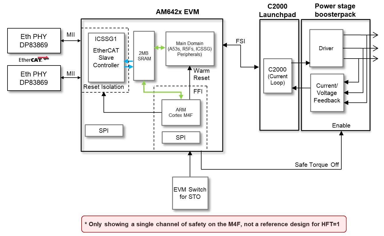
The M4 Application demo is broken into 3 main functions listed below:
- Main Domain monitoring and reset isolation
- M4 domain is reset isolated from Main domain so M4 application stays alive while rest of SoC reboots.
- ICSSG1 is also reset isolated from Main domain so industrial ethernet protocols with daisy chain stay connected while SoC reboots.
- SoC SRAM and DDR ECC Errors are monitored by M4 through ESM and a reset to the Main domain can be triggered in response.
- Montitor safe inputs and drive safe outputs
- The application demos a Safe Torque Off input using SW5 on the EVM. An external proximity detection device such as light curtain or mmWave radar can also be connected via MCU_GPIO0_6 on J1 (active-low input).
- M4 MCU_GPIO0_7 is the Safe Torque Off output which can be connected to GaNFET BoosterPack pin 13 (nEnable). This will disable the BoosterPack power stage and stop the motors.
- Black Channel communication path using OC SRAM
- Provide an example on the method to safely pass notifications and data between the main domain to the M4 core using a combination of the mailbox module and dedicated OC SRAM.
- Mimics data path recommended for FSoE data coming from the R5F running EtherCAT or HDSL Safety data coming from ICSSG0
5.2.9.3. Inter-Processor Communication (IPC)
The 2 methods of IPC needed in the demo are:
- R5F RTOS <-> R5F Bare metal
- Needed to pass real-time control data between the R5F cores
- Ultra-low latency needed
- R5F RTOS <-> M4F Bare metal
- Will act as an example for ‘Black Channel’ communication path
- SOC architecture and Functional Safety concerns dictate the method of passing information
5.2.9.3.1. R5F RTOS <-> R5F Bare Metal IPC
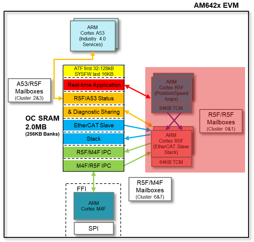
- Interrupt-based Mailbox CSL communication between R5F cores
- Dedicated mailbox clusters 0 and 1 used for message passing between R5F Pulsars
- Interrupts used to simplify programming and reduce wasted cycles on R5F
- Theoretical latency for 4 bytes transferred is 304-432ns (measured average is 410ns)
- Using direct VIM/VIC ISR registration (no software lookup of ISR function for each interrupt)
5.2.9.3.2. R5F RTOS <-> M4 Bare Metal IPC
Also uses Interrupt-based Mailbox CSL communication
- Information from the R5F needs to be passed to the M4
- Data (payload) placed into OC SRAM shared memory in dedicated SRAM bank
- M4 is notified that data is ready when the R5F uses mailbox to create an interrupt to the M4 core
- M4 retrieves the payload from OC SRAM
Does not violate Functional Safety use case since nothing from the Main Domain is pushed into the MCU Channel except for the Mailbox interrupt. M4 pulls the data from the Main Domain.
As long as a CRC accompanies the payload into the MCU channel before being checked, the ‘black channel’ is extended.
This path (and its reverse) will be used in future Safety application demonstrations such as Fail-safe over EtherCAT (FSoE) and HIPERFACE DSL Safety.
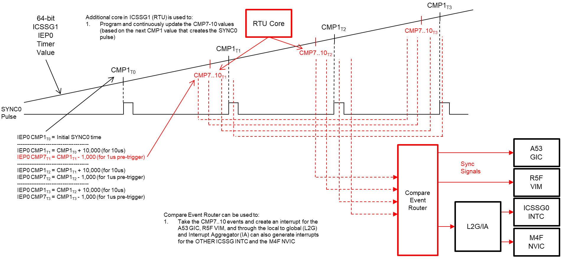
5.2.9.4. Demo Synchronization Technique
The EtherCAT slave stack using the CMP1 event of the ICSSG1 IEP peripheral to create a SYNC0 signal as dictated by the EtherCAT master in the system. In addition to this signal, the Servo Drive Demo shows an example to use the CMP7 value aligned to the same IEP counter to interrupt the position_speed_loop R5F in order to synchronize the processing and FSI transmissions in the demo. This process is shown below.
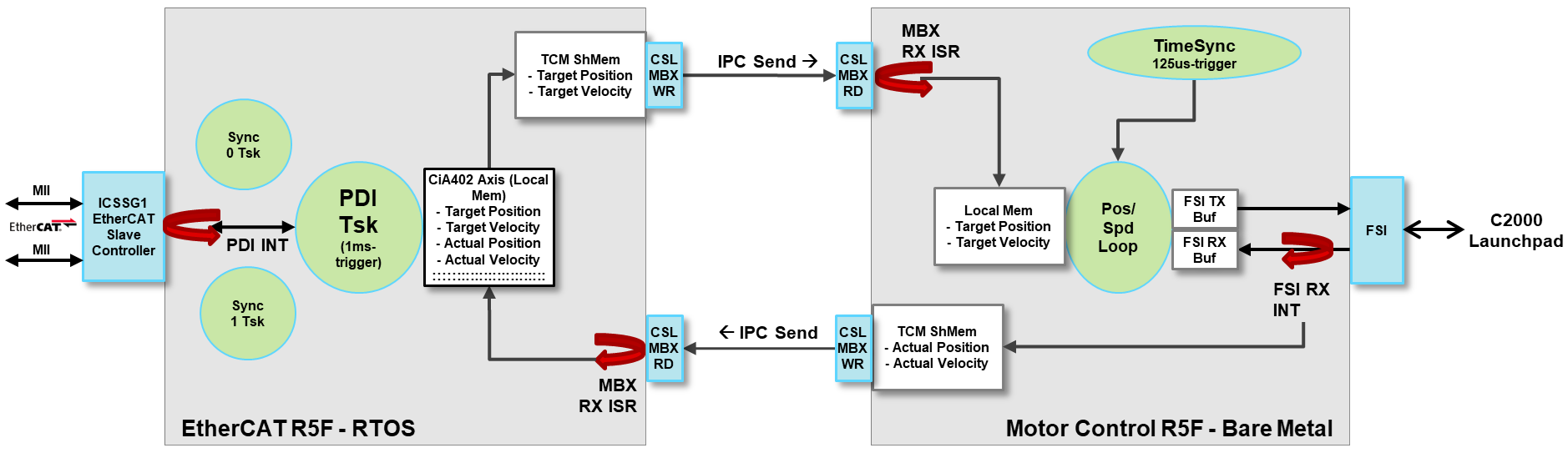
5.2.9.5. Real-Time Path Data Flow
The data flow diagram of the Servo Drive Demo is shown below and is made up of the following:
- ICSSG1 performing the EtherCAT slave controller function which creates three tasks for the EtherCAT R5F: SYNC0 task, SYNC1 task and the PDI task
- The PDI task occurs periodically as data arrives from the EtherCAT master.
This data arrival generates an interrupt on the EtherCAT R5F which runs the
CiA402 application state machine
- During operational runtime (OP state) the CiA402 application receives the latest ‘Target Position’ and ‘Target Velocity’ values from the EtherCAT master as well as transmits the latest ‘Actual Position’ and ‘Actual Velocity’ back to the EtherCAT master
- In addition to communicating with the EtherCAT master, the CiA402 application also uses the CSL Mailbox API to transfer the latest target values to the Motor Control R5F using its local TCM as a shared memory
- An interrupt occurs on the Motor Control R5F when new data is available from
the EtherCAT R5F core
- The newly received position and velocity targets are stored into local TCM memory to be used in the next position/speed loop algorithm cycle
- A TimeSync trigger occurs every 125us on the Motor Control R5F that is
synchronized to the EtherCAT SYNC0 pulse
- This trigger uses the mechanism described in the Demo Synchronization Technique
- The SYNC0 pulse occurs once every millisecond and the Motor Control R5F TimeSync trigger is a synchronized multiple of that event (8x in this case)
- The TimeSync trigger creates an interrupt that triggers the Position/Speed
loop algorithm to run using the latest Position/Speed targets received from
the EtherCAT master as well as the latest feedback data received from the
C2000 devices
- At the end of the Position/Speed loop algorithm, new target Flux and Torque values are created
- These newly created Flux and Torque reference values are then sent to the C2000 devices through an FSI TX peripheral
- Periodically the C2000 devices pass new feedback information back to the
Motor Control R5F. The Receive event creates an interrupt on the R5F
- The feedback data is stored locally in the R5F in order to be used in the next iteration of the Position/Speed loops
- The feedback data, mainly Actual Position and Actual Speed, is also sent to the EtherCAT R5F using the CSL Mailbox APIs
- This Mailbox receive interrupt on the EtherCAT R5F completes the full feedback loop as the Actual Position and Actual Speed are stored locally to be ready for the next PDI event to have the values sent back to the EtherCAT Master
5.2.10. Directory Contents
| Directory Name | Description | |
|---|---|---|
| 1 | apps/servo_drive_demo/c2000_slave/ | Contains a README, C2000 binary for the F28004x device, as well as modified files to rebuild from source |
| 2 | apps/servo_drive_demo/common/config/ | MEMORY section of the linker command file for the servo_drive_demo |
| 3 | apps/servo_drive_demo/include/ | Common structures and definitions shared between the position_speed_loop and ethercat_loop applications |
| 4 | apps/servo_drive_demo/libs/ | Libraries provided for the servo_drive_demo applications:
|
| 5 | apps/servo_drive_demo/ethercat_loop/ | TI RTOS based R5F EtherCAT slave stack application implementing the CiA402 interface and passing data to the other R5F over Mailbox IPC |
| 6 | apps/servo_drive_demo/out/ | Directory storing the output binaries after building the applications |
| 7 | apps/servo_drive_demo/ethercat_loop/emulation/ | Application written to emulate the data generated by the EtherCAT slave stack. Useful for testing the IPC between cores without the complication of the full EtherCAT stack or EtherCAT master. |
| 8 | apps/servo_drive_demo/position_speed_loop/ | Baremetal based R5F application performing the position speed loop and passing references values to the C2000 over FSI |
| 9 | apps/servo_drive_demo/position_speed_loop/emulation/ | Application written to emulate the data transfer between the position_speed_loop R5F and the ethercat_loop R5F. A loopback is performed on the data received. |
| 10 | apps/servo_drive_demo/safety_app/ | Baremetal based M4F application to showcase reset isolation and black channel communication with the Main Domain. |