4.4. RSTP
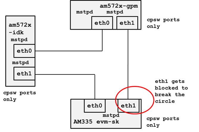
This is a simple demonstration example to setup a RSTP network which is a mode of the mstpd daemon that is provided in the Processors Linux SDK file system. This example setup is done from the Linux command line. Users that require automatic interface, bridge and msptd daemon setup at system initialization will need to do the steps necessary to implement this initialization method.
https://wiki.linuxfoundation.org/networking/bridge

3 node ring demonstrating port blocking on low cost link
Please note that the topology was tested across CPSW only ports, PRU-ICSS Ethernet only ports and a one CPSW and one PRU-ICSS port.
Setup the ports, IP addresses are not used for the Ethernet ports in a bridge.
ifconfig eth1 up
brctl addif br0 eth0
brctl addif br0 eth1
ifconfig br0 up
4.4.1. RSTP with ICSS Switch Firmware
With ICSS switch firmware, RSTP can be supported with L2 forwarding offload on the ICSSs in AM57x IDK platforms.
Briefly, in this case, the PRU ethernet driver together with the switch firmware are responsible for creating a forwarding database (FDB) table. MAC address in a frame received on a physical port is learned dynamically and a corresponding entry is created in the FDB table. When frames with a learned MAC address as the destination address is received, it will be cut-through forwarded to the port indicated in the FDB entry directly without involving the host.
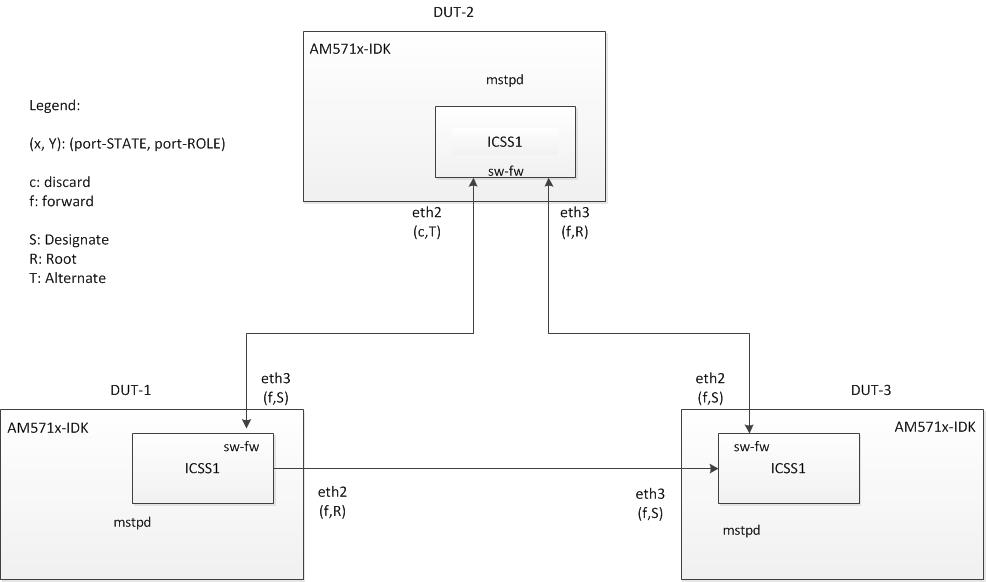
To set up a RSTP network with ICSS switch firmware, connect 3 AM571x-IDK as follows:

Boot up the IDKs as follows:
- Boot into uboot prompt.
- Modify args_mmc as follows:
=> setenv args_mmc ‘run finduuid;setenv bootargs console=${console} ${optargs} root=PARTUUID=${uuid} rw rootfstype=${mmcrootfstype} ti_prueth.pruss1_ethtype=3 ti_prueth.pruss2_ethtype=3’
=> saveenv
- Boot IDKs into linux prompt.
- Make sure the following lines appear in the boot log:
[   30.617491] prueth pruss1_eth: TI PRU ethernet (type 3) driver initialized
[   31.207474] prueth pruss2_eth: TI PRU ethernet (type 3) driver initialized
Note: timing is for reference only.
- Run the following script rstp.sh on each IDK.
#!/bin/bash
# rstp.sh

echo "mstpd"
mstpd
sleep 1

echo "ifconfig eth2 up"
ifconfig eth2 up
sleep 1

echo "ifconfig eth3 up"
ifconfig eth3 up
sleep 1

echo "brctl addbr br0"
brctl addbr br0
sleep 1

echo "brctl addif br0 eth2"
brctl addif br0 eth2
sleep 1
echo "brctl addif br0 eth3"
brctl addif br0 eth3
sleep 1

echo "brctl stp br0 on"
brctl stp br0 on
sleep 1

echo "mstpctl setforcevers br0 rstp"
mstpctl setforcevers br0 rstp
sleep 1

echo "ifconfig br0 up"
ifconfig br0 up
sleep 1

echo "mstpctl showbridge"
mstpctl showbridge
The script
- starts mstpd daemon
- crates a bridge interface br0 on eth2 and eth3
- enables rstp on the bridge br0
- shows some information about the bridge
- Issue command to show port information on each IDK:
$ mstpctl showport br0 eth2
$ mstpctl showport br0 eth3
sample output:
eth2 8.001 forw 8.000.70:FF:76:1C:16:EF 8.000.70:FF:76:1C:16:EF 8.001 Desg
where
forw is the port state
Desg is the port role
Note 1: In the test setup shown above , the port state and port role are shown in (state, role), eg. (f,R) - port state is forwarding and port role is Root.
Note 2: The (state, role) pairs may show on different DUTs but there must be a discard state appears. This discard state is a result of the RSTP protocol which breaks the cyclic connection into a tree (in this case, a serial connection.
In step 6, make sure the cyclic connection is broken by a discard state in one of the ports of one of the DUTs.
In setup in step 1, it is Dut2.eth2.
configure an IP address on br0 on any one DUT and another IP address of the same subnet on another DUT. E.g.
on Dut1: $ ifconfig br0 192.168.2.72
on Dut3: $ ifconfig br0 192.168.2.71
Make sure ping works fron Dut1 to Dut3.
Unplug any of the 3 cables and make sure the ping continues to work each time.
