6.3.4. 66AK2GX GP EVM Hardware Setup
Description
The EVMK2G is a high performance, cost-efficient, standalone development platform that enables users to evaluate and develop applications for the Texas Instrument’s Keystone2 System-on-Chip (SoC) 66AK2GX. The Key features of EVM are:
Processor and controller
- K2G SoC 66AK2GX is based on keystone II architecture with ARM cortex A15 @600MHz and C66x DSP @600MHz
- Board Management Controller (BMC) for board management functions like system status and Boot mode control
Volatile and non volatile Memory/Interfaces:
- 2GByte of DDR3L with ECC
- 2Gbit of NAND Flash
- 128Mbit of SPI Flash
- 512Mbit of QSPI Flash
- 128kByte of I2C EEPROM for Boot support from I2C
- Micro SD-Card slot
- 16GByte of eMMC
High speed and Serial Interfaces
- Gigabit Ethernet port supporting 10/100/1000 Mbps data rate on RJ45 connector
- PCIe x1 card slot
- COM8 interface
- DCAN and MLB interfaces
- One USB2.0 host and one USB2.0 Dual-role ports
- One RS232 serial interface on DB9 connector or UART over mini-USB connector, One UART interface on 6 pin header
Multimedia and display:
- 4.3” LCD display with Capacitive touch (Sold separately)
- HDMI transmitter
- Audio Line In and Line Out
JTAG and Emulation:
- MIPI 60-Pin JTAG header to support all types of external emulator
- On Board XDS200 Emulator
- Powered by DC power-wall adaptor (12V/5A)
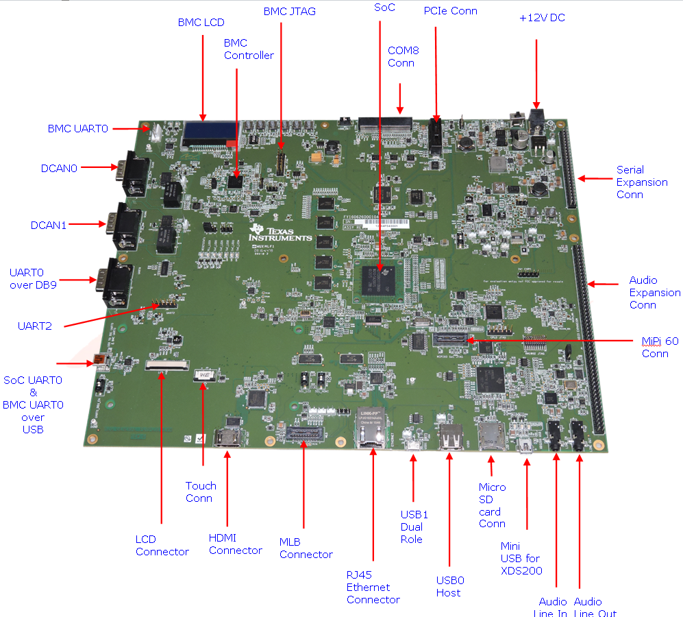
EVM Layout and Key Components
JTAG debug probes (aka Emulators) supported
List of standalone JTAG debug probes supported:
- XDS100-class JTAG debug probes (low cost, low performance). XDS100v1 is not supported.
- XDS200-class JTAG debug probes (recommended)
- XDS560v2-class JTAG debug probes (high performance)
Minimal EVM setup
Setting boot switches
The DIP Switch /Boot mode switch (SW3) is used for selecting the boot mode.
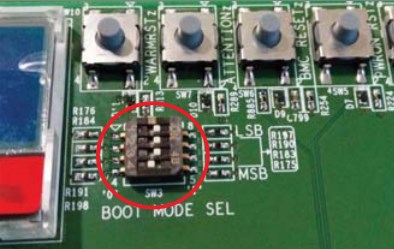
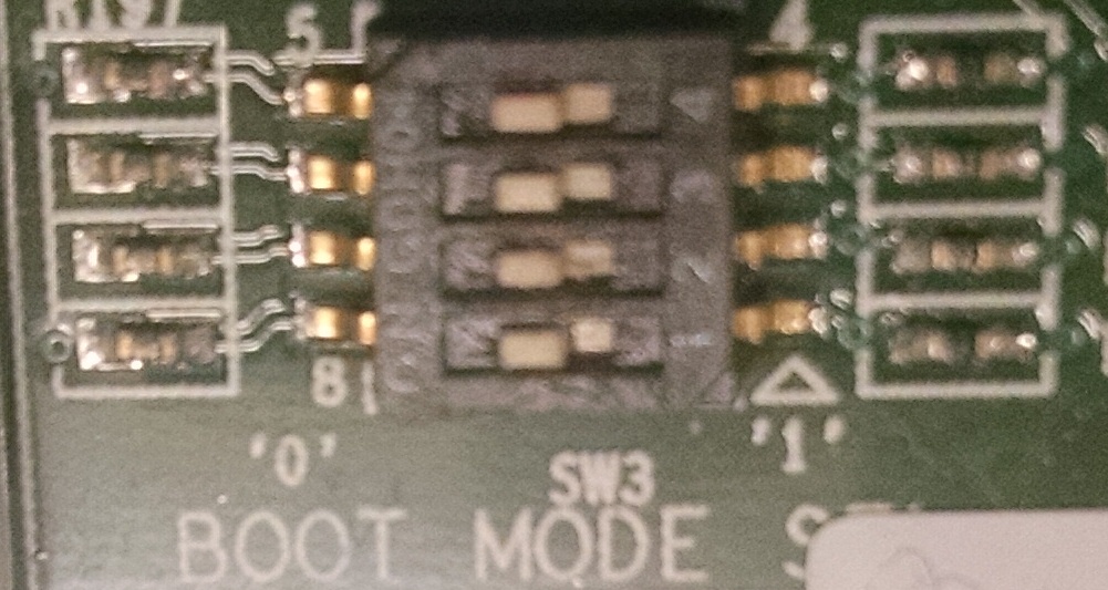
Note: Read the PCB marking around the boot switch for your EVM to interpret of ON and OFF marking on the switch
- For Rev C K2G02 GP EVM: ON = ‘0’ and OFF = ‘1’
- For Rev C/Rev D K2G12 GP EVM: ON = ‘1’ and OFF = ‘0’
Other Boot Pin configurations:
| SW3[4:1] | BOOT MODE |
|---|---|
| 0000 (0x0) | Sleep/No Boot |
| 0001 (0x1) | PCIe boot |
| 0010 (0x2) | Ethernet Boot |
| 0011 (0x3) | I2C PLL Boot |
| 0100 (0x4) | SPI No PLL Boot |
| 0101 (0x5) | SPI PLL-1 Boot |
| 0110 (0x6) | USB Boot |
| 0111 (0x7) | MMC/SD Boot |
| 1000 (0x8) | UART Boot |
| 1001 (0x9) | QSPI 96 Boot |
| 1010 (0xa) | eMMC Boot |
| 1011 (0xb) | NAND Boot |
| 1100 (0xc) | I2C No PLL Boot |
| 1101 (0xd) | SPI PLL-2 Boot |
| 1110 (0xe) | SPI PLL-3 Boot |
| 1111 (0xf) | QSPI 48 Boot |
Connecting Emulator
Note: This EVM setup is only required for developers who need to connect to cores using Code Composer studio to load application.
When external emulator is not connected to MIPI 60-pin connector, On-board XDS200 embedded JTAG emulator is the default type of emulation (SoC JTAG signals are routed to XDS200 on-board emulator). When external emulator is connected to MIPI 60-pin header, it is automatically detected and SoC JTAG signals are routed to external emulator.
On Board XDS200 emulator
EVMK2G has on-board XDS200 embedded JTAG emulation circuitry. Hence user does not require any external emulator to connect EVM with Code Composer Studio (CCS). User can connect target SoC in EVM to CCS through USB cable supplied in the EVM kit.
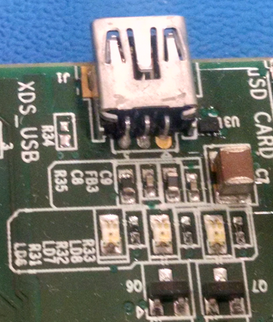
Use the USB to USB mini-B cable provided. Connect the USB mini-B connector to the USB mini-B interface near to the audio line in on the EVM, and the USB connector to your PC. This enables XDS-2xx emulation and is directly useable by CCS.
NOTE On Rev C boards and earlier revisions of the board, users who plan to connect the USB cable to USB 3.0 cable need to follow the instructions to update Emulation firmware using steps described in the article Updating_the_XDS200_firmware Without the firmware update, users are recommended to disconnect the mini USB cable from the XDS USB connector before powering up the EVM and reconnect after board power up is complete.
If you are using a different JTAG, you can connect it at MIPI60 connector (EMU1). The MIPI 60-pin JTAG header is provided on-board for high speed real-time emulation. All JTAG and EMUxx signals are terminated on MIPI 60-pin header.
No emulation firmware upgrade is required if users plan to use an external emulator The MIPI 60-pin JTAG header supports all standard (XDS510 or XDS560) TI DSP emulators. Please refer to the documentation supplied with your emulator for connection assistance.
Powering up the EVM
Power Supply specifications
The EVMK2G can be powered from a single +12V / 5.0A DC (60W) external power supply connected to the DC power jack (J3). Internally, +12V input is converted into required voltage levels using local DC-DC converters
Please note that a power supply is included with the 66AK2GX Evaluation Module. The power supply has the following specs :
- 12V DC output
- 5A output
- Positive inner and negative outer terminals
- Female barrel with 2.5mm inner diameter and 5.5mm outer diameter
- Isolated power supply
CCS Setup
This section describes the setup to connect to 66AK2GX GP EVM using Code composer Studio environment and an emulator.
There are two scenarios while connecting to the EVM :
- Connect to EVM without a SD card boot image to boot the EVM
- Connect to EVM after booting an image from the SD card.
Before discussing both these scenarios, let us look at how to pull in the latest KeystoneII device support in CCSv6
Update CCS v6 to install Keystone II device Support package
All revisions of the board require this step to be performed in order to get the latest GEL files and the target content for the K2G. This step will not be required for CCS versions higher than version 6.1.3. CCSv6.1.3 package contain KeystoneII device support package v1.1.4 which doesn`t contain 66AK2GX GPEVM specific target files hence we recommend this update.
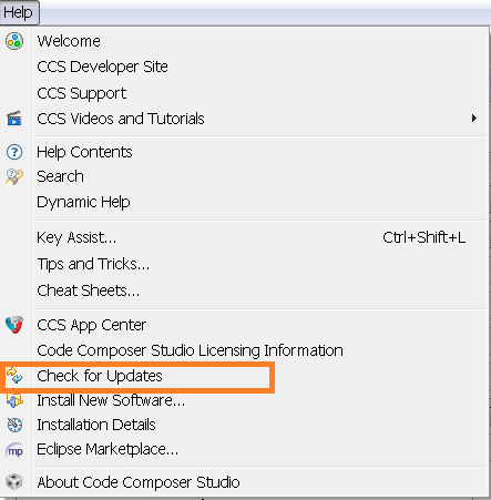
Step 1 All CCS v6.1.3 and earlier version users are required to update the Keystone Device Support package by going into the Help->Check For Updates
Step 2 Select Keystone2 device support package. Follow menu options to continue with the update
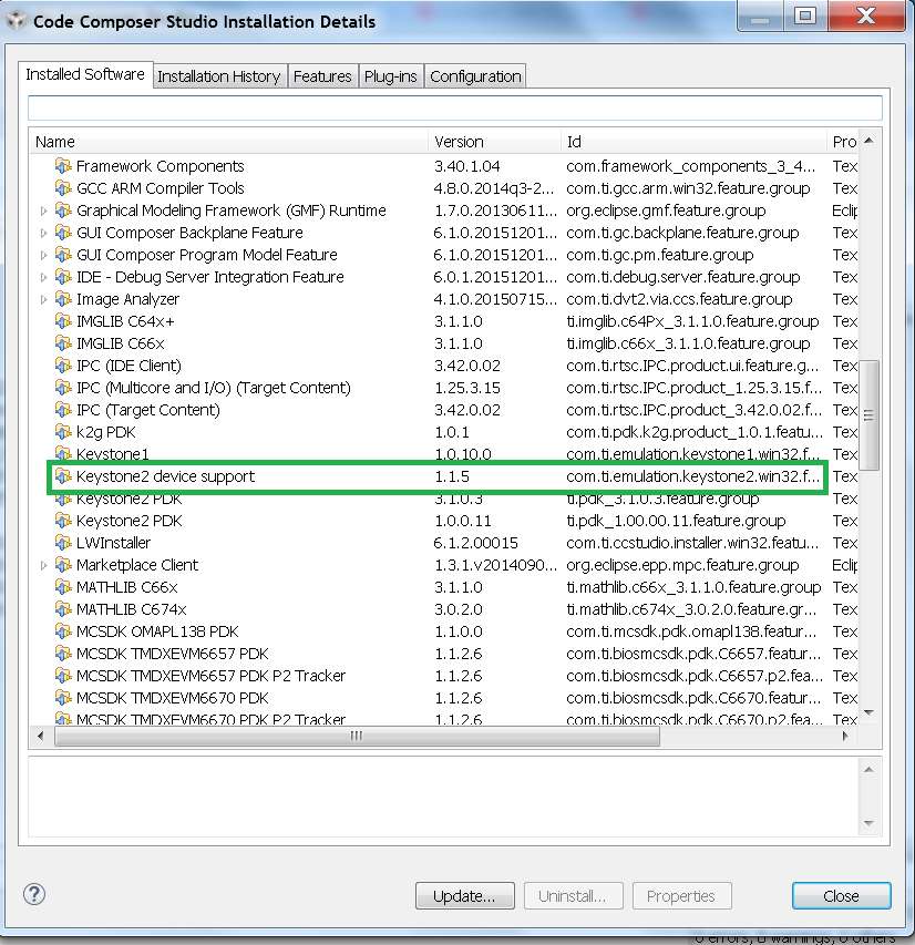
Step 3 After the update is complete go to Help->Installation details and check that Keystone2 device support package v1.1.5 or later are installed as shown below
Note: The package can be downloaded separately from the link below and manually unzipped into CCSv6 installation.
Connect without a SD card boot image
Configuring target configuration files
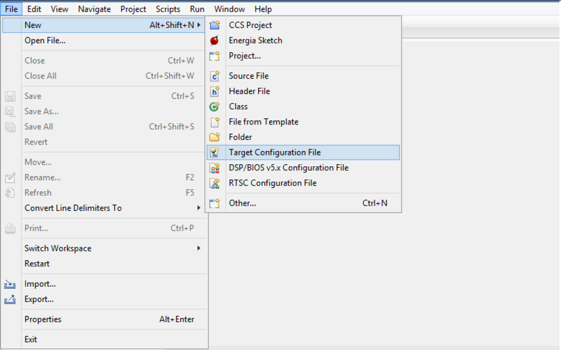
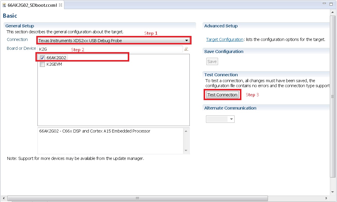
Launch CCS and create new target configuration(File->New->Target Configuration file) as shown in the images below
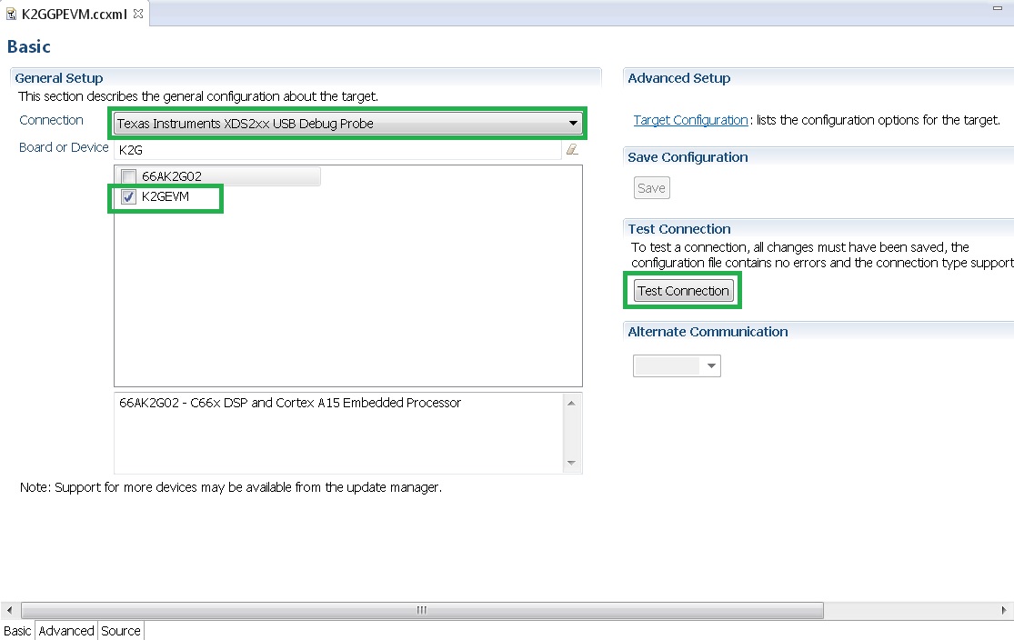
Provide appropriate name to the configuration. Select Spectrum digital XDS200 emulator and target as K2G GPEVM.
Note: If you don`t find the 66AK2G02 target make sure you have installed the CCSv6.1.3 package or for CCSv6.1.2 and earlier ensure that you have done the software update correctly as shown in the how to section below.
In advance settings, make sure that the gel files are populated correctly. The following GEL files and their corresponding cores are provided below:
- C66X Core: evmk2g.gel
- A15 Core: evmk2g_arm.gel
Connecting to target
Step1 : Download Code composer Studio v6.1.3 or for CCSv6.1.2 and earlier, ensure it contains Keystone device support package version 1.1.5 as described in the how to guide
Install Code composer Studio v6 for K2G
- Step2: 66AK2GX GP EVM contains boot switches to configure for “No
- boot/sleep” mode. So configure the boot switches to No Boot Mode as described in the SettingBootSwitches
Step3: Connect an XDS200 Emulator to XDS USB of the GP EVM as shown in ConnectingEmulator
Step4: Launch CCS and create new target configuration as discussed in the previous section ConfiguringTargetConfigFile
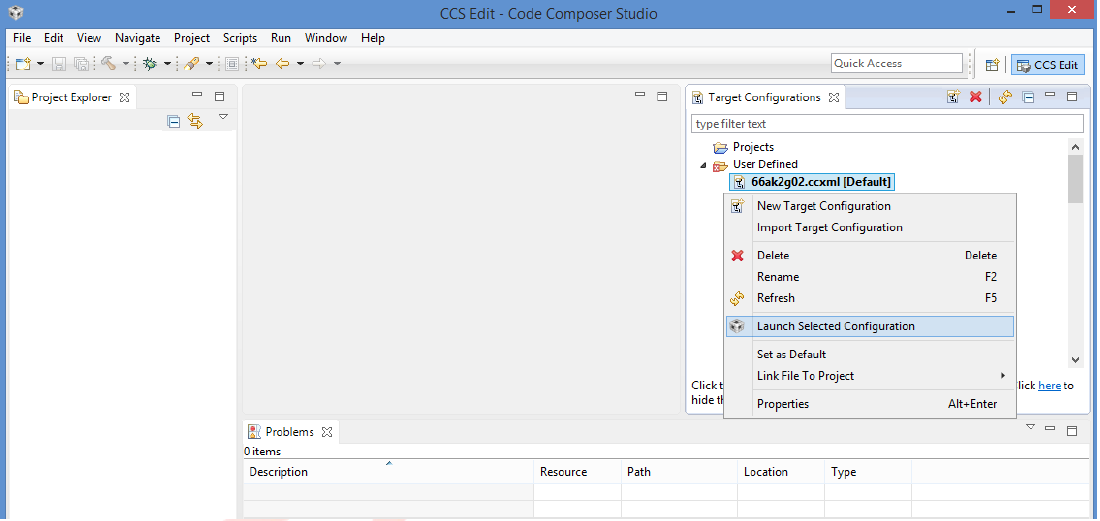
Step5: Launch Target configuration you just created.
- Step6:K2G can be a DSP or an ARM master boot device so connect to
- the C66x or the A15_0.
GEL Log
A15_0: GEL Output: PLL has been configured (24.0 MHz * 100 / 1 / 4 = 600.0 MHz)
A15_0: GEL Output: ARM PLL has been configured with ref clock 24MHz, -sysclkp_period 41.6666 (24.0 MHz * 100 / 1 / 4 = 600.0 MHz)
A15_0: GEL Output: Power on all PSC modules and DSP domains...
A15_0: GEL Output: Power on PCIE PSC modules and DSP domains... Done.
A15_0: GEL Output: UART PLL has been configured (24.0 MHz * 128 / 1 / 8 = 384.0 MHz)
A15_0: GEL Output: NSS PLL has been configured (24.0 MHz * 250 / 3 / 2 = 1000.0 MHz)
A15_0: GEL Output: ICSS PLL has been configured (24.0 MHz * 250 / 3 / 10 = 200.0 MHz)
A15_0: GEL Output: DSS PLL has been configured (24.0 MHz * 198 / 12 / 16 = 24.75 MHz)
A15_0: GEL Output: DDR PLL has been configured (24.0 MHz * 250 / 3 / 10 = 200.0 MHz)
A15_0: GEL Output: XMC setup complete. A15_0: GEL Output: DDR3 PLL Setup ...
A15_0: GEL Output: DDR3 PLL Setup complete, DDR3A clock now running at 400MHz.
A15_0: GEL Output: DDR3A initialization complete
Connect with a SD card boot image
Launch CCS and create new target configuration(File->New->Target Configuration file) as shown in the images below
Provide appropriate name to the configuration. Select Spectrum digital XDS200 emulator and target as 66AK2G02.
Note: If you don`t find the 66AK2G02 target make sure you have installed the CCSv6.1.3 package or for CCSv6.1.2 and earlier ensure that you have done the software update correctly as shown in the how to section below.
In advance settings, make sure that the no gel files are populated.
Step2: 66AK2G02 GP EVM contains boot switches to configure for “SD/MMC boot” mode. So configure the boot switches to SD/MMC boot Mode as described in the SettingBootSwitches
Step3: Connect an XDS200 Emulator to XDS USB of the GP EVM as shown in section ConnectingEmulator
Step4: Launch CCS and create new target configuration as discussed in the previous section ConfiguringTargetConfigFile
Step5: Launch Target configuration you just created.
Step6:K2G will boot with ARM master boot from the SD card so connect to the A15_0. There will be no output on the console when you connect to the core.
Step7 SD card boot image will typically load a secondary bootloader like u-boot that will put the DSP in reset so user will need to follow the instructions on the page that talks about Taking DSP out of reset
Note: RTOS users don`t need to follow this step as the Secondary bootloader (SBL) will put the DSP in idle state and not in reset if there is no code running on the DSP.
How to guide
This section guides users who are using older versions of the GP EVM which may require an update to the firmware flashed on the EVM or hardware updates to workaround specific issues. Each section specifies the affected versions and the fix for the issue.
Create SD card to boot Linux on the GP EVM
All pre-production boards (Rev C and earlier) will not contain a SD card image in the kit without an image flashed on it for the Out of Box experience described in the Quick start guide. User are required to download the image seperately from the Processor SDK Linux portal and run a script to create the SD boot image. The steps to create the image are provided below:
Step 1 Download the image k2g-evm-linux-xx.xx.xx.xx.img.zip from the link Latest Processor SDK Linux
Step 2 Follow instructions to create a SD card for the EVM using the instruction in the SD Card Creation Guide
Update the BMC firmware on the EVM
The section describes how the Board Management controller firmware on the board can be updated through the BMC UART interface. All boards prior to RevC, require a BMC update for the following issue:
- CDCM chip on the board generates clocks to modules like PCIe and USB. It is possible to use PCIe only in external clock mode on the EVM. However there can be use-cases where PCIe clock should be enabled with SoC running in internal clock mode.
Step 1 Install the LM flash programmer from link provided below:
Step 2 Obtain latest BMC software for the K2G GP EVM can be obtained from the board manufacturer or from local TI contact. Production EVMs are shipped with latest BMC version 0.6.1.0. You can check the version of the BMC software by observing the version indicated on BMC LCD on the GP EVM after power up.
Step 3 Connect the mini USB cable between host PC and ‘USB to SoC UART0’ port (J23) on EVM
Step 4 Remove the jumper J10 and power on the K2G EVM
Step 5 Open the LM Flash programmer utility on the windows host machine.
Step 6 In the LM Flash Programmer Utility ‘Configuration’ tab, in the interface section, select ‘Serial (UART)’ from the drop-down box on the left.Refer to the image provided below:
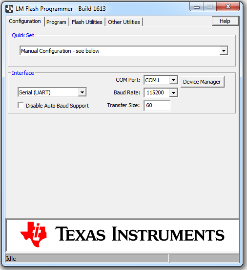
Step 7 Select the BMC COM Port and set the ‘Baud Rate’ to 115200.
- There will be two COM ports that appears on EVMs ‘USB to SoC UART0’ port. Select the one which is connected to BMC. To find which port corresponds to the BMC, you can open a serial terminal program or Device Manager on your PC and check the port number corresponding to “Silicon Labs CP210x: USB to UART Bridge: Standard COM Port (COM##)” as shown below:
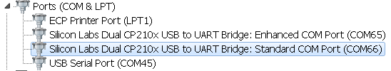
Note: BMC outputs boot logs to serial console when EVM is powered ON. Connect the ‘USB to SoC UART0’ port to standard serial console application to find the right COM port that is connected to BMC.
Step 8 Set ‘Transfer Size’ to 60, and make sure ‘Disable Auto Baud Support’ is unchecked.
Step 9 In the ‘Program’ tab, select the binary image file bmc_evmKS2_K2G.bin in the section ‘Select.bin file’.
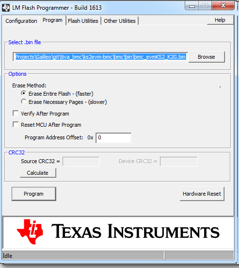
Step 10 Leave all other options as default, and press the ‘Program’ button.
Step 11 Wait till ‘Program Complete’ status in the status bar.
Step 12 Connect the jumper J10 and reboot the EVM
Update XDS200 firmware and hardware components on the GP EVM
Note: This update is only required if you are using the on board XDS200 debug probe.
The RevB and RevC boards are using an earlier version of the XDS200 firmware. We have observed the following issues when hooking up the internal XDS200 USB debug probe to a host machine.
- XDS200 Emulator USB cable need to be re-plugged every time board is power cycled/reset to avoid leakage on power supply VCC1V8_XDS which can damage the regulator or other ICs
Workaround for this issue
- Use external emulators with the MIPI 60 adapter included int he kit.
- Perform following firmware and hardware updates to the GP EVM (RevC and earlier)
Software Update Required
Steps to update the XDS200 firmware on the EVM are archived on the article Updating_the_XDS200_firmware
Hardware updates required
- Replace R431 & R442 to 200E
- Mount resistors R95, R107, R108, R115.
- Mount D2, R600, R599 components.
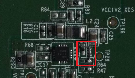
- Remove FB3 and connect a wire from R64.2 ‘rVCC_VBUS_XDS’ and R67.2 ‘VCC5V0_DCDC’ as shown in the image below:
Update the EVM for improved USB performance
The external resistors for the USB (R442 and R431) are currently 10k Ω. We recommend that users need to replace these with 200 Ω / 1%.
Useful Resources and Support