3.2.2.2. CSI2RX
3.2.2.2.1. Introduction
The CSI2RX subsystem is present on some TI SoCs which facilitates the capture of camera frames over a MIPI CSI-2 bus. The driver is based on the Video for Linux 2 (V4L2) API. It implements V4L2’s Media Controller (MC) API.
3.2.2.2.2. Hardware Architecture
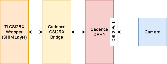
The CSI2RX subsystem is composed of 3 IPs: Cadence DPHY, Cadence CSI2RX bridge, TI CSI2RX DMA wrapper (aka the SHIM layer).
The CSI2RX subsystem supports the following features:
- Compliant to MIPI CSI v1.3
- Supports up to 16 virtual channels per input (partial MIPI CSI v2.0 feature).
- Data rate up to 2.5 Gbps per lane (wire rate).
- Supports 1, 2, 3, or 4 data lane connection to DPHY_RX.
- Programmable formats including YUV420, YUV422, RGB, Raw, etc.
See the the technical reference manual (TRM) for the SoC in question for more detailed information.
3.2.2.2.3. Driver Architecture
The driver is based on the Video 4 Linux 2 (V4L2) API. It is implemented according to the V4L2 standard for capture devices. The driver is only responsible for programming the SoC components for capture like the DPHY, CSI bridge, DMA. For external devices like camera sensors separate V4L2 subdevice drivers are needed.
3.2.2.2.3.1. The Media Controller API
The driver is implemented using V4L2’s Media Controller (MC) API. In the MC API, each element in the media pipeline is configured individually by the user-space application. In comparison, in the legacy or non-MC API drivers, only the /dev/videoX node needs to be configured, and it propagates the configuration up the chain. With this model, the MC API allows for more flexible pipeline configurations which can all be controlled from user-space without having to change the driver or the device tree.
For example, with the legacy API the format is set on /dev/videoX and that will set it for the entire pipeline (sensor, bridge, DMA engine, etc). With the MC API, the format needs to be set on each individual element in the pipeline. So with a single camera setup, for capturing 1920x1080 @ 60fps UYVY, the camera (/dev/v4l-subdevX) should first be configured to use that format via the V4L2 subdev ioctls. Then the /dev/videoX node (which represents the DMA context) should be configured to use matching configuration. The Media Controller framework checks for mismatches and reports errors if something is not right.
In similar fashion, the DMA context does not care about frame rate. It can capture at any rate, so the driver does not implement the G_PARM or S_PARM ioctls. Instead, the frame rate should be set on the sensor using VIDIOC_SUBDEV_S_FRAME_INTERVAL.
Quick links for relevant Linux Kernel documentation:
3.2.2.2.3.2. Utilities to interact with the driver
Standard V4L2 utilities can be used to set these formats and frame rates. One such tool is media-ctl.
To see the media pipeline to understand how all the components are connected in software, the pipeline can be printed to the console using “media-ctl -p”. This would list all the elements in the pipeline, what they are connected to, and their names. This information can then be used to set formats and frame rates on various elements for the pipeline. For example, below command can be used to set 1920x1080 @ 30fps UYVY format on the sensor node:
media-ctl --set-v4l2 '"sensor-name 9-0012":0 [fmt:UYVY8_2X8/1920x1080@1/30]'
This just sets the formats on the sensor and bridge. The format on the DMA context (/dev/videoX) needs to be set separately. This can be done while starting the capture with yavta for example. The below command can be run next to start capturing the video stream to a file called “capture”:
yavta -c -Fcapture -s 1920x1080 -f UYVY /dev/video0
This command first sets the 1920x1080 UYVY format on the DMA context (which must match the format on the sensor), and then starts capturing frames to a file called “capture”.
It is often useful to see the pipeline visually. media-ctl can print the pipeline as a dot graph which can then be converted to an image for viewing. The below set of commands can achieve this:
media-ctl --print-dot | dot -Tpng > graph.png
3.2.2.2.3.3. Building the driver
First, enable the DPHY using CONFIG_PHY_CADENCE_DPHY. Then enable the CSI2RX bridge using CONFIG_VIDEO_CADENCE and CONFIG_VIDEO_CADENCE_CSI2RX. Finally, enable CONFIG_VIDEO_TI_J721E_CSI2RX. The config for the sensor should also be enabled.
The driver can be built-in or it can be a loadable module. If the driver is built as a module, the module will be called j721e-csi2rx. Along with that, the Cadence bridge and DPHY modules must also be loaded, which are called cdns-csi2rx and cdns-dphy respectively.
3.2.2.2.4. Creating device tree nodes for sensor
Since the sensor is a separate module and any sensor can be plugged in to the board, the sensor device tree nodes are not included in the base dtb. Instead, it should be added in as an overlay.
Below overlay is an example for adding the overlay nodes:
// SPDX-License-Identifier: GPL-2.0
/*
 * Copyright (C) 2021 Texas Instruments Incorporated - https://www.ti.com/
 */

/dts-v1/;
/plugin/;

#include <dt-bindings/gpio/gpio.h>

&main_i2c6 {
    #address-cells = <1>;
    #size-cells = <0>;

    camera_sensor: camera@12 {
            compatible = "manufacturer,sensor-compatible";
            reg = <0x12>;

                    /* Other sensor properties go here... */

            port {
                    csi2_cam0: endpoint {
                            remote-endpoint = <&csi2rx0_in_sensor>;
                            clock-lanes = <0>;
                            /*
                             * This example sensor uses 2 lanes. Other sensors might use
                             * 1, 2, 3, or 4 lanes. Populate this property accordingly.
                             * See Documentation/devicetree/bindings/media/video-interfaces.yaml
                             * for more info.
                             */
                            data-lanes = <1 2>;
                    };
            };
    };
};

&csi0_port0 {
    status = "okay";

    csi2rx0_in_sensor: endpoint {
            remote-endpoint = <&csi2_cam0>;
            bus-type = <4>; /* CSI2 DPHY. */
            clock-lanes = <0>;
            data-lanes = <1 2>;
    };
};
3.2.2.2.5. Enabling camera sensors
SK-AM62 supports the following 15-pin FFC compatible camera modules with OV5640 sensor:
- TEVI-OV5640-*-RPI
- Digilent PCam5C
- ALINX AN5641
They can be tested with the following steps:
3.2.2.2. Applying sensor overlays
During bootup stop at u-boot prompt by pressing any key and enable camera devicetree overlay:
# For Digilent PCam5C or ALINX AN5641
setenv name_overlays ti/k3-am625-sk-csi2-ov5640.dtbo
boot

# For Technexion TEVI-OV5640
setenv name_overlays ti/k3-am625-sk-csi2-tevi-ov5640.dtbo
boot
Once the overlay is applied, you can confirm that the sensor is being probed by checking the output of lsmod or the media graph:
$ lsmod | grep ov5640
ov5640                 36864  1
v4l2_fwnode            20480  2 ov5640,cdns_csi2rx

$ media-ctl -p
Media controller API version 6.1.33
Media device information
------------------------
driver          j721e-csi2rx
model           TI-CSI2RX
serial
bus info        platform:30102000.ticsi2rx
hw revision     0x1
driver version  6.1.33

Device topology
....
- entity 13: ov5640 4-003c (1 pad, 1 link, 0 route)
             type V4L2 subdev subtype Sensor flags 0
             device node name /dev/v4l-subdev2
        pad0: Source
                [stream:0 fmt:UYVY8_1X16/640x480@1/30 field:none colorspace:srgb xfer:srgb ycbcr:601 quantization:full-range
                 crop.bounds:(0,0)/2624x1964
                 crop:(16,14)/2592x1944]
                -> "cdns_csi2rx.30101000.csi-bridge":0 [ENABLED,IMMUTABLE]
....
3.2.2.2. Capturing raw frames
Once the media pipeline is configured, you should be able to capture raw frames from the sensor using any tool compliant with v4l2 apis. For example you can use libcamera to capture 20 frames @ 480p:
$ cam -c1 --stream width=640,height=480,pixelformat=UYVY -C20
You can also capture at other sensor-supported resolutions:
# List supported resolutions
$ cam -c1 -I
# Capture 20 frames @ 1024x768
$ cam -c1 --stream width=1024,height=768,pixelformat=UYVY -C20
Note: Due to a bug in the driver only UYVY format works with libcamera tool. You can still manually change the format using media-ctl to use with other tools.
To save the raw YUV frames to SD card for viewing later use the -F option:
$ cam -c1 --stream width=640,height=480,pixelformat=UYVY -C20 -F#.uyvy
$ ls *.uyvy
-rw-r--r-- 1 root root 614400 Jan  1 19:19 cam0-stream0-000000.uyvy
-rw-r--r-- 1 root root 614400 Jan  1 19:19 cam0-stream0-000001.uyvy
-rw-r--r-- 1 root root 614400 Jan  1 19:19 cam0-stream0-000002.uyvy
-rw-r--r-- 1 root root 614400 Jan  1 19:19 cam0-stream0-000003.uyvy
-rw-r--r-- 1 root root 614400 Jan  1 19:19 cam0-stream0-000004.uyvy
Alternatively you can use tools like yavta or v4l2-ctl, but please note they require manual configuration using media-ctl if you want to stream at a different resolution and formats than the default (640x480 UYVY):
$ yavta -s 640x480 -f UYVY /dev/video0 -c20
....
$ v4l2-ctl -d0 --stream-mmap -v width=640,height=480,pixelformat=UYVY
3.2.2.2. Capture to display
If a display (HDMI or LVDS) is connected then use the following steps to view the camera frames:
# As a window within weston desktop
$ gst-launch-1.0 v4l2src device="/dev/video0" ! video/x-raw, width=640, height=480, format=UYVY ! autovideosink

# Direct KMS Sink
$ systemctl stop weston
$ gst-launch-1.0 v4l2src device="/dev/video0" ! video/x-raw, width=640, height=480, format=UYVY ! queue ! kmssink driver-name=tidss
You can also replace v4l2src with libcamerasrc above if you want to test different sensor-supported resolutions like 480p, 720p etc.
$ gst-launch-1.0 libcamerasrc ! video/x-raw, width=1024, height=768, format=UYVY ! autovideosink
3.2.2.2. Suspend to RAM
The camera pipeline supports system supend to RAM on SK-AM62. You can refer to Power Management guide for more details.
For example, you can start streaming from camera using any of the above methods and then suspend to RAM for 5 seconds using the following command:
$ rtcwake -s 5 -m mem
The system will automatically wake-up after 5 seconds, and camera streaming should resume from where it left (as long as the sensor supports it).
The Technexion TEVI-OV5640 module supports this, but it may fail to set the sensor registers in time when built as a module. You can fix this by making it a part of the kernel image:
diff --git a/arch/arm64/configs/defconfig b/arch/arm64/configs/defconfig
index 1f402994efed..0f081e5f96c1 100644
--- a/arch/arm64/configs/defconfig
+++ b/arch/arm64/configs/defconfig
@@ -739,14 +739,14 @@ CONFIG_RC_DECODERS=y
 CONFIG_RC_DEVICES=y
 CONFIG_IR_MESON=m
 CONFIG_IR_SUNXI=m
-CONFIG_MEDIA_SUPPORT=m
+CONFIG_MEDIA_SUPPORT=y
 # CONFIG_DVB_NET is not set
 CONFIG_MEDIA_USB_SUPPORT=y
 CONFIG_USB_VIDEO_CLASS=m
 CONFIG_V4L_PLATFORM_DRIVERS=y
 CONFIG_SDR_PLATFORM_DRIVERS=y
 CONFIG_V4L_MEM2MEM_DRIVERS=y
-CONFIG_VIDEO_CADENCE_CSI2RX=m
+CONFIG_VIDEO_CADENCE_CSI2RX=y
 CONFIG_VIDEO_WAVE_VPU=m
 CONFIG_VIDEO_IMG_VXD_DEC=m
 CONFIG_VIDEO_IMG_VXE_ENC=m
@@ -764,12 +764,12 @@ CONFIG_VIDEO_SAMSUNG_EXYNOS_GSC=m
 CONFIG_VIDEO_SAMSUNG_S5P_JPEG=m
 CONFIG_VIDEO_SAMSUNG_S5P_MFC=m
 CONFIG_VIDEO_SUN6I_CSI=m
-CONFIG_VIDEO_TI_J721E_CSI2RX=m
+CONFIG_VIDEO_TI_J721E_CSI2RX=y
 CONFIG_VIDEO_HANTRO=m
 CONFIG_VIDEO_IMX219=m
 CONFIG_VIDEO_IMX390=m
 CONFIG_VIDEO_OV2312=m
-CONFIG_VIDEO_OV5640=m
+CONFIG_VIDEO_OV5640=y
 CONFIG_VIDEO_OV5645=m
 CONFIG_VIDEO_DS90UB953=m
 CONFIG_VIDEO_DS90UB960=m
@@ -1309,8 +1309,8 @@ CONFIG_PHY_XGENE=y
 CONFIG_PHY_CAN_TRANSCEIVER=m
 CONFIG_PHY_SUN4I_USB=y
 CONFIG_PHY_CADENCE_TORRENT=y
-CONFIG_PHY_CADENCE_DPHY=m
-CONFIG_PHY_CADENCE_DPHY_RX=m
+CONFIG_PHY_CADENCE_DPHY=y
+CONFIG_PHY_CADENCE_DPHY_RX=y
 CONFIG_PHY_CADENCE_SIERRA=y
 CONFIG_PHY_MIXEL_MIPI_DPHY=m
 CONFIG_PHY_FSL_IMX8M_PCIE=y
To re-build the kernel with above changes you can refer to the Users Guide.