3.2.2.2. CSI2RX
3.2.2.2.1. Introduction
The CSI2RX subsystem is present on some TI SoCs which facilitates the capture of camera frames over a MIPI CSI-2 bus. The driver is based on the Video for Linux 2 (V4L2) API. It implements V4L2’s Media Controller (MC) API.
3.2.2.2.2. Hardware Architecture
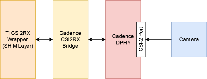
The CSI2RX subsystem is composed of 3 IPs: Cadence DPHY, Cadence CSI2RX bridge, TI CSI2RX DMA wrapper (aka the SHIM layer).
The CSI2RX subsystem supports the following features:
- Compliant to MIPI CSI v1.3
- Supports up to 16 virtual channels per input (partial MIPI CSI v2.0 feature).
- Data rate up to 2.5 Gbps per lane (wire rate).
- Supports 1, 2, 3, or 4 data lane connection to DPHY_RX.
- Programmable formats including YUV420, YUV422, RGB, Raw, etc.
See the the technical reference manual (TRM) for the SoC in question for more detailed information.
3.2.2.2.3. Driver Architecture
The driver is based on the Video 4 Linux 2 (V4L2) API. It is implemented according to the V4L2 standard for capture devices. The driver is only responsible for programming the SoC components for capture like the DPHY, CSI bridge, DMA. For external devices like camera sensors separate V4L2 subdevice drivers are needed.
3.2.2.2.3.1. The Media Controller API
The driver is implemented using V4L2’s Media Controller (MC) API. In the MC API, each element in the media pipeline is configured individually by the user-space application. In comparison, in the legacy or non-MC API drivers, only the /dev/videoX node needs to be configured, and it propagates the configuration up the chain. With this model, the MC API allows for more flexible pipeline configurations which can all be controlled from user-space without having to change the driver or the device tree.
For example, with the legacy API the format is set on /dev/videoX and that will set it for the entire pipeline (sensor, bridge, DMA engine, etc). With the MC API, the format needs to be set on each individual element in the pipeline. So with a single camera setup, for capturing 1920x1080 @ 60fps UYVY, the camera (/dev/v4l-subdevX) should first be configured to use that format via the V4L2 subdev ioctls. Then the /dev/videoX node (which represents the DMA context) should be configured to use matching configuration. The Media Controller framework checks for mismatches and reports errors if something is not right.
In similar fashion, the DMA context does not care about frame rate. It can capture at any rate, so the driver does not implement the G_PARM or S_PARM ioctls. Instead, the frame rate should be set on the sensor using VIDIOC_SUBDEV_S_FRAME_INTERVAL.
Quick links for relevant Linux Kernel documentation:
3.2.2.2.3.2. Utilities to interact with the driver
Standard V4L2 utilities can be used to set these formats and frame rates. One such tool is media-ctl.
To see the media pipeline to understand how all the components are connected in software, the pipeline can be printed to the console using “media-ctl -p”. This would list all the elements in the pipeline, what they are connected to, and their names. This information can then be used to set formats and frame rates on various elements for the pipeline. For example, below command can be used to set 1920x1080 @ 30fps UYVY format on the sensor node:
media-ctl --set-v4l2 '"sensor-name 9-0012":0 [fmt:UYVY8_2X8/1920x1080@1/30]'
This just sets the formats on the sensor and bridge. The format on the DMA context (/dev/videoX) needs to be set separately. This can be done while starting the capture with yavta for example. The below command can be run next to start capturing the video stream to a file called “capture”:
yavta -c -Fcapture -s 1920x1080 -f UYVY /dev/video0
This command first sets the 1920x1080 UYVY format on the DMA context (which must match the format on the sensor), and then starts capturing frames to a file called “capture”.
It is often useful to see the pipeline visually. media-ctl can print the pipeline as a dot graph which can then be converted to an image for viewing. The below set of commands can achieve this:
media-ctl --print-dot | dot -Tpng > graph.png
3.2.2.2.3.3. Building the driver
First, enable the DPHY using CONFIG_PHY_CADENCE_DPHY. Then enable the CSI2RX bridge using CONFIG_VIDEO_CADENCE and CONFIG_VIDEO_CADENCE_CSI2RX. Finally, enable CONFIG_VIDEO_TI_J721E_CSI2RX. The config for the sensor should also be enabled.
The driver can be built-in or it can be a loadable module. If the driver is built as a module, the module will be called j721e-csi2rx. Along with that, the Cadence bridge and DPHY modules must also be loaded, which are called cdns-csi2rx and cdns-dphy respectively.
3.2.2.2.4. Creating device tree nodes for sensor
Since the sensor is a separate module and any sensor can be plugged in to the board, the sensor device tree nodes are not included in the base dtb. Instead, it should be added in as an overlay.
Below overlay is an example for adding the overlay nodes:
// SPDX-License-Identifier: GPL-2.0
/*
 * Copyright (C) 2021 Texas Instruments Incorporated - https://www.ti.com/
 */

/dts-v1/;
/plugin/;

#include <dt-bindings/gpio/gpio.h>

&main_i2c6 {
    #address-cells = <1>;
    #size-cells = <0>;

    camera_sensor: camera@12 {
            compatible = "manufacturer,sensor-compatible";
            reg = <0x12>;

                    /* Other sensor properties go here... */

            port {
                    csi2_cam0: endpoint {
                            remote-endpoint = <&csi2rx0_in_sensor>;
                            clock-lanes = <0>;
                            /*
                             * This example sensor uses 2 lanes. Other sensors might use
                             * 1, 2, 3, or 4 lanes. Populate this property accordingly.
                             * See Documentation/devicetree/bindings/media/video-interfaces.yaml
                             * for more info.
                             */
                            data-lanes = <1 2>;
                    };
            };
    };
};

&csi0_port0 {
    status = "okay";

    csi2rx0_in_sensor: endpoint {
            remote-endpoint = <&csi2_cam0>;
            bus-type = <4>; /* CSI2 DPHY. */
            clock-lanes = <0>;
            data-lanes = <1 2>;
    };
};
3.2.2.2.5. Example camera pipeline
SK-AM62A supports the following FPDLink cameras using fusion board: IMX390, OV2312; and the following 22-pin FFC compatible cameras: IMX219.
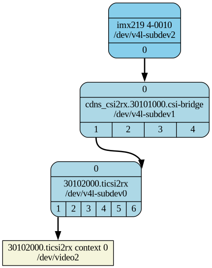
For sensors directly connected to the SK using the FFC connector, the media graph is fairly simple. For example IMX219 is connected to the CSI-RX bridge directly, which ultimately ends up at a /dev/videoX node:
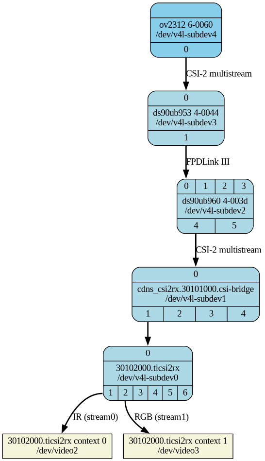
For sensors connected using FPDLink fusion board, the pipeline is a bit more complicated. For example OV2312 is a multi-stream sensor, which is first connected to a CSI-to-FPD serializer, and then to FPD-to-CSI deserializer, finally routing the two virtual channels (streams) to separate /dev/videoX nodes:
3.2.2.2. Applying sensor overlays
To enable FPDLink cameras you will need to apply the device tree overlays for both the fusion board and the sensor at U-boot prompt:
# For OV2312 connected on Fusion board RX Port 0:
setenv name_overlays k3-am62a7-fpdlink-sk-fusion.dtbo k3-am62a7-fpdlink-ov2312-0-0.dtbo
boot

# For RCM IMX390 connected on Fusion board RX Port 0:
setenv name_overlays k3-am62a7-fpdlink-sk-fusion.dtbo k3-am62a7-fpdlink-imx390-rcm-0-0.dtbo
boot
To enable camera connected to the 22-pin FFC connector, enable the sensor overlay at U-boot prompt:
# For IMX219 connected to 22-pin FFC connector
setenv name_overlays k3-am62a7-sk-csi2-imx219.dtbo
boot
For more details on building or applying overlays permanently, refer to the How to enable DT overlays in linux guide.
3.2.2.2. Configuring media pipeline
Once the overlay is applied, you can confirm that the sensor is being probed by checking the output of lsmod or the media graph:
$ lsmod | grep imx219
imx219                 24576  1
v4l2_fwnode            24576  2 imx219,cdns_csi2rx

$ media-ctl -p
Media controller API version 5.10.162
Media device information
------------------------
driver          j721e-csi2rx
model           TI-CSI2RX
serial
bus info        platform:30102000.ticsi2rx
hw revision     0x1
driver version  5.10.162

Device topology
....
- entity 15: imx219 4-0010 (1 pad, 1 link, 0 route)
             type V4L2 subdev subtype Sensor flags 0
             device node name /dev/v4l-subdev2
        pad0: Source
                [stream:0 fmt:SRGGB8_1X8/1920x1080 field:none colorspace:srgb xfer:srgb ycbcr:601 quantization:full-range
                 crop.bounds:(8,8)/3280x2464
                 crop:(688,700)/1920x1080]
                -> "cdns_csi2rx.30101000.csi-bridge":0 [ENABLED,IMMUTABLE]
....
The sensor and other subdevs (for example FPDLink ser/deser) should automatically get configured by the initialization script on the SD card:
[   15.958706] init_script.sh[859]: CSI Camera 0 detected
[   15.981126] init_script.sh[859]:     device = /dev/video2
[   15.981439] init_script.sh[859]:     name = imx219
[   15.981604] init_script.sh[859]:     format = [fmt:SRGGB8_1X8/1920x1080]
[   15.981740] init_script.sh[859]:     subdev_id = /dev/v4l-subdev2
[   15.981862] init_script.sh[859]:     isp_required = yes
For manual configuration, like switching to a different resolution or bitdepth, you can use media-ctl as explained above. For example you can switch to 10-bit 1232p capture on IMX219 using:
$ media-ctl --set-v4l2 '"imx219 4-0010":0[fmt:SRGGB10_1X10/1640x1232]'
3.2.2.2. Capturing raw frames
Once the media pipeline is configured, you should be able to capture raw frames from the sensor using any tool compliant with v4l2 apis. For example you can use yavta to capture 100 frames from IMX219 @ 1080p:
$ yavta -s 1920x1080 -f SRGGB8 /dev/video2 -c100
Device /dev/video2 opened.
Device `j721e-csi2rx' on `platform:30102000.ticsi2rx' is a video output (without mplanes) device.
Video format set: SRGGB8 (42474752) 1920x1080 (stride 1920) field none buffer size 2073600
Video format: SRGGB8 (42474752) 1920x1080 (stride 1920) field none buffer size 2073600
8 buffers requested.
length: 2073600 offset: 0 timestamp type/source: mono/EoF
Buffer 0/0 mapped at address 0xffff8cbba000.
....
0 (0) [-] any 0 2073600 B 814.651190 814.651207 18.970 fps ts mono/EoF
1 (1) [-] any 1 2073600 B 814.684504 814.684517 30.017 fps ts mono/EoF
....
98 (2) [-] any 98 2073600 B 817.917208 817.917241 29.985 fps ts mono/EoF
99 (3) [-] any 99 2073600 B 817.950513 817.950527 30.026 fps ts mono/EoF
Captured 100 frames in 3.352051 seconds (29.832478 fps, 61860626.507904 B/s).
8 buffers released.
By default the frames are copied over to DDR and discarded later. You can optionally save a few frames to the SD card for debugging purposes:
$ yavta -s 1920x1080 -f SRGGB8 /dev/video2 -c5 -Fframe-#.bin
....
$ ls -l frame-*.bin
-rw-r--r-- 1 root root 2073600 Feb 22 05:24 frame-000000.bin
-rw-r--r-- 1 root root 2073600 Feb 22 05:24 frame-000001.bin
-rw-r--r-- 1 root root 2073600 Feb 22 05:24 frame-000002.bin
-rw-r--r-- 1 root root 2073600 Feb 22 05:24 frame-000003.bin
-rw-r--r-- 1 root root 2073600 Feb 22 05:24 frame-000004.bin
The raw bayer frames can be viewed directly on the host machine using utilities like 7yuv or PixelViewer, or converted using OpenCV.
3.2.2.2. Capture to Display using ISP
To use the full capture to display pipeline, you can use gstreamer to call the required ISP components to convert the raw frames, apply auto-exposure/auto-white-balance algorithms and other pre-processing blocks.
You may have to stop the display server (weston) before running the below pipelines:
$ systemctl stop weston.service
Use the following pipeline for IMX219 1080p RAW8 mode:
$ gst-launch-1.0 v4l2src device=/dev/video2 io-mode=5 ! video/x-bayer,width=1920,height=1080,format=bggr ! \
tiovxisp sensor-name=SENSOR_SONY_IMX219_RPI dcc-isp-file=/opt/imaging/imx219/dcc_viss_1920x1080.bin \
sink_0::dcc-2a-file=/opt/imaging/imx219/dcc_2a_1920x1080.bin sink_0::device=/dev/v4l-subdev2 ! \
video/x-raw,format=NV12 ! kmssink driver-name=tidss sync=false
For OV2312 you can either display the IR or the RGB stream using separate pipelines:
# RGB stream -> ISP -> Display
$ gst-launch-1.0                                                                                                    \
v4l2src device=/dev/video3 io-mode=5 ! video/x-bayer, width=1600, height=1300, format=bggi10 ! queue leaky=2 !      \
tiovxisp sensor-name=SENSOR_OV2312_UB953_LI                                                                         \
dcc-isp-file=/opt/imaging/ov2312/dcc_viss.bin                                                                       \
sink_0::dcc-2a-file=/opt/imaging/ov2312/dcc_2a.bin sink_0::device=/dev/v4l-subdev4 format-msb=9                     \
sink_0::pool-size=8 src::pool-size=8 !                                                                              \
video/x-raw, format=NV12, width=1600, height=1300 ! kmssink driver-name=tidss sync=false

# IR stream -> ISP -> Display
gst-launch-1.0                                                                                                      \
v4l2src device=/dev/video2 io-mode=5 ! video/x-bayer, width=1600, height=1300, format=bggi10 ! queue leaky=2 !      \
tiovxisp sensor-name=SENSOR_OV2312_UB953_LI                                                                         \
dcc-isp-file=/opt/imaging/ov2312/dcc_viss.bin                                                                       \
sink_0::dcc-2a-file=/opt/imaging/ov2312/dcc_2a.bin sink_0::device=/dev/v4l-subdev4 format-msb=9                     \
sink_0::pool-size=8 src::pool-size=8 !                                                                              \
video/x-raw, format=NV12, width=1600, height=1300 ! kmssink driver-name=tidss sync=false
Alternatively you can use a mosaic to display both streams together:
# Mosaic of RGB and IR streams
$ gst-launch-1.0 \
v4l2src device=/dev/video3 io-mode=5 ! video/x-bayer, width=1600, height=1300, format=bggi10 ! queue leaky=2 ! \
tiovxisp sensor-name=SENSOR_OV2312_UB953_LI \
dcc-isp-file=/opt/imaging/ov2312/dcc_viss.bin \
sink_0::dcc-2a-file=/opt/imaging/ov2312/dcc_2a.bin sink_0::device=/dev/v4l-subdev4 format-msb=9 \
sink_0::pool-size=8 src::pool-size=8 ! \
video/x-raw, format=NV12, width=1600, height=1300 ! queue ! mosaic.sink_0 \
v4l2src device=/dev/video2 io-mode=5 ! video/x-bayer, width=1600, height=1300, format=bggi10 ! queue leaky=2 ! \
tiovxisp sensor-name=SENSOR_OV2312_UB953_LI \
dcc-isp-file=/opt/imaging/ov2312/dcc_viss.bin \
sink_0::dcc-2a-file=/opt/imaging/ov2312/dcc_2a.bin format-msb=9 sink_0::pool-size=8 src_0::pool-size=8 ! \
video/x-raw, format=GRAY8, width=1600, height=1300 ! videoconvert ! \
video/x-raw, format=NV12 ! queue ! mosaic.sink_1 \
tiovxmosaic name=mosaic \
sink_0::startx="<0>" sink_0::starty="<0>" sink_0::widths="<640>" sink_0::heights="<480>" \
sink_1::startx="<640>" sink_1::starty="<480>" sink_1::widths="<640>" sink_1::heights="<480>" ! \
kmssink driver-name=tidss sync=false