3.2.4.3. VPFE
Introduction
For more general information consult the top level kernel user’s guide here.
Release Applicable
The latest release this documentation applies to is Kernel v3.12
References
- AM437x Technical Reference Manual
- Linux Media Infrastructure
API
- Documentation/media-framework.txtt
- Video for Linux Two API
Specification
- Documentation/video4linux/v4l2-framework.txt
Supported Devices
- AM437x
Driver Features
Supported Features
- Supports multiple VPFE hardware instance.
- Supports one software channel of capture and a corresponding device node (/dev/video0) is created per instance.
- Supports single I/O instance and multiple control instances.
- Supports buffer access mechanism through memory mapping and user pointers based on the videobuf2 API.
- Supports dynamic switching among input interfaces with some necessary restrictions wherever applicable.
- Supports NTSC and PAL standard on Composite and S-Video interfaces.
- Supports 8-bit BT.656 capture in UYVY and YUYV interleaved formats.
- Supports 10-bit Raw capture in Bayer formats.
- Supports V4L2 Media Controller framework.
- Supports V4L2 Sub-device framework.
- Supports V4L2 Asynchronous Sub-device registration scheme.
- Supports Device Tree infrastructure.
- Supports static and dynamic driver model (insmod and rmmod supported).
Unsupported Features/Limitations
- Internal processing block color pattern, black level compensation and culling are not supported.
- Cropping and scaling and their V4L2 IOCTLS are not supported.
- USERPTR has not been tested.
Driver Architecture
The following figure shows the basic block diagram of capture interface.
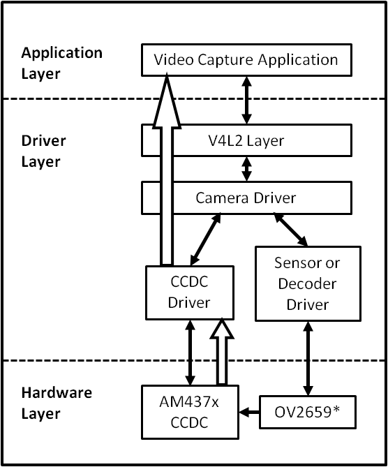
Capture Driver Component Overview
- Camera Applications
- Camera applications refer to any application that accesses the device node that is served by the Camera Driver. These applications are not in the scope of this design. They are here to present the environment in which the Camera Driver is used.
- V4L2 Subsystem
- The Linux V4L2 subsystem is used as an infrastructure to support the operation of the Camera Driver. Camera applications mainly use the V4L2 API to access the Camera Driver functionality. A Linux V4L2 implementation is used in order to support the standard features that are defined in the V4L2 specification.
- Videobuf2 Library
- This library is part of the V4L2 Layer. It provides helper functions to cleanly manage the video buffers through a video buffer queue object.
- Camera Driver
- The Camera Driver allows capturing video through an external sensor/decoder. It is a V4L2-compliant driver which provide access to the AM437x VPFE hardware feature. This driver conforms to the Linux driver model for power management. The camera driver is registered to the V4L2 layer as a master device driver. Any slave sensor/decoder driver added to the V4L2 layer will be attached to this driver through the new V4L2 sub-device interface layer. The current implementation supports only one slave device.
- Sensor/Decoder Driver
- The Camera Driver is designed to be AM437x VPFE module dependent, but platform and board independent. It is the sensor/decoder driver that manages the board connectivity. A decoder driver must implement the V4L2 sub-device interface. It should register to the V4L2 layer as a sub-device. Changing a sensor/decoder requires implementation of a new driver; it does not require changing the Camera Driver. Each sensor/decoder driver exports a set of IOCTLs to the master device through function pointers.
- CCDC library
- CCDC is a HW block, where it acts as a data input/entry port. It receives data from the sensor/decoder through parallel interface. The CCDC library exports API to configure CCDC module. It is configured by the master driver based on the sensor/decoder attached and desired output from the camera driver.
Source Location
- drivers/media/platform/ti_vpfe/
- AM437x VPFE Driver Sources
Kernel Configuration Options
The driver can be built as a static or dynamic module. When built as a dynamic module the driver is named ti_vpfe.ko.
By default VPFE support is built in to the 3.12 kernel when using omap2plus_defconfig.
$ make menuconfig ARCH=arm
- Select “Device Drivers” from the main menu.
...
...
Kernel Features  --->
Boot options  --->
CPU Power Management  --->
Floating point emulation  --->
Userspace binary formats  --->
Power management options  --->
[*] Networking support  --->
Device Drivers  --->
...
...
- Select “Multimedia support” from the menu and enter it.
...
...
[ ] ARM Versatile Express platform infrastructure
-*- Voltage and Current Regulator Support  --->
<*> Multimedia support  --->
    Graphics support  --->
<*> Sound card support  --->
    HID Devices  --->
[*] USB support  --->
...
...
- Select “V4L platform devices” from the menu.
--- Multimedia support
...
...
[ ]   Media PCI Adapters  ----
[*]   V4L platform devices -->
[ ]   Memory-memory multimedia devices ...
[ ]   Media test drivers  ----
      *** Supported MMC/SDIO adapters ***
< >   Cypress firmware helper routines
      *** Media ancillary drivers (tuners, sensors, i2c, frontends) ***
[ ]   Autoselect ancillary drivers (tuners, sensors, i2c, frontends)
      Encoders, decoders, sensors and other helper chips  --->
      Sensors used on soc_camera driver  ----
...
...
- Select “TI AM437x VPFE video capture driver” from the menu.
--- V4L platform devices
...
...
< > SoC camera support
<*>   TI AM437x VPFE video capture driver
...
...
- Selection of OV2659 Camera Sensor driver -
- Now go back to the Multimedia support level
De-select option Autoselect pertinent encoders/decoders and other helper chips and go inside Encoders/decoders and other helper chips
--- Multimedia support
...
...
[ ]   Autoselect ancillary drivers (tuners, sensors, i2c, frontends)
      Encoders, decoders, sensors and other helper chips  --->
      Sensors used on soc_camera driver  ----
...
...
- Select “OmniVision OV2659 sensor support” from the menu.
    *** Audio decoders, processors and mixers ***
...
...
< > Texas Instruments THS8200 video encoder
    *** Camera sensor devices ***
<*> OmniVision OV2659 sensor support
< > OmniVision OV7640 sensor support
...
...
Building as Loadable Kernel Module
- If you want to build the driver as a module, use <M> instead of <*> during menuconfig while selecting the drivers (as shown above). For more information on loadable modules refer Loadable Module HOWTO
DT Configuration
Example configuration in your board DTS file to enable VPFE instance 0. This an excerpt from the arch/arm/boot/dts/am437x-gp-evm.dts
&am43xx_pinmux {
       pinctrl-names = "default";
       pinctrl-0 = <&clkout2_pin &ddr3_vtt_toggle_default>;
...
...
       vpfe0_pins_default: vpfe0_pins_default {
               pinctrl-single,pins = <
                       0x1B0 (PIN_INPUT_PULLUP | MUX_MODE0)  /* cam0_hd mode 0*/
                       0x1B4 (PIN_INPUT_PULLUP | MUX_MODE0)  /* cam0_vd mode 0*/
                       0x1B8 (PIN_INPUT_PULLUP | MUX_MODE0)  /* cam0_field mode 0*/
                       0x1BC (PIN_INPUT_PULLUP | MUX_MODE0)  /* cam0_wen mode 0*/
                       0x1C0 (PIN_INPUT_PULLUP | MUX_MODE0)  /* cam0_pclk mode 0*/
                       0x1C4 (PIN_INPUT_PULLUP | MUX_MODE0)  /* cam0_data8 mode 0*/
                       0x1C8 (PIN_INPUT_PULLUP | MUX_MODE0)  /* cam0_data9 mode 0*/
                       0x208 (PIN_INPUT_PULLUP | MUX_MODE0)  /* cam0_data0 mode 0*/
                       0x20C (PIN_INPUT_PULLUP | MUX_MODE0)  /* cam0_data1 mode 0*/
                       0x210 (PIN_INPUT_PULLUP | MUX_MODE0)  /* cam0_data2 mode 0*/
                       0x214 (PIN_INPUT_PULLUP | MUX_MODE0)  /* cam0_data3 mode 0*/
                       0x218 (PIN_INPUT_PULLUP | MUX_MODE0)  /* cam0_data4 mode 0*/
                       0x21C (PIN_INPUT_PULLUP | MUX_MODE0)  /* cam0_data5 mode 0*/
                       0x220 (PIN_INPUT_PULLUP | MUX_MODE0)  /* cam0_data6 mode 0*/
                       0x224 (PIN_INPUT_PULLUP | MUX_MODE0)  /* cam0_data7 mode 0*/
               >;
       };


       vpfe0_pins_sleep: vpfe0_pins_sleep {
               pinctrl-single,pins = <
                       0x1B0 (DS0_PULL_UP_DOWN_EN | INPUT_EN | MUX_MODE7)  /* cam0_hd mode 0*/
                       0x1B4 (DS0_PULL_UP_DOWN_EN | INPUT_EN | MUX_MODE7)  /* cam0_vd mode 0*/
                       0x1B8 (DS0_PULL_UP_DOWN_EN | INPUT_EN | MUX_MODE7)  /* cam0_field mode 0*/
                       0x1BC (DS0_PULL_UP_DOWN_EN | INPUT_EN | MUX_MODE7)  /* cam0_wen mode 0*/
                       0x1C0 (DS0_PULL_UP_DOWN_EN | INPUT_EN | MUX_MODE7)  /* cam0_pclk mode 0*/
                       0x1C4 (DS0_PULL_UP_DOWN_EN | INPUT_EN | MUX_MODE7)  /* cam0_data8 mode 0*/
                       0x1C8 (DS0_PULL_UP_DOWN_EN | INPUT_EN | MUX_MODE7)  /* cam0_data9 mode 0*/
                       0x208 (DS0_PULL_UP_DOWN_EN | INPUT_EN | MUX_MODE7)  /* cam0_data0 mode 0*/
                       0x20C (DS0_PULL_UP_DOWN_EN | INPUT_EN | MUX_MODE7)  /* cam0_data1 mode 0*/
                       0x210 (DS0_PULL_UP_DOWN_EN | INPUT_EN | MUX_MODE7)  /* cam0_data2 mode 0*/
                       0x214 (DS0_PULL_UP_DOWN_EN | INPUT_EN | MUX_MODE7)  /* cam0_data3 mode 0*/
                       0x218 (DS0_PULL_UP_DOWN_EN | INPUT_EN | MUX_MODE7)  /* cam0_data4 mode 0*/
                       0x21C (DS0_PULL_UP_DOWN_EN | INPUT_EN | MUX_MODE7)  /* cam0_data5 mode 0*/
                       0x220 (DS0_PULL_UP_DOWN_EN | INPUT_EN | MUX_MODE7)  /* cam0_data6 mode 0*/
                       0x224 (DS0_PULL_UP_DOWN_EN | INPUT_EN | MUX_MODE7)  /* cam0_data7 mode 0*/
               >;
       };
...
...
};
...
...
&i2c1 {
       status = "okay";
       pinctrl-names = "default";
       pinctrl-0 = <&i2c1_pins>;
...
...
       ov2659@30 {
               compatible = "ti,ov2659";
               reg = <0x30>;


               port {
                       ov2659_0: endpoint {
                               remote-endpoint = <&vpfe0_ep>;
                               mclk-frequency = <12000000>;
                       };
               };
       };
};
...
...
&vpfe0 {
       status = "okay";
       pinctrl-names = "default", "sleep";
       pinctrl-0 = <&vpfe0_pins_default>;
       pinctrl-1 = <&vpfe0_pins_sleep>;


       /* Camera port \*/
       port {
               vpfe0_ep: endpoint {
                       remote-endpoint = <&ov2659_0>;
                       if_type = <2>;
                       bus_width = <8>;
                       hdpol = <0>;
                       vdpol = <0>;
               };
       };
};
- remote-endpoint is a reference to the i2c sensor node. This is used during sub-device registration.
- if-type defines the interface type used <0> BT656, <2> RAW.
- bus_width defines the number of data pins actually connected between the camera and the vpfe module. Only 2 values are supported 8 and 10. Pre-Beta boards had 10 data pins connected, Beta (and later) have 8 data pins connected which is a hardware level optimization reducing memory bus bandwidth and eliminating post-processing to compact the captured data.
- hdpol when set to 1 is used to invert the Hsync polarity
- vdpol when set to 1 is used to invert the Vsync polarity
Driver Usage
As seen previously the driver create a /dev/videoX device node when a sub-device is successfully registered. The device node provide access to the driver following a standard V4L2 API.
The driver support the following system calls and V4L2 ioctls:
open(), close(), mmap(), munmap() and ioctl()
| V4L2 ioctls | Definition |
|---|---|
| VIDIOC_REQBUFS | Allocating Memory Buffers |
| VIDIOC_QUERYBUF | Getting Buffer’s Physical Address |
| VIDIOC_QUERYCAP | Query Capabilities |
| VIDIOC_ENUMINPUT | Input Enumeration |
| VIDIOC_S_INPUT | Set Input |
| VIDIOC_G_INPUT | Get Input |
| VIDIOC_ENUMSTD | Standard Enumeration |
| VIDIOC_QUERYSTD | Query Standard |
| VIDIOC_S_STD | Set Standard |
| VIDIOC_G_STD | Get Standard |
| VIDIOC_ENUM_FMT | Format Enumeration |
| VIDIOC_ENUM_FRAMESIZES | Frame Size Enumeration |
| VIDIOC_S_FMT | Set Format |
| VIDIOC_G_FMT | Get Format |
| VIDIOC_TRY_FMT | Try Format |
| VIDIOC_QUERYCTRL | Query Control* |
| VIDIOC_S_CTRL | Set Control* |
| VIDIOC_G_CTRL | Get Control* |
| VIDIOC_QBUF | Queue Buffer |
| VIDIOC_DQBUF | Dequeue Buffer |
| VIDIOC_STREAMON | Stream On |
| VIDIOC_STREAMOFF | Stream Off |
| VIDIOC_CROPCAP | Query Cropping Capabilities+ |
| VIDIOC_S_CROP | Set Crop Parameters+ |
| VIDIOC_G_CROP | Get Current Cropping Parameters+ |
Table: Supported ioctls
There are plenty of generic V4L2 capture applications available:
There is also a media controller sample application which can be used as an example to configured sensor/decoder sub-device:
Debugging
As vpfe driver is based on the V4L2 framework, framework level tracing can be enable as follows:
- echo 3 >/sys/class/video4linux/video1/dev_debug This allows V4L2 ioctl calls to be logged.
- echo 3 > /sys/module/videobuf2_core/parameters/debug This allows VB2 buffers operation to be logged.
In addition vpfe also has specific debug log which can be enabled as follows:
- echo 3 > /sys/module/am437x_vpfe/parameters/debug