3.5.2.1. PRU Hands-on Labs
- Lab Configuration
- LAB 1: Toggle LED with PRU GPO
- LAB 2: Read Push Button Switch on PRU0 GPI & Toggle LED with PRU1 GPO
- LAB 3: Temperature Monitor
- LAB 4: Introduction to Linux driver
- LAB 5: RPMsg Communication between ARM and PRU
- Build the PRU Firmware - Using CCSv6
- Build the PRU Firmware - Using the Provided Makefile
- Build the RPMsg Client Sample Driver
- Copy files to the target file system
- Part 1: Kernel space communication
- What just happened?
- Part 2: User Space Communication
- Part 3: User Space Application
- What just happened?
- LAB 6: Blinking LEDs with RPMsg from Linux User Space
The labs provided on this page will give you a hands on tutorial of the PRU, C-compiler, and Linux driver. Each of the following sections below will walk you through a particular Lab exercise, including the step-by-step instructions to complete the lab.
Note
In this guide commands to be executed for each step will be marked in BOLD.
Note
This guide was written using Code Composer Studio 6 (CCSv6). However, the latest version of Code Composer Studio may be used.
3.5.2.1.1. Lab Configuration
The following are the hardware and software configurations for this lab. The steps in this lab are written against this configuration. The concepts of the lab will apply to other configurations but will need to be adapted accordingly.
3.5.2.1.1.2. Software
- Linux Processor SDK installed. This lab assumes the latest Linux Processor SDK is installed in /home/sitara. If you use a different location please modify the below steps accordingly.
- The PRU Software Support Package is now included in the ‘example-applications/pru-icss-x.y.z/’ folder of the Linux Processor SDK (as of v2.0.2.11). If you are using RTOS or running Windows on your development machine, you can download the support package from the git repository here. This lab assumes that the software package is installed in /home/sitara/<ti-sdk...>/example-applications/pru-icss-x.y.z. However, the notation *<PRU_SW_PATH>* will be used throughout the labs to reference this assumed installation location. If you use a different location please modify the steps below.
- CCSv6
- PRU Code Generation Tools (also available through the CCS App Center)
3.5.2.1.1.3. Supported Platforms
This hands-on guide is focused on the AM335x processor on the Beaglebone Black due to the availability of the PRU cape for this platform as well as access to the PRU pins externally. However, the concept of loading/running firmwares described here will translate to any Sitara device that supports general development with a PRU-ICSS or PRU_ICSSG.
3.5.2.1.2. LAB 1: Toggle LED with PRU GPO
Objective
Toggle an LED using the PRU0 R30 GPO in Direct Output Mode (default).
- Compile PRU code
- Load PRU code using CCS
3.5.2.1.2.1. Create & Build the PRU Project
Note
Before beginning, ensure that the kernel is not booting and/or already up and running. BeagleBone Black has an eMMC device with a kernel pre-built and flashed ready for boot; however, if the kernel loads prior to our connection to the ARM in CCS then you may experience issues with the debugger. These are primarily caused by the kernel enabling the MMU. Use a minicom console to stop U-Boot to prevent the kernel from booting. To work around this, first try popping out the microSD card if one is inserted. If the blue LEDs on the BBB are toggling when power is applied, then the board is still booting off the eMMC. On the BBB opposite the RJ-45 (Ethernet) connector, there is a push button almost directly under the audio jack that may be difficult to access with the PRU cape on. Press and hold this while power is applied, then release. You should no longer see the flashing lights.
Launch CCSv6 and select the default Workspace.
Create a new PRU project.
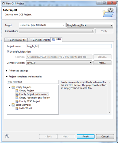
Select File->New->CCS Project.
In the far-right dropdown next to Target, select BeagleBone_Black.
Select PRU tab, specify a Project Name (toggle_led works well), and verify that Compiler version is TI v2.1.0 or higher.
Select Finish.
Main.c should open automatically. Let’s start creating our example code!
Include stdint and pru_cfg headers.
Declare the r30 register.
include <stdint.h>
include <pru_cfg.h>

volatile register uint32_t __R30;
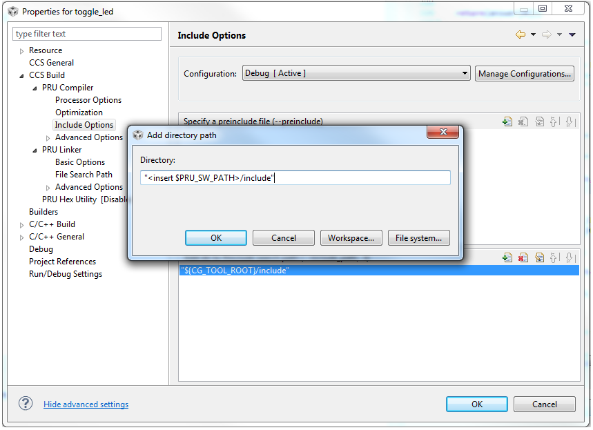
Add the include path for the header files so that the compiler can find them.
Select Project->Properties.
Select Build->PRU Compiler->Include Options.
In the box marked “Add dir to #include search path” click the file icon with a green +.
Specify the directory to the include file which for the BeagleBone Black is <PRU_SW_PATH>/include/am335x
Note
If there is already a ${CCS_BASE_ROOT}/pru/include directory, delete it by clicking the file icon with a red X.
Now we will begin coding inside the main function.
Declare a temporary variable called gpo to represent GPO values.
Set GPI and GPO to Mode 0 (Direct Output).
Create an infinite loop which toggles the GPO pin(s) and delays one half second.
void main(){

   volatile uint32_t gpo;
   /* GPI Mode 0, GPO Mode 0 */
   CT_CFG.GPCFG0 = 0;

  /* Clear GPO pins */
   __R30 = 0x0000;

   while(1){
        gpo = __R30;
        gpo ^= 0xF;
        __R30 = gpo;
        __delay_cycles(100000000); // half-second delay
   }
}
Add the linker command file.
Delete AM335x.cmd from the project folder, if it was added automatically.
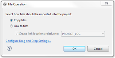
Select Project->Add Files...
Navigate to the <PRU_SW_PATH>/labs/lab_1 folder and select the AM335x_PRU.cmd file.
Note
Select Copy files and OK in the File Operation dialog box that appears when file is selected.
Build the project.
- Select Project->Build All.
- This should now compile successfully! If not, correct any errors until build completes.
3.5.2.1.2.2. Load the PRU Firmware
Select View->Target Configurations to see a list of available configurations. Note that this list may be empty.
To create a new one right click in the white space in the Target Configurations window and select New Target Configuration.
Specify a filename (such as BBB_SDXDS200_pru.ccxml if using an XDS200 emulator) and select Finish.
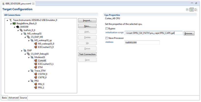
After the file opens select your emulator in the Connection drop-down.
Under Board or Device select the BeagleBone_Black.
Click the Advanced tab at the bottom of that window, select the CortxA8 core, and browse to the PRU_CAPE.gel file (found in <PRU_SW_PATH>/pru_cape).
Click Save and close this file.
Let’s launch the debugger and load the code!
In the “Target Configurations” view, right click the Target Configuration file we just created and select Launch Selected Configuration. Note that Launch Selected Configuration might not appear if you right click the file in a view other than “Target Configurations”.
After it loads right click on the CortxA8 core and select Connect Target.
Run the GEL script under Scripts->Initialization->PRU_Cape_Init.
Note
This runs basic initialization code for pin muxing.
After the script runs, right click on the CortxA8 core and select Disconnect Target.
Right click on the PRU_0 core and select Connect Target.
Load the example you just build by selecting Run->Load->Load Program.
Select Browse, navigate to the project directory (by default /home/sitara/workspace_6.0/toggle_led/debug/) and select the toggle_led.out file.
Select the green arrow to run your code.
You should now see the LEDs toggle!
When you’re all done enjoying your work, terminate the debug session using the big red square.
3.5.2.1.3. LAB 2: Read Push Button Switch on PRU0 GPI & Toggle LED with PRU1 GPO
Objective
PRU multi-core communication.
3.5.2.1.3.1. Build the PRU Firmware
Launch CCSv6 and select the default Workspace.
Create two new PRU projects – one for PRU0 and one for PRU1.
- Select File->New->CCS Project.
- In the far-right dropdown next to Target, select BeagleBone_Black.
- Select PRU tab, specify a Project Name (e.g., button_led_0 & button_led_1), and verify that Compiler version is TI v2.1.0 or higher.
- Select Finish.
- Remember to create two separate projects, button_led_0 & button_led_1.
Copy the button_led_n.c and AM335x_PRU.cmd from the <PRU_SW_PATH>/labs/lab_2 directory into the new projects.
- You can do this by selecting File->Open File, navigating to the button_led_n.c and AM335x_PRU.cmd and copying them to the project.
- Alternatively, you can browse to the directory in an explorer window and drag/drop them as you would in Windows, or use Project->Add Files...
Remove main.c from the projects. main() has been implemented in button_led_n.c
Now we will begin modifying the code in button_led_0.c
Include the pru_intc.h header file. Open it and examine the contents for a better understanding of the pruIntc structure. You should find it in <PRU_SW_PATH>/include
Notice the new declaration for the r31 register as we did previously for the r30 register. This allows us to directly access this register to generate interrupts.
Notice the declarations for the interrupt we will generate to signal to PRU1 that SW1 was pressed. The PRU cores can generate interrupts manually using events 16-31; however, these are mapped to bits [3:0] in the r31 register. Additionally we have to trigger bit 5 to strobe the interrupt. As an example, we pass 0b000 ORed with 0x20 to generate an interrupt on event 16. For more information see the definition of r31 writes in the device specific TRM.
/* Defines */ /* PRU0-to-PRU1 interrupt */

define PRU0_PRU1_EVT (16)
define PRU0_PRU1_TRIGGER (__R31 = (PRU0_PRU1_EVT - 16) | (1 << 5))
Define the GPI offset for SW1 which is located in GPI5.
/* SW1 offset */
define SW1 (1 << 5)
Go to the configIntc function. This function is mostly intact, but you will need to fill out the register values in order to configure the interrupt. Refer to the PRU INTC register descriptions in the device specific TRM for register layouts. For this exercise you will want to configure these registers such that:
Event 16 is mapped to Channel 1
Channel 1 is mapped to Host 1
Ensure event 16 is clear
Enable event 16
Enable Host 1
Globally enable interrupts
/* Map event 16 to channel 1 */ CT_INTC.CMR4_bit.CH_MAP_16 = 1;

/* Map channel 1 to host 1 */ CT_INTC.HMR0_bit.HINT_MAP_1 = 1;

/* Ensure event 16 is cleared */ CT_INTC.SICR = 16;

/* Enable event 16 */ CT_INTC.EISR = 16;

/* Enable Host interrupt 1 */ CT_INTC.HIEISR |= (1 << 0);

/* Globally enable host interrupts */ CT_INTC.GER = 1;
Note
Remember that you can use the CodeCompletion feature within CCS for a list of available registers and bit fields in the structure! To access it simply hit Ctrl+space after the dot (it should also open automatically when you type the dot).
Within the while(1) loop we are going to begin polling the status of the R31 register to determine if the button has been pressed. When the button is pressed, you will generate the interrupt to PRU1 and wait 500ms as a cheap ‘debounce’.
while(1){
   if ((__R31 & SW1) != SW1){
       /* Interrupt PRU1, wait 500ms for cheap "debounce" */
       /* TODO: Trigger interrupt - see #defines */
       __delay_cycles(100000000); /* 500ms @ 200MHz */
Note
The switches are active low so we are looking for it to go low.
Save the file, and then add the include directory to the Include Search Path to the button_led_0 project.
Select Project->Properties.
Select Build->PRU Compiler->Include Options.
In the box marked “Add dir to #include search path” click the file icon with a green +.
Specify the directory to the include file which for the BeagleBone Black is <PRU_SW_PATH>/include/am335x
Note
If there is already a ${CCS_BASE_ROOT}/pru/include directory, delete it by clicking the file icon with a red X.
Select OK and build the project. This should now compile successfully! If not, correct any errors until build completes.
Let’s go modify the code in button_led_1.c
Include the pru_intc.h header file.
Notice the define for HOST1_MASK. Hosts 0 and 1 are automatically mapped to bits 30 and 31, respectively, in the r31 register. To view the status of Host 1 we mask out the lower 31 bits.
Create a define to toggle the BLUE LED which is located on PRU1 GPO 3.
define TOGGLE_BLUE (__R30 ^= (1 << 3))
Notice the while(1) loop which is waiting for the Host 1 interrupt.
/* Spin in loop until interrupt on HOST 1 is detected */
while(1){

    if (__R31 & HOST1_MASK){
        TOGGLE_BLUE;
Once the interrupt is received we need to clear it by clearing the event.
/* Clear interrupt event */ CT_INTC.SICR = 16;
Save the file, and then add the include directory to the Include Search Path of the button_led_1 project as before.
Select OK and then build the project. This should now compile successfully! If not, correct any errors until build completes.
3.5.2.1.3.2. Load the PRU Firmware
- Let’s launch the debugger and load the code!
- Right click the Target Configuration file we created earlier and select Launch Selected Configuration.
- After it loads right click on the CortxA8 core and select Connect Target.
- Run the GEL script under Scripts->Initialization->Init.
- Right click on the PRU0 core and select Connect Target.
- Load the example you just built by selecting Project->Load->Load Program, then navigate to the project for button_led_0 and select button_led_0.out
- Select the green arrow to run your code.
- Right click on the PRU1 core and select Connect Target.
- Load the second example you built by selecting Run->Load->Load Program, then navigate to the project for button_led_1 and select button_led_1.out
- Select the green arrow to run your code.
- You should now see the other BLUE LED toggle when you press SW1! If not, keeping reading...
3.5.2.1.3.3. Debug the PRU Firmware
Do you see the LED light up when you press SW1? If not, it sounds like a problem you will have to debug...
For this exercise we are going to take it easy on you and provide the answer; however, first a quick explanation of why your code is not working.
This is a very tightly controlled while loop containing only 4 assembly instructions. Because every instruction is single cycle it will only take 4 cycles to complete. Normally this would not be an issue, but there is a slight delay in the time it takes for our write to the SICR to actually clear event 16.
To work around these we need to add a very small CPU delay after the write to SICR. We chose 5 cycles even though it is overkill, but we wanted to be safe and guarantee that the event was cleared before the loop cycled back.
/* Clear interrupt event */ CT_INTC.SICR = 16;
/* Delay to ensure the event is cleared in INTC */ __delay_cycles(5);
Without this delay, r31[31] is still high when the loop repeats and checks the status of the interrupt. Since the event has not been cleared yet, the GPO pin is instantly toggled off before we can see it toggled on.
Rebuild the project, reload and observe. The LED should now toggle when you press SW1! No, really, you should. If you don’t, this time it really is a bug.
3.5.2.1.4. LAB 3: Temperature Monitor
Objective
Design a temperature monitor application on the PRU that periodically measures ambient temperature and toggles a Red LED if the temperature increases and a Blue LED if the temperature decreases.
- Step through PRU code in CCS
3.5.2.1.4.1. Design & Build the PRU Firmware
Go through the
PRU Training session: Designing a PRU Application. This interactive training session introduces a step-by-step design process and walks through using this process to design a Temperature Monitor application for the PRU. The Temperature Monitor application based on the training session is already written for you. However, you can also try writing the Temperature Monitor application yourself! The rest of this lab will take a closer look at the source code, run it on the PRU, and measure PRU cycles using the CCS debugger.Launch CCSv6 and select the default Workspace.
Create two new PRU projects – one for PRU0 and one for PRU1.
- Select File->New->CCS Project.
- Next to Target select BeagleBone_Black.
- Select PRU tab, specify a new Project Name (e.g., temp_monitor_slave_0 & temp_monitor_master_1), verify that Compiler version is TI v2.1.0, and select “Empty Project.” Note: If “Empty Project (with main.c)” is selected, you will need to delete main.c in the project directory (added by default).
- Select Finish.
- Remember to create two separate projects.
Copy the temp_monitor_master_1.c, PRU_1wire.h, AM335x_PRU.cmd, and resource_table_empty.h from the <PRU_SW_PATH>/pru_cape/pru_fw/PRU_HDQ_TempSensor1 directory into the new temp_monitor_master_1 project
- You can do this by selecting File->Open File, navigating to the temp_monitor_master_1.c, PRU_1wire.h, AM335x_PRU.cmd, and resource_table_empty.h; and copying them to the project.
- Alternatively, you can browse to the directory in an explorer window and drag/drop them as you would in Windows.
Copy the temp_monitor_slave_0.c, PRU_1wire.h, AM335x_PRU.cmd and resource_table_empty.h from the <PRU_SW_PATH>/pru_cape/pru_fw/PRU_HDQ_TempSensor0 directory into the new temp_monitor_slave_0 project
For each project, add the include directory to the Include Search Path.
Select Project->Properties.
Select Build->PRU Compiler->Include Options.
In the box marked “Add dir to #include search path” click the file icon with a green +.
Specify the directory to the include file which for the BeagleBone Black is <PRU_SW_PATH>/include/am335x
Note
If there is already a ${CCS_BASE_ROOT}/pru/include directory, delete it by clicking the file icon with a red X.
Build each project.
Let’s take a look at the code in temp_monitor_master_1.c
Notice the mapping for the interrupt controller in the intc_config function. Both lab 2 & 3 use the same basic steps to configure the INTC. However, the temp monitor implementation in lab 3 uses non-indexed registers (i.e. ESR0, SECR0, etc), whereas lab 2 used the indexed registers (i.e. EISR, SICR, etc). The indexed and non-indexed registers offer two approaches to accomplish the same end result.
Review the event to channel to host mapping. Note “Host 0” will be used to interrupt the PRU0 slave and “Host 1” will be used to interrupt the PRU1 master.
Notice that after the PRU master code configures the INTC and PWM, it waits on an interrupt from the PRU slave that indicates the slave has completed its own configuration steps and is ready to start communicating with the temperature sensor. Does this impact the order that we need to run each PRU core?
Note
If the PRU INTC is not configured before the PRU slave starts running, the event generated by the PRU slave will not be detected and the PRU master will be perpetually waiting for this event. To eliminate this configuration dependency, an alternate solution would be to have the ARM pre-configure the PRU INTC prior to enabling the PRU cores.
Notice how the PRU master code handles monitoring for multiple interrupts. The code first detects that an event has generated on the specific Host interrupt and then checks what is the highest priority event that has occurred on this Host interrupt.
/* Detect interrupt */ while((__R31 & 0x80000000) == 0){}

/* Identify highest priority event */ int_val = CT_INTC.HIPIR1;
Note
The priority for a given interrupt can be controlled through the PRU INTC system event and channel mapping— lowered numbered events and channels have higher priority. In our temp monitor implementation, which event will have the highest priority?
Let’s go look at the code in temp_monitor_slave_0.c
Notice that as observed in the PRU master code, the PRU slave first configures the IEP Timer and DigIO and then interrupts the PRU master to signal that it’s ready to communicate with the temperature sensor.
Notice that in the iep_timer_config function, the PRU slave stores different increments of time required by 1-wire protocol (i.e. 480 us, 60 us, 15 us, 1 us) as separate PRU IEP CMP values. The 1-Wire Protocol functions (write_0, write_1, read, init) then call the timer function that detects an IEP interrupt for the appropriate CMP value.
Note
In timer function we add a very small CPU delay after clearing the IEP timer event source and before clearing the PRU INT— similar to lab 2. Without this delay, the CMP_STATUS is still set when the INTC status is cleared and the INTC will immediately re-detect and set the event.
/* Clear IEP Timer system event */ CT_IEP.CMP_STATUS = (1 << wait480us);
__delay_cycles(4);
CT_INTC.SECR0 = (1 << PRU_IEP_EVT);
Notice that the 1-Wire Protocol functions (write_0, write_1, read, init) configure the IEP DigIO for tri-state mode to allow the 1-wire signal to float “high”. For example in the init function:
/* Drive OUT_1WIRE low */ CT_IEP.DIGIO_DATA_OUT_EN = 0x0;
timer(wait480us);

/* Set OUT_1WIRE in tri-state mode */ CT_IEP.DIGIO_DATA_OUT_EN = OUT_1WIRE;
Notice that the other steps in the PRU slave code match the diagram that we architected in Design Step 5.
3.5.2.1.4.2. Load the PRU Firmware
Let’s launch the debugger and load the code!
Right click the Target Configuration file we created earlier and select Launch Selected Configuration.
After it loads right click on the CortxA8 core and select Connect Target.
Run the GEL script under Scripts->Initialization->Init.
Right click on the PRU1 core and select Connect Target.
Load the example you just built by selecting Project->Load->Load Program, then navigate to the project for temp_monitor_master_1 and select temp_monitor_master_1.out
Select the green arrow to run your code.
Note
PRU1 needs to be run first because of the INTC configuration dependency.
Right click on the PRU0 core and select Connect Target.
Load the second example you built by selecting Project->Load->Load Program, then navigate to the project for temp_monitor_slave_0 and select temp_monitor_slave_0.out
Select the green arrow to run your code.
You should now see the RED or BLUE LED toggle depending on the change in temperature! (Note neither LED will be illuminated if there is no change in temperature.)
Place either your thumb or the palm of your hand over TEMP1 temperature sensor to see the temperature rise and the RED LED illuminated. Remove your thumb or palm to see the temperature fall and the BLUE LED illuminated.
3.5.2.1.4.3. Debug the PRU Firmware
- During our design discussion, we were unsure how many PRU cycles the
CRC calculation would consume. Let’s actually measure the PRU cycles
using the CCS debugger!
- Click on each PRU core and select the yellow pause button to suspend each core.
- Reload the code for each PRU core by selecting Project->Load->Reload Program.
- Click on the PRU0 core.
- Set a breakpoint in temp_monitor_slave_0.c, line 139 when the PRU calculates the CRC.
- Click on the PRU1 core and select the green arrow to run your code.
- Click on the PRU0 core and select the green arrow to run your code
- When the PRU0 core breaks on line 139, open the Registers window and enable the PRU Cycle Counter in the PRU0_CTRL.CTRL[CTR_EN]. If the Registers window is not already open, select View->Registers
- Select Run->Step Over to step over this line.
- In the Registers window, read the value in PRU0_CTRL.CYCLE register. This is the number of PRU cycles required to calculate the CRC for each byte.
3.5.2.1.5. LAB 4: Introduction to Linux driver
Objective
To test the Linux remoteproc driver. We will first add a resource table to the projects we created earlier in lab 2, rebuild those projects, load the .out files into the target filesystem and then use the remoteproc driver to load that code into the PRU cores.
Note
Starting in Linux Processor SDK 2.0.2.11 the remoteproc and rpmsg drivers are enabled by default in the provided kernel configuration and default binaries. Therefore, it is no longer necessary to modify the .config in order to load firmwares into the PRU cores.
3.5.2.1.5.1. Build the PRU Firmware
Launch CCSv6 and select the default Workspace.
Open the button_led_0 project.
In the button_led_0 project, select File->Open File and copy in the resource_table_0.h file from <PRU_SW_PATH>/labs/lab_4 or use Project->Add Files... to add the file to the project and copy it into the workspace.
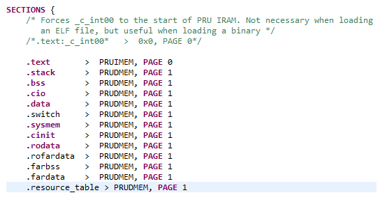
In the AM335x.cmd file, add a line telling the linker where to place the new .resource_table section.
In button_led_0.c include the resource_table_0.h file.
include <stdint.h>
include <pru_cfg.h>
include <pru_intc.h>
include "resource_table_0.h"
Rebuild the project and ensure that it builds correctly without errors.
Open the button_led_1 project.
- Select File->Open File and copy in the resource_table_1.h file from <PRU_SW_PATH>/labs/lab_4 or use Project->Add Files... and copy the file into the workspace.
- In button_led_1.c include the resource_table_1.h file.
- Rebuild the project and ensure that it builds correctly without errors.
- You may choose to launch the debugger and verify that both projects run without issues.
3.5.2.1.5.2. Configure the Kernel
Note
This step is needed before building the kernel, kernel modules, device tree files, etc. For more information about these steps, see the Kernel Users Guide.
Prepare to build the kernel, kernel modules, device tree files, etc
Export the terminal PATH to where the cross compiler toolchain files can be found. This can be found in the linux-devkit/sysroots/<Arago Linux>/user/bin of your SDK directory where your Arago Linux version may be x86_64-arago-linux. Be sure to include /home/<user>/ before your SDK directory.
export PATH=$PATH:<SDK path>/linux-devkit/sysroots/<Arago
Linux>/usr/bin/
Note
You will have to do this each time you open a new terminal.
Clean the kernel sources
make ARCH=arm CROSS_COMPILE=arm-linux-gnueabihf- distclean
Configure the kernel
make ARCH=arm CROSS_COMPILE=arm-linux-gnueabihf-
tisdk_am335x-evm_defconfig
3.5.2.1.5.3. Build the Linux Kernel and remoteproc Driver
- Beginning with Linux Processor SDK v2.0.2.11, the remoteproc and rpmsg modules are enabled by default and included out of the box in the Linux Processor SDK. These instructions assume users use the prebuilt kernel and driver modules used in the create SD card script, so we do not need to rebuild the kernel and driver modules. See section “Copy files to the target filesystem” for information on using the create SD card script. More information on enabling the remoteproc and rpmsg modules may be found in the “How to Enable PRU Support in Kernel” section here.
3.5.2.1.5.4. Modify Device Tree Files to Account for PRU Cape
The SDK includes example device tree source files for several TI and community boards, like the Beaglebone Black. Since the PRU cape requires certain pin muxing and configuration to be configured to be usable in Linux, this requires modifications to the device tree files.
Modify to SDK provided DTS (devicetree source) files to account for the PRU cape.
Copy the am335x-boneblack-prucape.dtsi from the <PRU_SW_PATH>/pru_cape directory to arch/arm/boot/dts.
In your kernel source tree, open arch/arm/boot/dts/am335x-boneblack.dts for editing.
Add the below line to include the PRU Cape DTS file to the bottom of the am335x-boneblack.dts file. #include “am335x-boneblack-prucape.dtsi”
Note
It is very important that this edit be made at the end of the file. Not included with the other include files. Device Trees work with an “overlay” mentality, applying changes as they are found serially to a “tree” structure. We need the edits made for the PRU cape to be applied last.
Save the file.
Compile the DTS file: make ARCH=arm CROSS_COMPILE=arm-linux-gnueabihf- am335x-boneblack.dtb
3.5.2.1.5.5. Copy files to the target filesystem
So far, we’ve built the PRU firmware and the modified device tree. Now, we need to copy these files to the target filesystem. We’re going to keep things simple and make some assumptions. If you’ve done things differently in your set up, then you’ll need to adapt these instructions to your set up.
We need to get the new device tree and PRU firmware running on the Beaglebone Black. The easiest way to do this is with an SD card. There are lots of other alternatives (boot from TFTP with an initramfs, boot from TFTP and mount the FS over NFS, copy everything to the Beaglebone Black’s eMMC, etc.). Feel free to adapt these instructions to your desired setup.
Use the script included with the SDK to create a bootable SD card.
You can find instructions on this process at the Linux SD Card Creation Guide.
Once the card is created, mount it on your Linux host to copy the files to it.
The rootfs partition on the SD card contains the target filesystem. Copy the files from your development host to the SD card:
- Copy the button_led_0.out and button_led_1.out from your CCS workspace where they were built to the /lib/firmware/pru directory of the rootfs partition.
- Make a copy of am335x-boneblack.dtb, in the same directory arch/arm/boot/dts, and change its name to am335x-boneblack-prucape.dtb.
- Copy the am335x-boneblack-prucape.dtb from arch/arm/boot/dts to the boot directory of the rootfs partition of the SD card.
- Change the “am335x-boneblack.dtb” symlink in the rootfs/boot directory to point to the am335x-boneblack-prucape.dtb instead of the default. sudo ln -f -s am335x-boneblack-prucape.dtb am335x-boneblack.dtb
- Use the sync command to make sure all of your changes have been committed to the SD card.
3.5.2.1.5.6. Boot the new device tree and FS on the Target
Now we’re ready to try everything out.
Move the SD card from the host PC to the target board.
Boot the Beaglebone Black from the SD Card by holding down the “boot” button while applying power with either the USB cable or a dedicated 5V power source. The “boot” button may be difficult to get to with the PRU cape in place. It is right above the micro SD card slot.
Wait for the kernel to boot. At the prompt, login with “root” and no password.
Use the remoteproc sysfs interface to specify which firmwares you want the remoteproc driver to load
echo 'pru/button_led_0.out' > /sys/class/remoteproc/remoteproc1/firmware
echo 'pru/button_led_1.out' > /sys/class/remoteproc/remoteproc2/firmware
Once again use the remoteproc sysfs interface to load and then run the PRU cores
echo 'start' > /sys/class/remoteproc/remoteproc1/state
echo 'start' > /sys/class/remoteproc/remoteproc2/state
Observe the LEDs blink.
Once ‘start’ has been echoed into the ‘state’ attribute the remoteproc firmware will load the PRU cores and then run them. You should be able to see the LED toggle as you press the switch as before in Lab 2.
If you would like to unload and then reload the PRU cores, use the commands below:
echo 'stop' > /sys/class/remoteproc/remoteproc1/state
echo 'stop' > /sys/class/remoteproc/remoteproc2/state
echo 'start' > /sys/class/remoteproc/remoteproc1/state
echo 'start' > /sys/class/remoteproc/remoteproc2/state
3.5.2.1.6. LAB 5: RPMsg Communication between ARM and PRU
- Build the PRU Firmware - Using CCSv6
- Build the PRU Firmware - Using the Provided Makefile
- Build the RPMsg Client Sample Driver
- Copy files to the target file system
- Part 1: Kernel space communication
- What just happened?
- Part 2: User Space Communication
- Part 3: User Space Application
- What just happened?
Objective
This lab will show how to build a firmware that uses the rpmsg_lib PRU library in order to enable communication with the ARM core running Linux. Part 1 will walk you through creating the PRU firmware and loading the modules necessary for PRU to kernel space communication. Part 2 will use a different Linux module in order to expose a user space interface for PRU communication. Part 3 will show how to create a user space C application that can send and receive messages to a PRU core. This lab expects to use the remoteproc Linux driver to load the PRU firmware. Please complete and understand LAB 4: Introduction to Linux driver before beginning this lab.
3.5.2.1.6.1. Build the PRU Firmware - Using CCSv6
Launch CCSv6 and select the default Workspace.
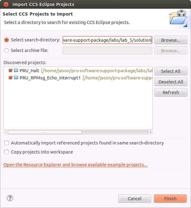
Import the PRU_RPMsg_Echo_Interrupt1 and PRU_Halt projects from the lab_5 solution folder.
Project->Import CCS Projects...
Click Browse...
Navigate to <PRU_SW_PATH>/labs/lab_5/solution and click OK (where <PRU_SW_PATH> is the path to your PRU Software Support Package installation).
Click the checkbox next to both projects in order to select them and then click Finish. (For this lab, you do not need to check ‘Automatically import referenced projects...’ or ‘Copy project into workspace’.)
Make sure that the compiler include options for both projects point to the include folders provided with the software package.
Right-click on each project in the Project Explorer and then click Properties.
Expand Build then expand PRU Compiler and then click on Include Options.
Make sure that ”../../../../../include” is there as an include path.
Also make sure that ”../../../../../include/am335x” is there as an include path.
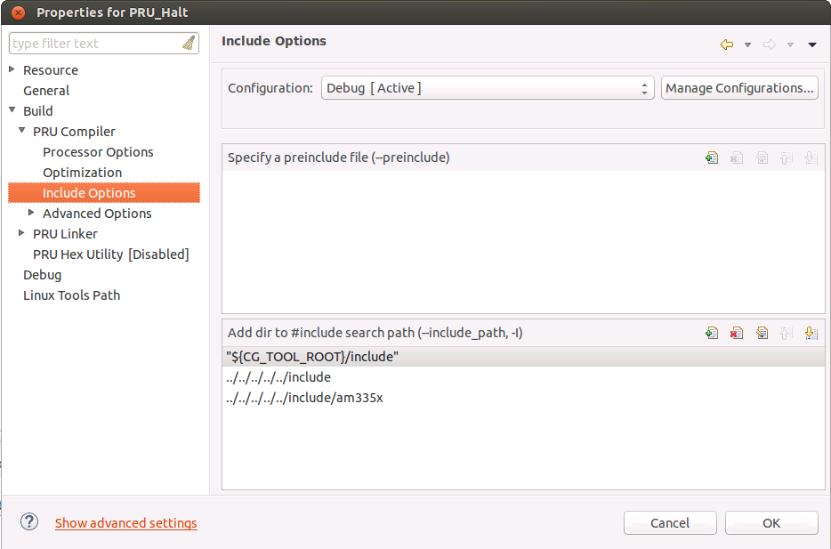
Click OK.
Make sure that the rpmsg_lib library is added in the PRU_RPMsg_Echo_Interrupt1 project.
Right-click on PRU_RPMsg_Echo_Interrupt1 in the Project Explorer and then click Properties.
Expand Build then expand PRU Linker and then click on File Search Path.
Make sure that ”../../../../../lib/rpmsg_lib.lib” is there as an included library file.
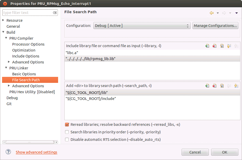
Click OK.
Build each project and make sure there are no errors.
- Right-click on each project in the Project Explorer and then click Rebuild Project.
3.5.2.1.6.2. Build the PRU Firmware - Using the Provided Makefile
Open a command prompt or terminal window.
Set the PRU_CGT environment variable to point to the PRU code generation tools folder. This folder is included in the Linux Processor SDK v2.0.2.11 and newer.
- Linux: export PRU_CGT=<path_to_Linux_proc_sdk>/linux-devkit/sysroots/x86_64-arago-linux/usr/share/ti/cgt-pru
- Windows: set PRU_CGT=C:/TI/ccs_v6_<version>/ccsv6/tools/compiler/ti-cgt-pru_2.1.0
Change to the PRU_RPMsg_Echo_Interrupt1 directory.
- cd <PRU_SW_PATH>/labs/lab_5/solution/PRU_RPMsg_Echo_Interrupt1 (where <PRU_SW_PATH> is the path to your PRU Software Support Package installation).
Clean the previously generated files, if they exist.
- make clean
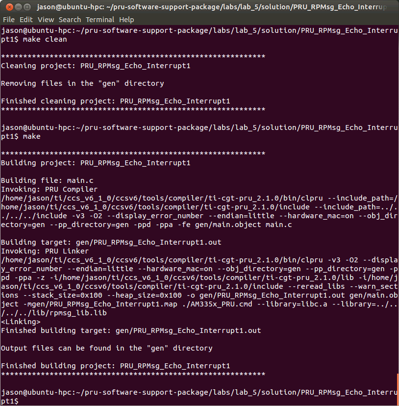
Build the project.
- make
Change to the PRU_Halt directory and repeat the make clean and make commands. The generated project files will be available in a folder named gen in each project directory. The output for each project should be similar to the below screen shot:
3.5.2.1.6.3. Build the RPMsg Client Sample Driver
Open a terminal on your Linux development machine and navigate to the Linux source directory.
- cd <SDK path>/board-support/linux<version> (where <SDK path> is the location of your Processor SDK installation)
Enable the RPMsg Client Sample driver in the kernel config.
Note
Be sure that you have already followed all the instructions in LAB 4: Introduction to Linux driver. If you opened a new terminal window, you will have to export the PATH again.
make ARCH=arm CROSS_COMPILE=arm-linux-gnueabihf- distclean
make ARCH=arm CROSS_COMPILE=arm-linux-gnueabihf- tisdk_am335x-evm_defconfig
make ARCH=arm CROSS_COMPILE=arm-linux-gnueabihf- menuconfig
Navigate to Kernel hacking->Sample kernel code and type ‘Y’
After typing ‘Y’ to include Sample kernel code then press Enter on Sample kernel code
Scroll down until you get to Build rpmsg client sample and type ‘M’
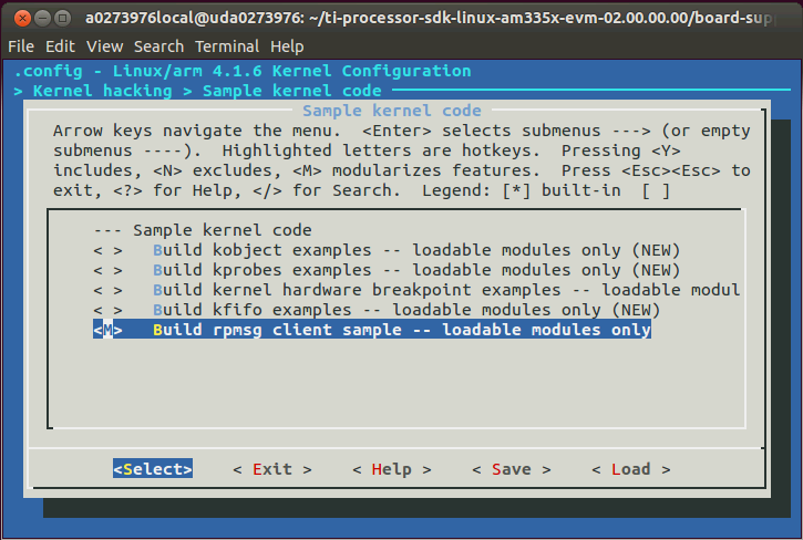
Save the config and exit menuconfig.
Build the driver: make ARCH=arm CROSS_COMPILE=arm-linux-gnueabihf-
3.5.2.1.6.4. Copy files to the target file system
At this point in the lab, we have built our two PRU firmwares as well as the new Linux driver. Now we need to get those three files into the file system of the Beaglebone Black. These next steps will show where to put each file in the file system. It is left up to the user as to how to get the files into the file system (LAB 4: Introduction to Linux driver gives instructions on how to do this with an SD card but use whatever method is most convenient in your development environment).
- Copy the PRU_RPMsg_Echo_Interrupt1.out file that we generated above to the /lib/firmware directory in your file system. Keep in mind that the .out file will be in different locations depending on whether you built with CCS (Debug or Release folder) or with the Makefile (gen folder).
- Now copy the PRU_Halt.out file (that we also generated above) to the /lib/firmware directory.
- Copy the below module from the Linux kernel tree to the
/home/root/modules directory in the file system.
- samples/rpmsg/rpmsg_client_sample.ko Now we should have the two PRU firmwares in the /lib/firmware directory as well as the kernel module in the /home/root/modules directory of the file system.
3.5.2.1.6.5. Part 1: Kernel space communication
It’s time to run the RPMsg echo example with the client sample module. This lab assumes that you are able to boot the board and navigate to the /home/root/modules directory. If you are having trouble getting to that point, LAB 4: Introduction to Linux driver gives an example on how to get there by booting with an SD card.
Use the remoteproc sysfs interface to point the remoteproc driver to the newly built firmwares for each PRU
echo 'PRU_Halt.out' > /sys/class/remoteproc/remoteproc1/firmware
echo 'PRU_RPMsg_Echo_Interrupt1.out' > /sys/class/remoteproc/remoteproc2/firmware
Once again use the remoteproc sysfs to load and the run the PRU cores
echo 'start' > /sys/class/remoteproc/remoteproc1/state
echo 'start' > /sys/class/remoteproc/remoteproc2/state
In the /home/root/modules directory of our board we should have our newly built module:
- rpmsg_client_sample.ko
In this portion of the lab we need to insert the module to kickoff the back and forth RPMsg echo sample: a. insmod rpmsg_client_sample.ko
After inserting the module, you will see the rpmsg_client_sample driver print 100 messages to the console and then exit.
If you would like to re-run the echo sample you can remove the rpmsg_client_sample driver and then insert it again:
- rmmod rpmsg_client_sample.ko
- insmod rpmsg_client_sample.ko
3.5.2.1.6.6. What just happened?
RPMsg Client Sample Module
Let’s discuss the RPMsg Client Sample module first. Open up the file /samples/rpmsg/rpmsg_client_sample.c from the Linux kernel source with a text editor. There are two methods in this file that are important for our example: rpmsg_sample_probe() and rpmsg_sample_cb().
rpmsg_sample_probe() This function gets called every time an rpmsg_channel is created with a name that matches the .name attribute of the rpmsg_driver_sample_id_table. The name that corresponds to this module, and that is in its id_table, is “rpmsg-client-sample” (remember that name, we’ll see it again soon). So, when an rpmsg_channel with the name “rpmsg-client-sample” is created, the rpmsg_sample_probe function is called with the rpmsg_channel as its only parameter. Looking at the rest of the probe function in the source code we can see that our module allocates some memory for idata and then uses rpmsg_send() to send a hello world message to the processor on the other end of the recently opened channel. In our example, the processor at the other end of the channel is PRU1.
rpmsg_sample_cb() This callback function occurs each time a new message is received at the ARM core on the rpmsg_channel. In our example, when PRU1 sends a message through the rpmsg_channel this function is called on the ARM side. In the source code we can see that the kernel module increments its message count, checks to see if it has reached the message limit (100 messages), and if it has not reached the limit it sends another hello world message. This RPMsg Client Sample shows everything necessary to create a kernel module that can communicate with a PRU core through RPMsg. However, this module does not expose an interface to Linux user space applications so its usefulness is limited.
PRU RPMsg Echo Firmware
Now let’s look at the lab_5/solution/PRU_RPMsg_Echo_Interrupt1/main.c file in a text editor. At the top of the file notice the CHAN_NAME definition: “rpmsg-client-sample”. This is the same name that we pointed out above in the RPMsg Client Sample driver and this is how we ensure that our firmware probes that kernel module. The comments are fairly descriptive in the source code but I’ll point out a few things here in the main() method:
- An RPMsg channel is created using the pru_rpmsg_channel function. This is where we use the CHAN_NAME definition that matches our sample client module
- After an interrupt is received (and we do the necessary checks to ensure that the interrupt corresponds to a message receive event) then we use the pru_rpmsg_receive function to receive the message from the other end of the channel
- In this example we are simply echoing whatever message we received back to the sender. So we use the rpmsg_pru_send function and swap the src and dst values and send the message back.
PRU Halt Firmware
This firmware is used to generate a valid firmware image for PRU0 in our example. We need to have a firmware that contains a resource_table section to be loaded into both PRU cores or else the pruss_remoteproc module will give us errors when we insert it. Since we did not need PRU0 to do anything in our example we just loaded it with a firmware that only has one instruction in the main method: __halt().
Putting It together
Both of our firmwares that we built were loaded into the PRU cores and the cores were ran. After this, but before inserting the client sample module, PRU0 halted itself and PRU1 created its side of an RPMsg channel with the name “rpmsg-client-sample”, and then began waiting for messages to arrive. After we inserted the rpmsg_client_sample module, the RPMsg channel creation was completed and a source and destination were assigned to both sides (the PRU chooses its source address with CHAN_PORT and the ARM address is assigned by the RPMsg Linux driver). Since an RPMsg channel was created with our special name the rpmsg_client_sample module’s probe() function was called which started off a chain of 100 messages back and forth between the Linux kernel on the ARM and PRU1.
3.5.2.1.6.7. Part 2: User Space Communication
- We are now going to make a very small modification to our PRU echo
firmware which will allow it to create an RPMsg channel with a different
Linux module (rpmsg_pru.ko) that exposes a character device interface
to user space.
- Change the CHAN_NAME definition in lab_5/solution/PRU_RPMsg_Echo_Interrupt1/main.c from “rpmsg-client-sample” to “rpmsg-pru”
- Rebuild the firmware using either CCS or the Makefile using the steps given above
- Copy the firmware to the /lib/firmware directory in your board’s file system
- Make sure that the firmware attribute in the remoteproc sysfs interface still points to the newly copied PRU_RPMsg_Echo_Interrupt1.out firmware (command given above)
- If you haven’t rebooted your board, remove the rpmsg_client_sample
module
- rmmod rpmsg_client_sample.ko (will not be used in this part of the example)
- Use the remoteproc sysfs interface to reload PRU1
- echo ‘stop’ > /sys/class/remoteproc/remoteproc2/state
- echo ‘start’ > /sys/class/remoteproc/remoteproc2/state
- Check to make sure a character device was created for our RPMsg
channel
- ls /dev/ | grep pru
- There should be a character device named rpmsg_pru31 (since 31 was the CHAN_PORT in the PRU firmware)
- You can ‘echo’ and ‘cat’ the rpmsg_pru31 device file
- echo “Hello” > /dev/rpmsg_pru31
- echo “World” > /dev/rpmsg_pru31
- cat /dev/rpmsg_pru31 (you will need to type Ctrl+c after this command because of the way the read works)
- You should see ‘Hello’ and ‘World’ echoed back to you on separate lines
What just happened?
PRU RPMsg Echo Firmware
We changed the CHAN_NAME of our PRU firmware and then reloaded it. This channel name change causes our channel to connect to, and then probe, a completely different Linux kernel module. In this case, rpmsg_pru.ko.
PRU Halt Firmware
This firmware remained unchanged and just halts PRU0 once it has been loaded.
RPMsg PRU Module
Now we’ll take a look at the RPMsg PRU module. Open up the file /drivers/rpmsg/rpmsg_pru.c from the Linux kernel source with a text editor. Note the .name attribute in the id_table is “rpmsg-pru” which matches our newly re-built PRU1 firmware CHAN_NAME definition. You can study the module source in depth if you’d like but the gist of it is that this module implements both the RPMsg functions necessary for communication between the PRU and the kernel as well as the functions needed to expose a character device file interface from the kernel to user space. Once the RPMsg channel is created the probe function will be called which creates the character device and places the device file in the /dev/ directory with the name rpmsg_pruX where X is the channel address of the PRU specified by the CHAN_PORT definition in the PRU firmware.
Putting It together
When we write to the character device file in the /dev/ directory (echo “Hello” > /dev/rpmsg_pru31) the rpmsg_pru_write function is called which takes our message and sends it over RPMsg to the PRU core. When the PRU core echoes the message back, the rpmsg_pru_cb function is called which stores the message in a fifo in the kernel. When we read from the character device file in the /dev/ directory (cat /dev/rpmsg_pru31) the rpmsg_pru_read function is called which pulls messages from the kernel fifo and passes them to user space.
3.5.2.1.6.8. Part 3: User Space Application
Instead of using echo and cat to read and write our file from the command line, let’s use a C program running in user space to pass messages back and forth with the PRU through the character device interface.
Copy the rpmsg_pru_user_space_echo.c file from the labs/lab_5 directory to the home directory of your Beaglebone Black board
Check to make sure your ‘/dev/rpmsg_pru31’ character device exists and is ready for communication. If not you need to load and start PRU1 using the firmware from Part 2 above.
echo 'PRU_RPMsg_Echo_Interrupt1.out' > /sys/class/remoteproc/remoteproc2/firmware
echo 'start' > /sys/class/remoteproc/remoteproc2/state
Compile the C program using gcc on the A8
gcc rpmsg_pru_user_space_echo.c -o rpmsg_pru_user_space_echo.out
Run the newly compiled user space application
./rpmsg_pru_user_space_echo.out
At this point you should see 100 messages being passed back and forth between the application and PRU1 before the program exits. This program is meant to mimic the earlier echo example that was running from kernel space. This example accomplishes the same thing from a user space application using the character device interface exposed by the rpmsg_pru.ko module.
3.5.2.1.6.9. What just happened?
rpmsg_pru_user_space_echo.c
Open the provided C file with a text editor and take a look at its contents. We open the character device file with read and write permissions (if it exists) and then we send a ‘hello world!’ message to the PRU. We then use the poll interface of the character device to wait on a response from the PRU. Once a response is received we print it to the console. We do this for 100 message and exit the program. Putting It together
We use CHAN_NAME “rpmsg-pru” in our PRU firmware in order to connect with the module that exposes the character device interface at /dev/rpmsg_pru31. We then open, read, write, and close that character device file using our user space C application. The written messages are sent down to the PRU core, the PRU core echoes the message back, and then the message is read back at the C program. This is an arbitrary example but this setup can be modified to enable any number of use cases that call for PRU<->Linux user space communication. Lab 6 will expand on this slightly and show a use case where the blinking of LEDs can be controlled from user space messages sent to a PRU core.
3.5.2.1.7. LAB 6: Blinking LEDs with RPMsg from Linux User Space
Objective
This lab will shows a PRU firmware that can parse an RPMsg message from Linux user space and toggle LEDs accordingly. Part 1 will use the echo command from the Linux command line to send a message containing which LEDs to toggle through RPMsg to PRU0. Part 2 will use a shell script to ask the user which LED(s) should be toggled and then sends the response to PRU0 through RPMsg. It is expected that you have completed and understand LAB 4: Introduction to Linux driver and LAB 5: RPMsg Communication between ARM and PRU before beginning this lab.
3.5.2.1.7.1. Build the PRU Firmware - Using CCSv6
Launch CCSv6 and select the default Workspace
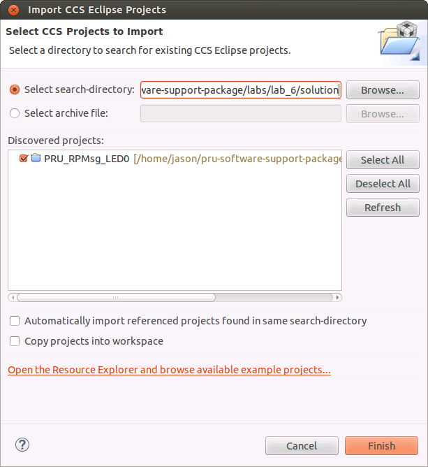
Import the PRU_RPMsg_LED0 project from the lab_6 solution folder
Project->Import CCS Projects...
Click Browse...
Navigate to <PRU_SW_PATH>/labs/lab_6/solution and click OK (where <PRU_SW_PATH> is the path to your PRU Software Support Package installation)
Click the checkbox next to the project in order to select it and then click Finish (you do not need to check ‘Automatically import referenced projects...’ or ‘Copy project into workspace’)
Make sure that the compiler include options for the project point to the include folder provided with the software package
Right-click on the project in the Project Explorer and then click Properties
Expand Build then expand PRU Compiler and then click on Include Options
Make sure that ”../../../../../include” is there as an include path
Also make sure that ”../../../../../include/am335x” is there as an include path
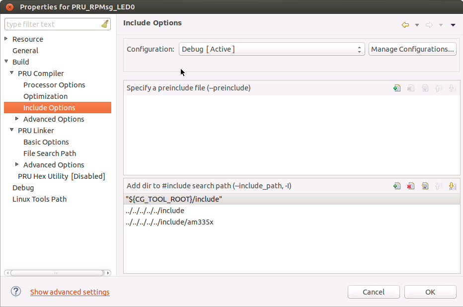
Click OK
Make sure that the rpmsg_lib library is added in the project
Right-click on PRU_RPMsg_LED0 in the Project Explorer and then click Properties
Expand Build then expand PRU Linker and then click on File Search Path
Make sure that ”../../../../../lib/rpmsg_lib.lib” is there as an included library file
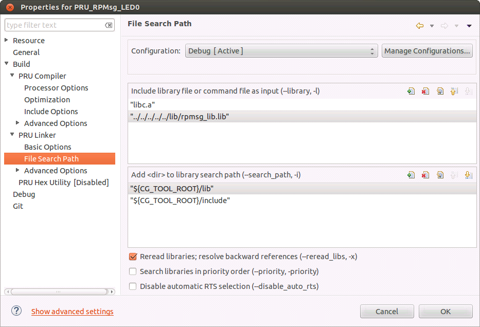
Click OK
Build the project and make sure there are no errors
- Right-click on the project in the Project Explorer and then click Rebuild Project
3.5.2.1.7.2. Build the PRU Firmware - Using the Provided Makefile
- Open a command prompt or terminal window
- Set the PRU_CGT environment variable to point to the PRU code
generation tools folder. This folder is included in the Linux Processor
SDK v2.0.2.11 and newer.
- Linux: export PRU_CGT=<path_to_Linux_proc_sdk>/linux-devkit/sysroots/x86_64-arago-linux/usr/share/ti/cgt-pru
- Windows: set PRU_CGT=C:/TI/ccs_v6_0_1/ccsv6/tools/compiler/ti-cgt-pru_2.1.0
- Change to the PRU_RPMsg_LED0 directory
- cd <PRU_SW_PATH>/labs/lab_6/solution/PRU_RPMsg_LED0
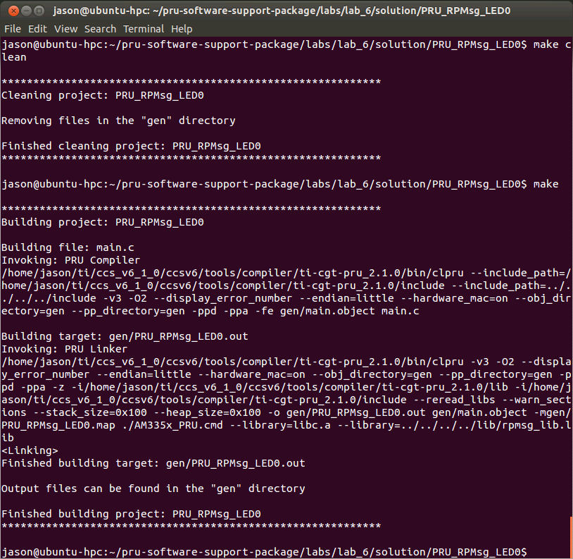
- Clean the previously generated files if they exist.
- make clean
- Build the project.
make
The output for the project should be similar to the below screen shot:
3.5.2.1.7.3. Copy files to the target file system
Now we need to move our built files to the file system on the board.
- Copy the PRU_RPMsg_LED0.out file that we generated above to the /lib/firmware directory in your file system. Keep in mind that the .out file will be in different locations depending on whether you built with CCS (Debug or Release folder) or with the Makefile (gen folder).
- Now copy the PRU_Halt.out file (that we generated in LAB 5: RPMsg Communication between ARM and PRU) to the /lib/firmware directory. Now we should have the two PRU firmwares in the /lib/firmware directory.
3.5.2.1.7.4. Part 1: Linux Command Line LED Toggling
This lab assumes that the Linux device tree modifications have been made to allow PRU0 to control the LEDs on the PRU cape. See LAB 4: Introduction to Linux driver.
- The modules necessary for this lab are included in the default Linux configuration of the Linux Processor SDK.
- After the board finishes booting you need to use the remoteproc sysfs
interface to point the driver to the correct firmwares and then load and
run them.
- echo ‘PRU_RPMsg_LED0.out’ > /sys/class/remoteproc/remoteproc1/firmware
- echo ‘PRU_Halt.out’ > /sys/class/remoteproc/remoteproc2/firmware
- echo ‘start’ > /sys/class/remoteproc/remoteproc1/state
- echo ‘start’ > /sys/class/remoteproc/remoteproc2/state
- Check to make sure the RPMsg PRU character device has been created
- ls /dev/ | grep pru
- You should see rpmsg_pru30 in the list of devices (because 30 is the CHAN_PORT we used in the PRU_PRMsg_LED0 firmware)
- Send an RPMsg message from the Linux command line to turn on the Red
(‘r’ or ‘R’), Blue (‘b’ or ‘B’), Orange (‘o’ or ‘O’), or Green (‘g’ or
‘G’) LED on the PRU cape
- echo “r” > /dev/rpmsg_pru30
- echo “G” > /dev/rpmsg_pru30
- echo “rgbo” > /dev/rpmsg_pru30
Each time you echo a string into the PRU, you should see the corresponding LEDs toggle on the PRU cape.
3.5.2.1.7.5. What just happened?
PRU_RPMsg_LED0
Open the main.c file provided in the labs/lab_6/solution/PRU_RPMsg_LED0 folder in a text editor. Notice that CHAN_NAME is “rpmsg-pru” which matches our Linux driver at drivers/rpmsg/rpmsg_pru.c. Also notice that CHAN_PORT is 30 in this example which creates a character device at /dev/rpmsg_pru30. Once a message is received its payload is iterated through looking for any of our LED characters (‘rgboRGBO’) and if one is found that LED color is toggled using register R30. If there were other tasks that the PRU firmware needed to handle, outside of receiving messages, then using interrupts to check for new messages would be faster. Interrupt based and polling based RPMsg examples are provided for each PRU core in the examples folder of the PRU Software Support Package.
Putting It together
This example once again connects the PRU firmware with Linux user space using the rpmsg_pru.ko module. As you write to the character device file (using the echo commands) the messages are passed to PRU0 where they are parsed looking for the LED colors to toggle. When a character that corresponds to a color is found by PRU0, that LED is toggled on the PRU cape.
3.5.2.1.7.6. Part 2: Linux Shell Script LED Toggling
This lab assumes that you have just completed Part 1 above and the rpmsg_pru30 character device still exists and the PRU_RPMsg_LED0 firmware is still loaded into PRU0.
- Copy the pru0_led.sh file from the labs/lab_6/ folder into the file system of your board
- On the board, navigate to the directory where you just copied the
script and execute it
- ./pru0_led.sh (If it does not execute, try giving it execute permissions: chmod +x pru0_led.sh)
- You should get a prompt at the command line asking you to enter a color to toggle. Follow the directions and the LEDs on the PRU cape should light up and turn off. Type ‘q’ to quit the script and return to the command line.
3.5.2.1.7.7. What just happened?
pru0_led.sh
Open the pru0_led.sh script found in the /labs/lab_6/ folder in a text editor. This is a very simple script that asks for user input and then passes it down to PRU0 by using the echo command and the character device file.