3.4.2.3. RPMsg Quick Start Guide
3.4.2.3.1. Introduction
RPMsg is a method of passing messages and data between the PRU cores and the ARM core running Linux. RPMsg is enabled by a combination of remoteproc and the virtio framework. For more information about remoteproc, reference RemoteProc. For more information abour RPMsg, reference RPMsg.
This Quick Start Guide will walk you through every step necessary to run your first RPMsg example, from downloading the Linux Processor SDK, all the way up to communicating with the PRUs from user space.
If you are familiar with the Linux Processor SDK from Texas Instruments then portions of this guide will seem elementary or possibly redundant. If this is the case, feel free to skip over the early sections and get directly to the RPMsg parts. The intent of this guide is to provide a single straight through process to run an RPMsg example and then show where to modify and rebuild code in order to start PRU/RPMsg development.
If you have any questions or corrections while going through this guide please post them on the E2E Forum here.
3.4.2.3.1.1. Supported Devices
Linux ARM to PRU RPMsg communication is supported on these processors:
- AM335x
- AM437x
- AM572x
- AM65x
- AM64x
3.4.2.3.1.2. Hardware Assumptions
The below hardware assumptions have been made while writing this guide:
- The reader has a host computer running Ubuntu Linux (Ubuntu version 14.04 was used while writing this document)
- The reader has a TI EVM with with a micro SD card and the cables necessary for Linux console output
3.4.2.3.2. Getting the Linux Processor SDK
The first step is to download and install the Linux Processor SDK onto your host computer that is running Ubuntu Linux.
Download the SDK that corresponds to the evaluation board that you have
- Linux Processor SDK for AM335x
- Linux Processor SDK for AM437x
- Linux Processor SDK for AM572x
- Linux Processor SDK for AM65x
- Linux Processor SDK for K2G
You only need to download the ti-processor-sdk-linux-<DEV>-evm-<VERSION>-Linux-x86-Install.bin file from this page
Navigate to the newly downloaded bin file and make it executable
- cd path/to/downloaded/SDK/bin/file/
- chmod +x ti-processor-sdk-linux-<DEV>-evm-<VERSION>-Linux-x86-Install.bin
Launch the installer
- ./ti-processor-sdk-linux-<DEV>-evm-<VERSION>-Linux-x86-Install.bin
Follow the steps in the installer to complete the installation
- The remainder of this guide assumes that the default installation directory was selected - /home/user/ti-processor-sdk-linux-<DEV>-evm-<VERSION>/
You now have the Linux Processor SDK installed on your Linux host computer. This version of the SDK includes the PRU Software Support Package in the ‘example-applications/pru-icss-x.y.z’ folder. This software support package includes examples, libraries, and PRU Hands-on Labs to help you get started with your PRU development process. This guide will use one of the PRU RPMsg examples included in that software support package.
3.4.2.3.3. Configuring and Building the Linux Kernel with RPMsg Support
The Linux kernel config that ships with this version of the Linux Processor SDK already has RPMsg module support enabled. The rest of this section is to show how/where to enable/disable the modules using menuconfig and how to rebuild the modules and kernel if you would like to make any changes to the modules, kernel, or device tree.
In the interest of simplicity, this guide will follow the full procedure found in the Linux SDK Kernel Users Guide even though some of these steps may not be absolutely necessary for our purposes.
Navigate to the Linux kernel source directory in the Linux Processor SDK that we previously installed (this guide assumes the default installation directory was chosen)
- cd /home/user/ti-processor-sdk-linux-<DEV>-evm-<VERSION>/board-support/linux-x.x.x+gitAUTOINC+YYY-ZZZ/
Place the cross-compiler toolchain in your PATH environment variable
export PATH=/home/user/ti-processor-sdk-linux-<DEV>-evm-<VERSION>/linux-devkit/sysroots/x86_64-arago-linux/usr/bin:$PATH
Clean the kernel sources
- make ARCH=arm CROSS_COMPILE=arm-linux-gnueabihf- distclean
Set the kernel configuration to the default configuration included in the Processor SDK for the device you are using
- make ARCH=arm CROSS_COMPILE=arm-linux-gnueabihf- tisdk_<DEV>-evm_defconfig
Enable RPMsg support using menuconfig
make ARCH=arm CROSS_COMPILE=arm-linux-gnueabihf- menuconfig
Type ‘m’ next to the following two configurations to build them as kernel modules (beginning with Linux Processor SDK v02.00.02.11 these modules will be enabled by default)
- Device Drivers > Remoteproc Drivers > TI PRUSS remoteproc support
- Device Drivers > Rpmsg drivers > PRU RPMsg Communication driver
If you type ‘y’ instead of ‘m’ next to these modules then your board will pause for a long time during the boot procedure and the PRU loading process will fail
Save the configuration and exit menuconfig
Build the Linux kernel
- make ARCH=arm CROSS_COMPILE=arm-linux-gnueabihf- zImage
Build the device tree binary file
- make ARCH=arm CROSS_COMPILE=arm-linux-gnueabihf- am335x-boneblack.dtb
Example .dtb name given above is for the BeagleBone Black. To find the .dtb name for a different board use the list found at :ref:`kernel_users_guide_compiling_the_device_tree_binaries`.
Build the modules
- make ARCH=arm CROSS_COMPILE=arm-linux-gnueabihf- modules
3.4.2.3.4. Creating a Bootable SD Card with RPMsg Support
This section of the guide will walk you through using a script that is included in the Linux Processor SDK. This script will format your micro SD card and load the default images for the Linux kernel, device tree, and filesystem. Once we’ve created the default SD card we will overwrite the kernel, device tree, and modules with the newly built versions from the previous section of this guide. At the end of this section we will have a bootable SD card (that includes RPMsg support) that we can plug into a board, turn on power, and get to a Linux login prompt.
Plug your micro SD card into your Ubuntu host computer
- If your computer doesn’t have an SD card reader you will need a USB card reader
Change to the ‘bin’ directory in the Processor SDK
- cd /home/user/ti-processor-sdk-linux-<DEV>-evm-<VERSION>/bin/
Run the SD card creation script with sudo rights and enter your password when prompted
- sudo ./create-sdcard.sh
Select the SD card from the list the script provides
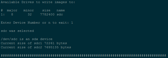
Select that you would like to partition the drive with 2 partitions
Once partitioning is completed select ‘y’ and continue with installing the filesystem
Now choose ‘1’ to install the pre-built images from the SDK
At this point, we’ve used the SD card creation script to make a bootable SD card with the default, out-of-box, Linux kernel and filesystem as it ships in the Processor SDK. Now we just need to replace the kernel, device tree, and modules on the SD card with the ones that we rebuilt in the previous section. Let’s do that now.
The SD card creation script unmounts the SD card when it finishes. Unplug the SD card and then plug it back into your computer to re-mount it. In Ubuntu 14.04 the card auto-mounts the two partitions to the /media/user/boot/ and /media/user/rootfs/ directories.
The kernel and device tree file that the board will use to boot is located in the /media/user/rootfs/boot/ directory. If you check that directory now you will see that it is filled with default kernels, default device trees, and symbolic links. To make this guide simple and to also show that we are in fact booting our newly built kernel and device tree, let’s delete everything in this boot directory
- sudo rm /media/user/rootfs/boot/*
Navigate to the Linux kernel source directory
- cd /home/user/ti-processor-sdk-linux-<DEV>-evm-<VERSION>/board-support/linux-x.y.z+gitAUTOINC+YYY-ZZZ/
Copy the new kernel to the SD card
- sudo cp arch/arm/boot/zImage /media/user/rootfs/boot/
Copy the new device tree binary to the SD card
- sudo cp arch/arm/boot/dts/am335x-boneblack.dtb /media/user/rootfs/boot/
Once again the example .dtb given above is for the BeagleBone Black. Check :ref:`kernel_users_guide_compiling_the_device_tree_binaries` and use the corresponding name if you are using a different board.
Install the newly built modules onto the SD card filesystem
- sudo make ARCH=arm INSTALL_MOD_PATH=/media/user/rootfs/ modules_install
Synchronize the data on the disk with the memory to make sure all of the files have completed copying over to the SD card
- sync
Unmount the two SD card partitions from your Ubuntu host computer
- sudo umount -f /media/user/rootfs
- sudo umount -f /media/user/boot
3.4.2.3.5. Booting the Board and Testing RPMsg
Make sure your board is set up to boot from the SD card
If your board is not set up to boot from the SD card, follow the instructions on the bottom of this page Board is Not Set Up for SD Card Boot
Plug the SD card from the previous step into your evaluation board
Plug the serial cable from your evaluation board into your Ubuntu host computer
- Reference your evaluation board getting started guide to determine which cable you will need and where you will need to plug it into the evaluation board
- In the case of the BeagleBone Black you will need an FTDI to TTL cable like the one found here
Find out which tty device on your Ubuntu host computer corresponds to your evaluation board
- ls /dev/ | grep ttyUSB*
Depending on the evaluation board you may need to power the board up before the ttyUSBn device shows up on your Ubuntu computer
Use your favorite terminal emulator to connect to your evaluation board (in the example given below I use picocom and my device is on /dev/ttyUSB0)
- sudo picocom -b 115200 /dev/ttyUSB0
Power up your evaluation board
- Power up method (button press, power source, etc.) will also vary based on which board you are using
Wait for the board to complete booting and arrive at the ‘<DEV>-evm login:’ prompt and type ‘root’ to login as root
- <DEV>-evm login: root
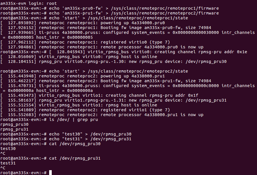
Use the remoteproc sysfs interface to specify the firmware name to boot and to start the PRU cores
- echo ‘am335x-pru0-fw’ > /sys/class/remoteproc/remoteproc1/firmware
- echo ‘am335x-pru1-fw’ > /sys/class/remoteproc/remoteproc2/firmware
- echo ‘start’ > /sys/class/remoteproc/remoteproc1/state
- echo ‘start’ > /sys/class/remoteproc/remoteproc2/state
List all of the devices under /dev/ and look for the two rpmsg_pru character devices
- ls /dev/
or
- ls /dev/ | grep pru
Write to each of the character devices to test them out
- echo “test30” > /dev/rpmsg_pru30
- echo “test31” > /dev/rpmsg_pru31
Now read from each of the character devices to make sure that the PRUs echoed the test strings back
- cat /dev/rpmsg_pru30
You will need to press ‘Ctrl + c’ to stop reading and close the character device
- cat /dev/rpmsg_pru31
You will need to press ‘Ctrl + c’ to stop reading and close the character device
3.4.2.3.5.1. Out of Box Demo Explanation
The Linux Processor SDK comes with demo PRU firmwares loaded in the filesystem. These PRU firmwares echo all received RPMsgs directly back to the sender. That’s why when we write to the rpmsg_pru character device in the section above, we can then read the exact same message back from the same rpmsg_pru character device. The written message was actually delivered to the PRU as an RPMsg and then a second RPMsg was generated by the PRU (with the same payload) and sent back to the ARM on the same RPMsg channel/character device that sent the original message. The source code for these demo PRU projects can be found in the SDK’s example-applications/pru-icss-x.y.z/examples/<DEV>/ folder under PRU_RPMsg_Echo_Interruptn. The next section will teach you how to rebuild those demo firmwares from source, place the generated binary in the embedded file system, and then reload and re-run the PRUs with the newly built firmware.
3.4.2.3.6. Getting Started with RPMsg Development
3.4.2.3.6.1. Rebuilding the PRU Firmwares from Source
The source code for the PRU firmwares that are used in this out-of-box demo can be found in the Linux Processor SDK in the ‘example-applications/pru-icss-x.y.z/examples/’ folder:
- Examples Used
- /home/user/ti-processor-sdk-linux-<DEV>-evm-<VERSION>/example-applications/pru-icss-x.y.z/examples/<DEV>/PRU_RPMsg_Echo_InterruptN (or PRU_RPMsg_Echo_InterruptM_N if there are 4 PRUs in the device)
To rebuild the firmwares from source code use the Makefile provided in each folder:
- Navigate to the directory of the example that you want to rebuild
- cd /home/user/ti-processor-sdk-linux-<DEV>-evm-<VERSION>/example-applications/pru-icss-x.y.z/examples/<DEV>/PRU_RPMsg_Echo_InterruptN
- Export the location of the PRU Code Generation Tools that are
provided in the Linux Processor SDK
- export PRU_CGT=/home/user/ti-processor-sdk-linux-<DEV>-evm-<VERSION>/linux-devkit/sysroots/x86_64-arago-linux/usr/share/ti/cgt-pru
- Clean the directory
- make clean
- Rebuild the project and generate the .out file in the ‘gen’ directory
- make
- Move to the ‘gen’ directory in the project folder to see the
generated .out file
- cd gen/
- ls
3.4.2.3.6.2. Placing the Rebuilt Firmware into the Embedded Linux File System
The pruss_remoteproc module is responsible for loading the PRU firmwares and resetting the PRUs. This module expects to find the PRU firmwares in the device file system at the following locations. The name of the firmware to be loaded is specified using the sysfs interace mentioned earlier.
Out of the box, the file system provided in the Linux Processor SDK has symbolic links in the /lib/firmware directory that point to the RPMsg examples in the /lib/firmware/pru directory. In order to get the PRUs to use your newly built firmware you will need to take the .out file from the ‘gen/’ directory and:
rename it to be one of the firmware names above and place it in the /lib/firmware/ directory
- E.g. rename PRU_RPMsg_Echo_Interrupt0.out to am335x-pru0-fw and place it in the /lib/firmware/ directory
or
place the .out file anywhere in the embedded Linux filesystem and then create a symbolic link matching the firmware name above that points to the .out file
- E.g. place PRU_RPMsg_Echo_Interrupt0.out in the /lib/firmware/pru/ directory and then make sure the /lib/firmware/am335x-pru0-fw symbolic link points to that file
Note
In the latest version of the Linux Processor SDK it is possible to use the remoteproc sysfs interface to specify the name of the firmware you would like to load from the /lib/firmware/ directory. Please see see LAB 5: RPMsg Communication between ARM and PRU in the PRU Hands-on Labs for an example of this method. So, the am335x-pru0-fw name being used on this page isn’t absolutely necessary, but for legacy reasons is being shown here.
3.4.2.3.6.3. Loading the New Code into the PRUs and Running
The PRUs must be stopped before loading new firmware code into them. In order to stop the PRUs, either reset your board, or use the below code to stop the PRUs through the sysfs interface.
echo 'stop' > /sys/class/remoteproc/remoteproc1/state
echo 'stop' > /sys/class/remoteproc/remoteproc2/state
Use the remoteproc sysfs interface to point the remoteproc driver to the newly built firmwares for each PRU.
echo 'am335x-pru0-fw' > /sys/class/remoteproc/remoteproc1/firmware
echo 'am335x-pru1-fw' > /sys/class/remoteproc/remoteproc2/firmware
Finally, use the remoteproc sysfs to load and the run the PRU cores.
echo 'start' > /sys/class/remoteproc/remoteproc1/state
echo 'start' > /sys/class/remoteproc/remoteproc2/state
For a more detailed explanation on the internals of the PRU firmwares being used as well as how to start making modifications for your specific use case, please see LAB 5: RPMsg Communication between ARM and PRU and LAB 6: Blinking LEDs with RPMsg from Linux User Space in the PRU Hands-on Labs
3.4.2.3.7. Common Issues
3.4.2.3.7.1. Board is Not Set Up for SD Card Boot
This guide shows the SD card boot method where the evaluation device expects to find the kernel (zImage), device tree binary (.dtb file), and file system all on the SD card. If that is not the case on your evaluation board, this section will walk you through the U-Boot changes necessary to make your board use SD card boot.
Open a serial port connection to your device from your Ubuntu host computer
- sudo picocom -b 115200 /dev/ttyUSB0
Power up your evaluation board and press Enter when prompted to ‘Hit any key to stop autoboot: 1’. This will stop the boot process at the U-Boot prompt
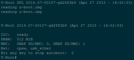
Reset the U-Boot environment variables to the default settings
- env default -f -a
Save the default settings
- saveenv
Set the ip_method to none
- setenv ip_method none
Set the name of the bootfile to zImage
- setenv bootfile zImage
Set the getuenv environment variable
- setenv getuenv ‘if mmc rescan; then if run loadbootenv; then run importbootenv; fi; fi;’
Set the boot command
- setenv bootcmd ‘mmc rescan; run findfdt; run getuenv; run loadimage; run loadfdt; run mmcargs; bootz ${loadaddr} - ${fdtaddr}’
Save the new environment variables
- saveenv
Use the new environment variables to boot from the SD card
- boot