3.5.5.2. PRU Cape Hardware User Guide
3.5.5.2.1. Introduction
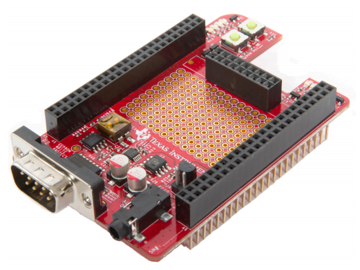
This document describes the hardware architecture of the PRU Cape which is compatible with the Beagle Bone Black development platform.
3.5.5.2.1.1. Description
The PRU Cape is a test, development, and evaluation module system that enables developers to write software and develop hardware around the PRU subsystem. Examples of basic I/O such as push buttons and LEDs as well as more complicated examples such as audio and 1-Wire for temperature sensing are available on this cape to showcase what the PRU can accomplish in terms of inputs and outputs.
The following sections give more details regarding the PRU Cape.
3.5.5.2.2. Schematics/Design/Errata Files
Design Files (located under Technical Documents), includes:
- Schematic
- Layout
- Assembly Drawings
- CAD Files
- Bill of Materials (BOM)
Errata
I2C SCL and SDA signals swapped (REV 1.2A)
The AM335x I2C2_SDA signal (routed to BBB Header P9-20) is connected to the EEPROM SCL pin. The AM335x I2C2_SCL signal (routed to BBB Header P9-19) is connected to the EEPROM SDA pin. The EEPROM is blank, and if it is to be used, the cape needs to be modified to physically swap the SDA and SCL signals.
PRU Cape Getting Started Guide
3.5.5.2.3. System Description
3.5.5.2.3.1. System Board Diagram
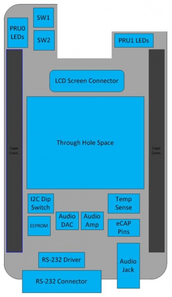
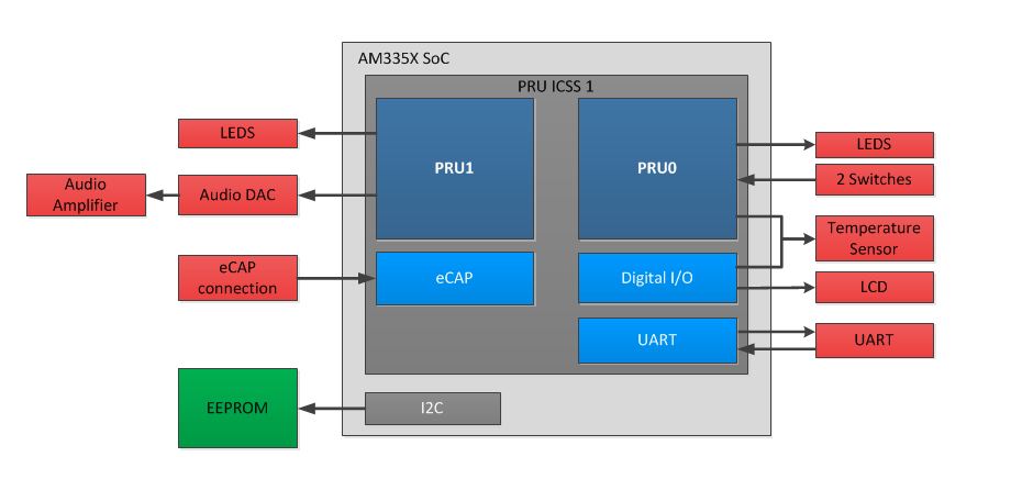
The system block diagram of the PRU Cape are shown in the below Figures.
PRU Cape Board Layout:
PRU Cape Functional Block Diagram
3.5.5.2.3.2. Signals Used
| CAPE NAME | BBB HEADER NUMBER | BBB MODE 0 NAME | CAPE USE |
| PR1_PRU0_GPO0 | P9-31 | MCASP0_ACLKX | PRU0 Blue LED |
| PR1_PRU0_GPO1 | P9-29 | MCASP0_FSX | PRU0 Green LED |
| PR1_PRU0_GPO2 | P9-30 | MCASP0_AXR0 | PRU0 Orange LED |
| PR1_PRU0_GPO3 | P9-28 | MCASP0_AHCLKR | PRU0 Red LED |
| PR1_PRU1_GPO3 | P8-44 | LCD_DATA3 | PRU1 Blue LED |
| PR1_PRU1_GPO4 | P8-41 | LCD_DATA4 | PRU1 Green LED |
| PR1_PRU1_GPO5 | P8-42 | LCD_DATA5 | PRU1 Red LED |
| PR1_PRU0_GPI7 | P9-27 | GPIO3_19 | SW1 |
| PR1_PRU0_GPI5 | P9-25 | GPIO3_21 | SW2 |
| PR1_PRU1_GPO0 | P8-45 | LCD_DATA0 | Audio Data |
| PR1_PRU1_GPO1 | P8-46 | LCD_DATA1 | Audio Clock |
| PR1_PRU1_GPO2 | P8-43 | LCD_DATA2 | Audio Sync |
| PR1_UART0_TXD | P9-24 | UART1_TXD | UART TxD |
| PR1_UART0_RXD | P9-26 | UART1_RXD | UART RxD |
| PR1_UART0_RTS | P9-21 | UART2_TXD | UART RTS |
| PR1_UART0_CTS | P9-22 | UART2_RXD | UART CTS |
| PR1_PRU_EDIO_DATA_OUT6 | P8-39 | LCD_DATA6 | LCD RS |
| PR1_PRU_EDIO_DATA_OUT4 | P8-28 | LCD_PCLK | LCD E |
| PR1_PRU_EDIO_DATA_OUT0 | P9-18 | I2C1_SDA | LCD Data4 |
| PR1_PRU_EDIO_DATA_OUT1 | P9-17 | I2C1_SCL | LCD Data5 |
| PR1_PRU_EDIO_DATA_OUT2 | P8-27 | LCD_VSYNC | LCD Data6 |
| PR1_PRU_EDIO_DATA_OUT3 | P8-29 | LCD_HSYNC | LCD Data7 |
| PR1_PRU_EDIO_DATA_OUT5 | P8-30 | LCD_DE | HDQ input |
| PR1_PRU0_GPI14 | P8-16 | GPIO1_14 | HDQ output |
| I2C2_SDA | P9-20 | I2C2_SDA | I2C SCL |
| I2C2_SCL | P9-19 | I2C2_SCL | I2C SDA |
| PR1_ECAP0_IN_PWM0_OUT | P9-42 | ECAP0_IN_PWM0_OUT | ECAP0_IN_PWM0_OUT |
| PR1_PRU0_GPI15 | P8-15 | GPMC_AD15 | PRU0_GPI_15 |
| VDD_3V3C | P9-3, P9-4 | VDD_3V3C | VDD_3V3C |
| DGND | P8-1, P8-2, P9-1,P9-2 | DGND | DGND |
| DGND | P9-43, P9-44, P9-45, P9-46 | DGND | DGND |
Table: Table 1. Signals Used
3.5.5.2.4. PRU Cape Functional Block Descriptions
This section describes major functional blocks of the PRU Cape.
3.5.5.2.4.1. Audio
The audio portion of the PRU Cape is composed of a Dual 8-bit DAC (DAC082S085) and a dual 105 mW Amplifier (LM4808). The output is then sent to a 3.5 mm Audio jack with a max pk-pk of .89V, following the consumer standard.
| CAPE NAME | BBB HEADER NUMBER | BBB MODE 0 NAME | CAPE USE |
| PR1_PRU1_GPO0 | P8-45 | LCD_DATA0 | Audio Data |
| PR1_PRU1_GPO1 | P8-46 | LCD_DATA1 | Audio Clock |
| PR1_PRU1_GPO2 | P8-43 | LCD_DATA2 | Audio Sync |
3.5.5.2.4.2. EEPROM
The EEPROM on the PRU cape is the CAT24C256WI-G EEPROM 256Kb I2C SOIC8, and has an attached DIP switch to manipulate the I2Caddress. The first 78 bytes hold a file that the Beagle Bone Black will read to identify the cape, the rest of the EEPROM is available for use.
| CAPE NAME | BBB HEADER NUMBER | BBB MODE 0 NAME | CAPE USE |
| I2C2_SDA | P9-20 | I2C2_SDA | I2C SCL |
| I2C2_SCL | P9-19 | I2C2_SCL | I2C SDA |
3.5.5.2.4.3. eCAP
These pins are brought out on the board that connect to the eCAP0 PWM0 IN to allow use of the PRU Subsystem’s eCAP IP.
| CAPE NAME | BBB HEADER NUMBER | BBB MODE 0 NAME | CAPE USE |
| PR1_ECAP0_IN_PWM0_OUT | P9-42 | ECAP0_IN_PWM0_OUT | ECAP0_IN_PWM0_OUT |
| PR1_PRU0_GPI15 | P8-15 | GPMC_AD15 | PRU0_GPI_15 |
3.5.5.2.4.4. LCD
The LCD screen is on a duaghter board with its own built in controller, model number NHD-0208AZ-RN-YBW-33V. The LCD is connected to the PRU Cape throught the 2x8 female header in the middle of the cape. The LCD is a 2x8 Character display operating at 3.3V.
| Cape Name | BBB Header Number | BBB Mode 0 Name | Cape Use |
| PR1_PRU_EDIO_DATA_OUT6 | P8-39 | LCD_DATA6 | LCD RS |
| PR1_PRU_EDIO_DATA_OUT4 | P8-28 | LCD_PCLK | LCD E |
| PR1_PRU_EDIO_DATA_OUT0 | P9-18 | I2C1_SDA | LCD Data4 |
| PR1_PRU_EDIO_DATA_OUT1 | P9-17 | I2C1_SCL | LCD Data5 |
| PR1_PRU_EDIO_DATA_OUT2 | P8-27 | LCD_VSYNC | LCD Data6 |
| PR1_PRU_EDIO_DATA_OUT3 | P8-29 | LCD_HSYNC | LCD Data7 |
3.5.5.2.4.5. LEDs
The PRU Cape has 7 surface mounted LEDs, including Red, Orange, Blue and Green colors. There are 4 LEDs connected to PRU0 output, and 3 connected to PRU1 output.
| CAPE NAME | BBB HEADER NUMBER | BBB MODE 0 NAME | CAPE USE |
| PR1_PRU0_GPO0 | P9-31 | MCASP0_ACLKX | PRU0 Blue LED |
| PR1_PRU0_GPO1 | P9-29 | MCASP0_FSX | PRU0 Green LED |
| PR1_PRU0_GPO2 | P9-30 | MCASP0_AXR0 | PRU0 Orange LED |
| PR1_PRU0_GPO3 | P9-28 | MCASP0_AHCLKR | PRU0 Red LED |
| PR1_PRU1_GPO3 | P8-44 | LCD_DATA3 | PRU1 Blue LED |
| PR1_PRU1_GPO4 | P8-41 | LCD_DATA4 | PRU1 Green LED |
| PR1_PRU1_GPO5 | P8-42 | LCD_DATA5 | PRU1 Red LED |
3.5.5.2.4.6. Switches
The PRU Cape has two pushbutton switches connected to PRU0 inputs.
| CAPE NAME | BBB HEADER NUMBER | BBB MODE 0 NAME | CAPE USE |
| PR1_PRU0_GPI5 | P9-27 | GPIO3_19 | SW1 |
| PR1_PRU0_GPI7 | P9-25 | GPIO3_21 | SW2 |
3.5.5.2.4.7. Temperature Sensor
The temperature sensor is a MAX31820 ambient temperature sensor, with a 1-Wire interface. Two pins are tied together from the PRU to create input and output on a single wire.
| CAPE NAME | BBB HEADER NUMBER | BBB MODE 0 NAME | CAPE USE |
| PR1_PRU_EDIO_DATA_OUT5 | P8-30 | LCD_DE | HDQ input |
| PR1_PRU0_GPI14 | P8-16 | GPIO1_14 | HDQ output |
3.5.5.2.4.8. Test Space
The test space is a set of 150 through holes (15x10). There is no connection between the through holes and is meant for attaching a through hole component, wheather it be an IC or passive to test with the PRU or any signal that can be accessed through the Cape Headers.
3.5.5.2.4.9. UART
There is one RS-232 connector (DB9 male) on the PRU Cape. The MAX3232ECD is the line driver/receiver.
| CAPE NAME | BBB HEADER NUMBER | BBB MODE 0 NAME | CAPE USE |
| PR1_UART0_TXD | P9 24 | UART1_TXD | UART TxD |
| PR1_UART0_RXD | P9 26 | UART1_RXD | UART RxD |
| PR1_UART0_RTS | P9 21 | UART2_TXD | UART RTS |
| PR1_UART0_CTS | P9 22 | UART2_RXD | UART CTS |