|
AM243x Motor Control SDK
09.01.00
|


|
|
AM243x Motor Control SDK
09.01.00
|
|
This document presents the firmware implementation details of the Tamagawa receiver protocol.
It is an encoder technology used for obtaining high-precision position information in machine tools, robotics, and so forth. Tamagawa rotary encoders consist broadly of two types: incremental or absolute. Incremental encoders provide a train of pulses, while the absolute-type provides digital values. The absolute encoder group contains the single-turn types that provide outputs which can be open collector or emitter follower. The absolute encoder types include the pure digital encoder types, which provide a digital word output through a line driver such as an RS485, or a semi-absolute encoder, which provides both digital word and pulse train outputs. Of the RS485 line-driver output absolute encoders that provide only digital output, another classification is the full absolute encoder. A full absolute encoder provides multi-turn digital data, which is known as SmartAbs, and is compatible with the Tamagawa Smartceiver AU5561N1. Another type of encoders, known as SmartInc, provide single-turn information in digital format with an RS485 line driver output. The AM64x/AM243x Tamagawa receiver implementation is equivalent to the Smartceiver AU5561N1, which can communicate with Tamagawa SmartAbs as well as SmartInc encoders.
The AM64x/AM243x Tamagawa receiver communicates with Tamagawa SmartAbs and SmartInc encoders and provides drive control with digital information to and from the encoder. Tamagawa communication is broadly classified into three types: data readout, reset, and EEPROM transactions. Four data readout transactions occur: absolute data in one revolution, multi-turn data, encoder ID, and a combination of all of these along with the encoder error status. The reset transaction always returns the absolute data in one revolution while performing different types of resets. Three types of reset are available: reset of absolute data in one revolution, reset of multi-turn data, and error reset. The EEPROM transaction allows the system to read and write to the EEPROM in the encoder. Each transaction has a unique data ID and consists of different fields, namely control, status, data, cyclic redundancy check (CRC), EEPROM address, and EEPROM data depending on the type of transaction, that is, data ID.
Each field is 10-bits long, beginning with a start bit and ending with a delimiter. The 8 bits between these start bits and delimiters depends on the field type. The control field contains the data ID information. Data, status, and CRC fields similarly contain data, status, and CRC in those 8 bits. The receiver initially sends the control field to start the communication. This action indicates the type of transaction to the encoder and the encoder returns this information based on the data ID, as the previous paragraph explains. The encoder always returns the control field back to the receiver. In the case of data readout and reset transactions, the encoder returns the control field followed by the status, data, and ending with the CRC field at the end. In the case of an EEPROM read or write, the receiver, in addition to the control field, sends the EEPROM address field (and EEPROM data field for write) followed by the CRC. The encoder returns the control field, followed by the EEPROM address, EEPROM data, and CRC fields. The physical layer communication is RS422/RS485 based.
Refer TRM for details
Refer PRU-ICSS chapter of AM64x/AM243x Technical Reference Manual
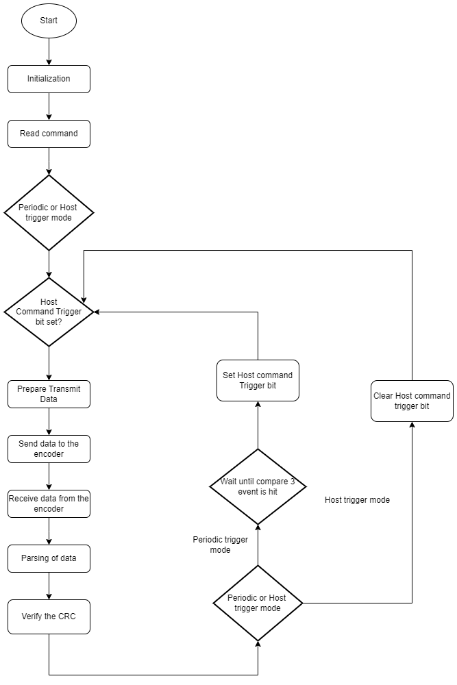
At start-up, the application running on the ARM Cortex-R5 initializes the module clocks and configures the pinmux. The PRU is initialized and the PRU firmware is loaded on PRU slice of choice for a chosen ICSS instance (tested on PRU1 on ICSSG0). After the PRU1 starts executing, the Tamagawa interface is operational and the application can use it to communicate with an encoder. Use the Tamagawa diagnostic example to learn more about initialization and communication with the Tamagawa interface. This Tamagawa diagnostic example, also provides an easy way to validate the Tamagawa transactions. The diagnostic example provides menu options on the host PC in a serial terminal application, where the user can select the data ID code to be sent. Based on the data ID code, the application updates the Tamagwa interface with the data ID code and trigger transaction. The application then waits until it receives an indication of complete transaction by the firmware through the interface before displaying the result.
The firmware first initializes the PRU hardware. Then it checks whether it is host trigger mode or periodic trigger mode. In host trigger mode, it waits until a command has been triggered through the interface. In periodic trigger mode, the firmware sets host trigger bit based on compare 3 event configured. Upon triggering the transmit data is set up based on the data ID code and the data is transmitted. The data ID code then waits until receiving all the data that depends on the data ID. The parsing over the received data then commences, which is again based on the data ID, and the interface is updated with the result. The CRC verification occurs next and the interface indicates command completion. The firmware then waits for the next command trigger from the interface.
PRU is set to EnDat mode first. The entire EnDat configuration MMRs are cleared(CFG registers). Tx global reinit bit in R31 is set to put all channels in default mode. The clock source is selected (ICSSG clock is selected with 200MHZ frequency). In Tx mode, the output data is read from the Tx FIFO at this 1x clock rate. In Rx mode, the input data is sampled at the Oversampling (OS) clock rate. Hence, Tx clock(1x clock) and Rx clock(Oversampling (OS) clock) are setup by selecting oversampling factor(x8). At the end of the initialization status is updated and wait until trigger from user occurs for tamagawa commands.

The transmit and receive sizes are determined based on the data ID in the interface.

In the current implementation, the Transmit data is loaded into the Tx FIFO byte wise. For data readout and reset commands, the requirement is to send 1 frame of 10 bits. So, 2 bytes of data is first loaded into the Tx FIFO and Tx frame size is set to 10 bits to send right data to Encoder. Similarly, for EEPROM Read command, the requirement is to send 3 frames of 10 bits each, so 30 bits in total. For this, 4 byes of data is first loaded into the Tx FIFO and then Tx frame size is set to 30 bits to send right data to Encoder. This is done by using the Tx - Single Shot mode.

In case of EEPROM Write command, the requirement is to send 4 frames of 10 bits each - 40 bits in total. For this, 4 bytes of data is first loaded into the Tx FIFO and then transmission is started in Tx - Continuous FIFO loading mode. FIFO byte level is constantly monitored and the FIFO is reloaded with the last byte when the FIFO level reaches 3 bytes.
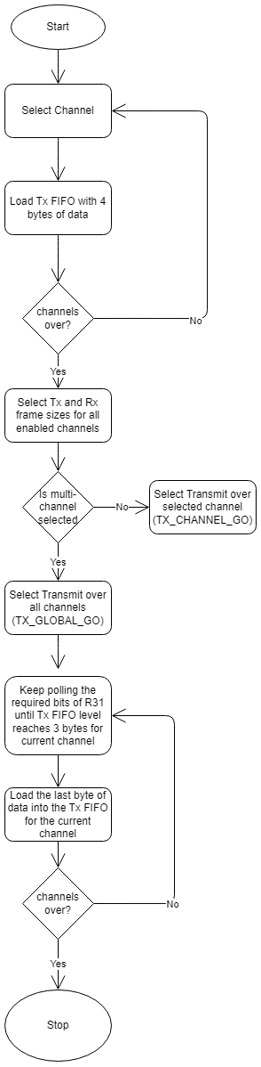
Once the Transmission is complete, the encoder starts sending the data and the firmware copies the receive FIFO contents onto the receive buffer, individually, until all the data has been received.

Depending on the data ID used for initiating the transfer, the firmware parses the received data and copies it onto relevant fields in the interface, accordingly.

The CRC is the last byte of the received data. The firmware then calculates the CRC of the received data excluding the last byte, compares it with the received CRC value, and updates the CRC status in the interface.

 1.8.20