Using SysConfig with MSPM0
1. Introduction
This guide describes how to install and get started using SysConfig with MSPM0.
Note: This guide describes support for MSPM0 production devices and doesn’t support early experimental silicon. Refer to the Early Samples Migration Guide for more information.
1.1. SysConfig Description and Recommended Use
The SysConfig tool is delivered as a standalone installer, integrated in CCS, it can be manually integrated into IAR and Keil, or can be used via the dev.ti.com cloud tools portal.
2. Downloading and Installing MSPM0 SysConfig
These instructions are required when using the standalone SysConfig installer, which is currently neccessary for IAR, Keil or other IDEs. IDEs other than CCS can use this version of SysConfig in their applications, or just use the files generated by it. There are additional steps in section Getting Started with MSPM0 SysConfig to integrate this version within CCS.
Download SysConfig from TI.com
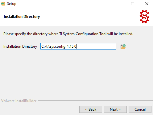
Install SysConfig
3. Getting Started with MSPM0 SysConfig
This section describes how to integrate and use the standalone version of SysConfig in various IDEs, as well as open a Project.
3.1 Getting Started using CCS
These instructions are required in order to integrate the standalone SysConfig in CCS, and successfully build an example.
3.1.1 Enabling SysConfig in CCS
CCS 12.2+ and CCS Theia 1.0+ include a SysConfig version which is compatible with MSPM0, thus not requiring any additional steps to use it. The steps below apply only when integrating a standalone version of SysConfig in cases such as upgrading the SysConfig version.
- Follow instructions from the MSPM0 SDK QuickStart Guide for CCS Theia to install CCS Theia for MSPM0.Alternatively, follow instructions from the MSPM0 SDK QuickStart Guide for CCS to install CCS for MSPM0.
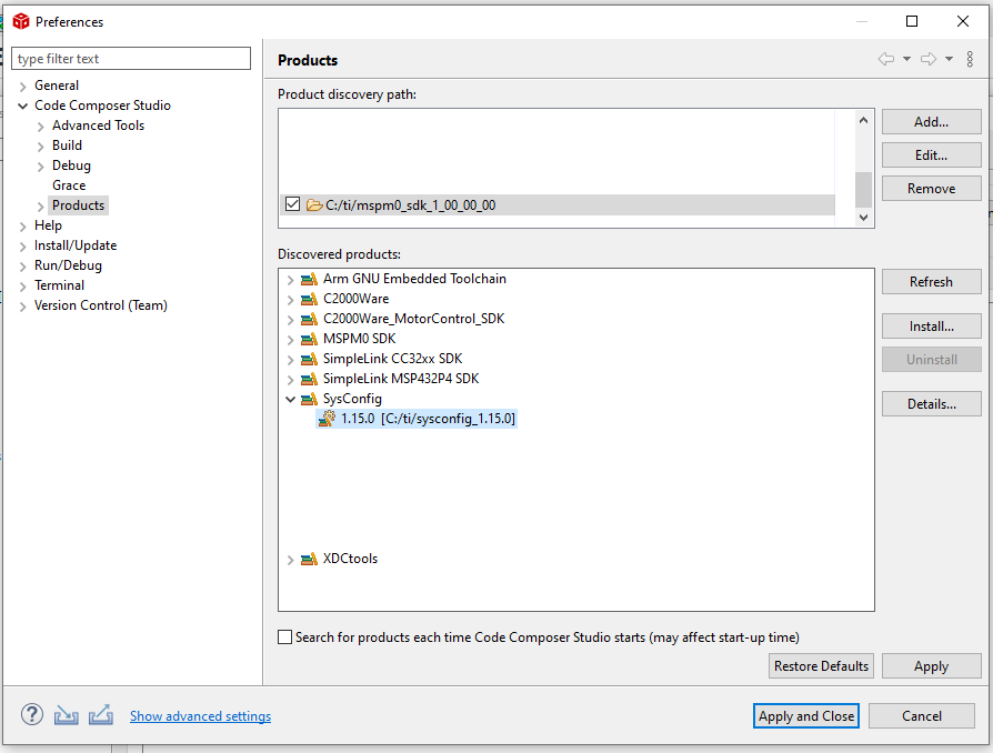
Update CCS tool path. This can be done by clicking Window→Preferences then in the pop-up choose Code Composer Studio→Products, simply refresh after the install and the product should be found underneath SysConfig. Hit apply and close to make the change take effect.
3.1.2 Importing MSPM0 SysConfig Project using CCS
- Follow instructions in MSPM0 SDK QuickStart Guide for CCS Theia to install the MSPM0 SDK and import an example in CCS Theia.Alternatively, follow instructions in MSPM0 SDK QuickStart Guide for CCS to install the MSPM0 SDK and import an example in CCS.Refer to the MSPM0 SDK Examples Guide for a full list of examples with SysConfig support.For an empty example, use the “empty” example.
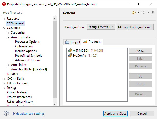
- Check the SysConfig version used by the project.This step is recommended to verify the project finds the correct standalone version, but it can be skipped.2.1. Open Project Settings→CCS General→Products and confirm the SysConfig version is the desired one.If it is not, select SysConfig and click Edit.
2.2. A window will be shown to select the product version. Click on Preferences.
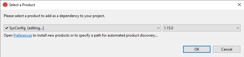
2.3. Verify that the SysConfig path is to the new standalone. A refresh may be needed in order to find it. If not check the paths and installation of SysConfig
- Build the code example.After a successful build, double-click the .syscfg file to start using SysConfig.
3.2 Getting Started using IAR
The best way to start a SysConfig project in IAR is to import it from the SDK; however, some steps are required to initialize SysConfig in IAR for the first time.
3.2.1 Enabling SysConfig in IAR
Follow instructions in MSPM0 SDK QuickStart Guide for IAR to install the MSPM0 SDK.
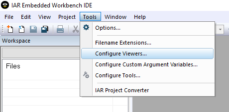
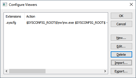
In IAR, select Tools → Configure Viewers from the menu.
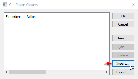
Click Import
Navigate to your SDK folder into
<MSPM0_SDK_INSTALL_DIR>/tools/iar/and open sysconfig_iar_setup.xml.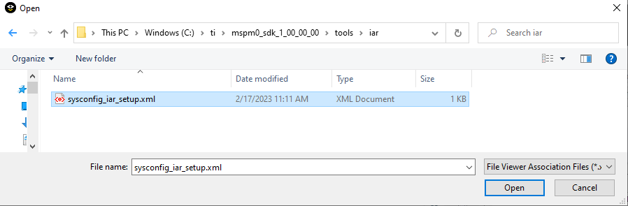
- The standalone SysConfig will be associated to .syscfg files.Click OK to close window.
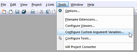
Select Tools → Configure Custom Argument Variables.
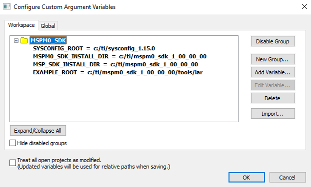
If the MSPM0_SDK variables are not shown, ensure this step is followed as described in MSPM0 SDK QuickStart Guide for IAR, as summarized below.
7.1. In IAR, click on Tools → Configure Custom Argument Variables
7.2. Click the Global tab, and then Import
7.3. Navigate to your SDK folder into
<MSPM0_SDK_INSTALL_DIR>/tools/iar/and open MSPM0_SDK.custom_argvars.7.4. The SDK variables should now be installed in IAR. Click OK to close the window.
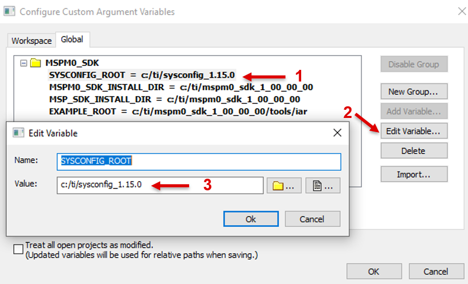
If the SYSCONFIG_ROOT variable is not pointing to the correct path of your SysConfig installation described in section Downloading and Installing MSPM0 SysConfig, edit the variable as shown below:
3.2.2 Importing MSPM0 SysConfig Project using IAR
Follow these steps to import and use a SysConfig project in IAR.
- Import a code example with SysConfig support enabled in to your workspace as described in MSPM0 SDK QuickStart Guide for IAR.Refer to the MSPM0 SDK Examples Guide for a full list of examples with SysConfig support.For an empty example, use the “empty” example.
Double click on the *.syscfg file in your project.
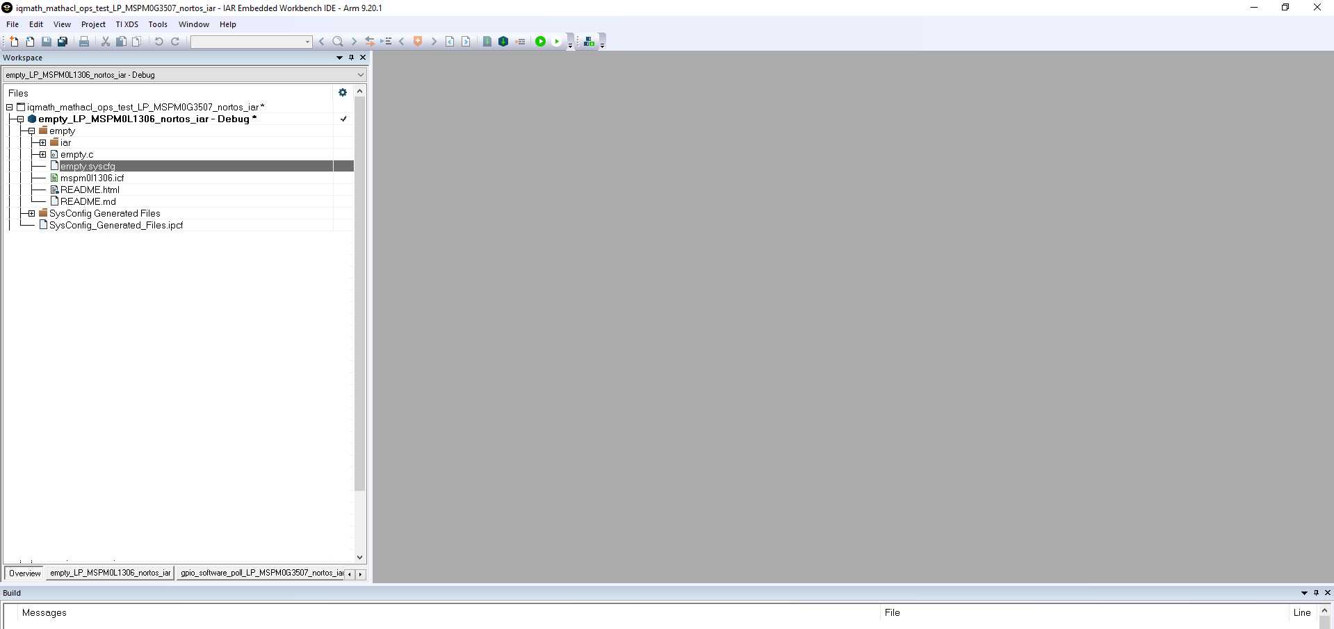
This will open SysConfig and allow you to configure peripherals, IO pins, and other settings.
Save your changes and switch back to IAR EWARM.
Build your code example.
Note: “Rebuild All” can cause an error the first time a project is built. Execute another “Rebuild All” or use “Clean” and then “Make”.
3.3 Getting Started using Keil
The best way to start a SysConfig project in Keil is to import it from the SDK; however, some steps are required to initialize SysConfig in Keil for the first time.
3.3.1 Enabling SysConfig in Keil
Follow instructions in MSPM0 SDK QuickStart Guide for Keil to install the MSPM0 SDK.
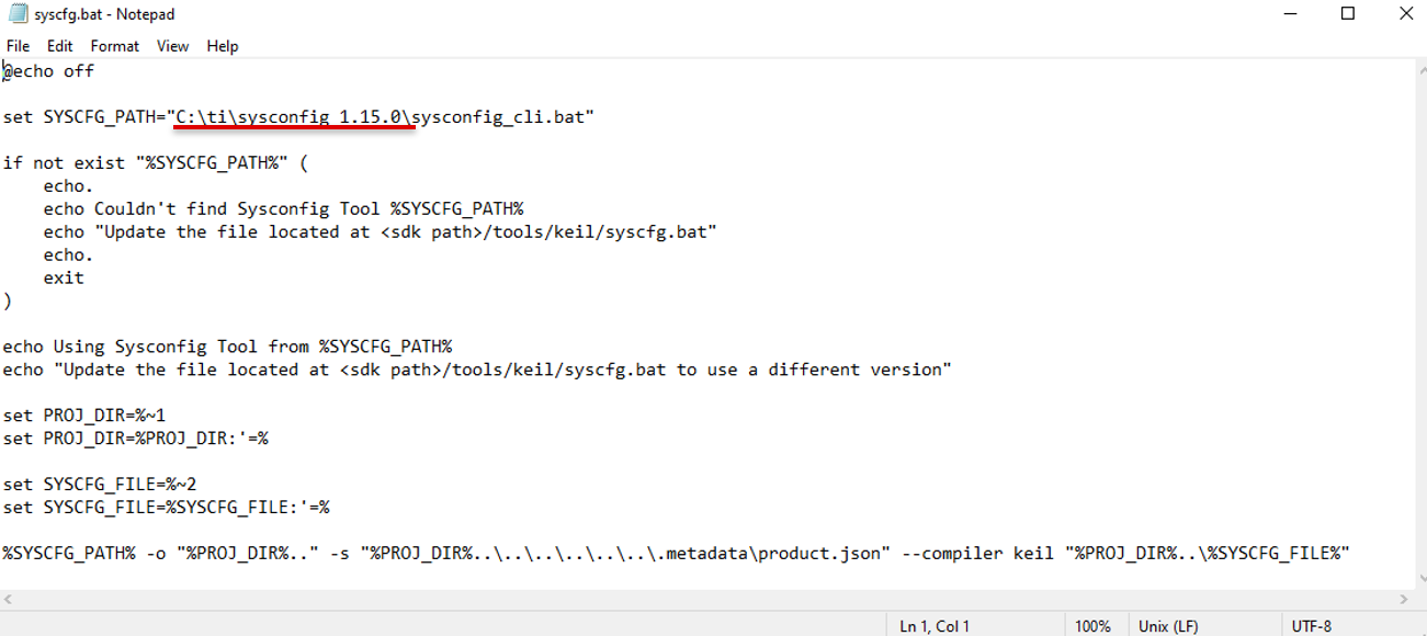
Navigate to your SDK folder into
<MSPM0_SDK_INSTALL_DIR>/tools/keil/and opensyscfg.batfor editing (not executing).Modify the SYSCFG_PATH shown in red below to match the standalone SysConfig path that was selected during section Downloading and Installing MSPM0 SysConfig.
On the same folder, open
<MSPM0_SDK_INSTALL_DIR/tools/keil/MSPM0_SDK_syscfg_menu_import.cfgfor editing.Modify the SysConfig and SDK versions and paths.
The SysConfig version and path is highlighted in red and it should match what was selected during section Downloading and Installing MSPM0 SysConfig.
The SDK version and path is highlighted in blue and corresponds to the
MSPM0_SDK_INSTALL_DIR.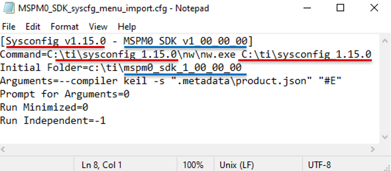
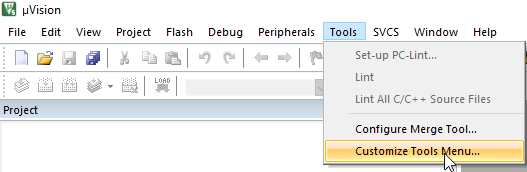
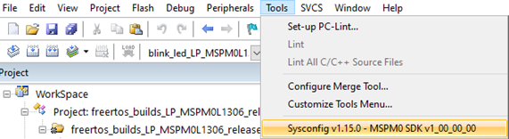
In Keil uVision, select Tools → Customize Tools Menu from the menu.
Click Import
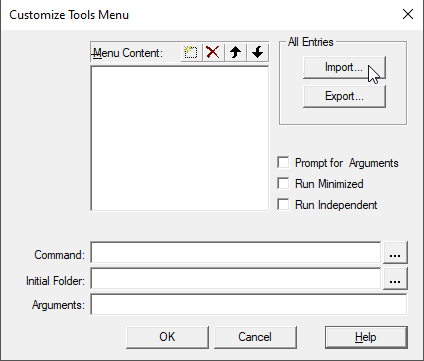
Navigate to your SDK folder into
<MSPM0_SDK_INSTALL_DIR>/tools/keil/and open MSPM0_SDK_syscfg_menu_import.cfg.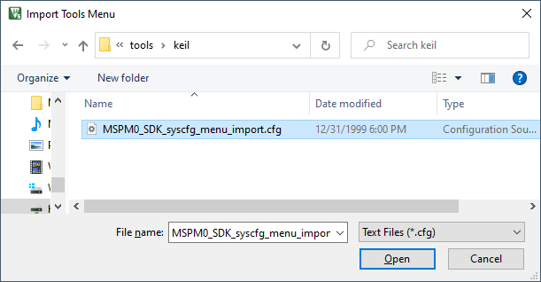
Click OK to close window.
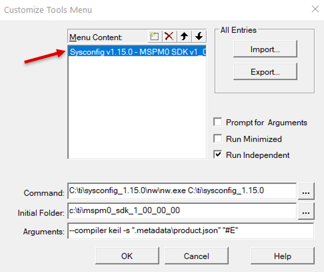
The Tool will now appear on the menu. It will be used to open the GUI as explained on the next section.
3.3.2 Importing MSPM0 SysConfig Project using Keil
Follow these steps to import and use a SysConfig project in Keil.
- Import a code example with SysConfig support enabled in to your workspace as described in MSPM0 SDK QuickStart Guide for Keil.Refer to the MSPM0 SDK Examples Guide for a full list of examples with SysConfig support.For an empty example, use the “empty” example.
Double click on the *.syscfg file in your project.
With the *.syscfg file opened on the viewer, click on Tools and select the tool configured on section Enabling SysConfig in Keil.
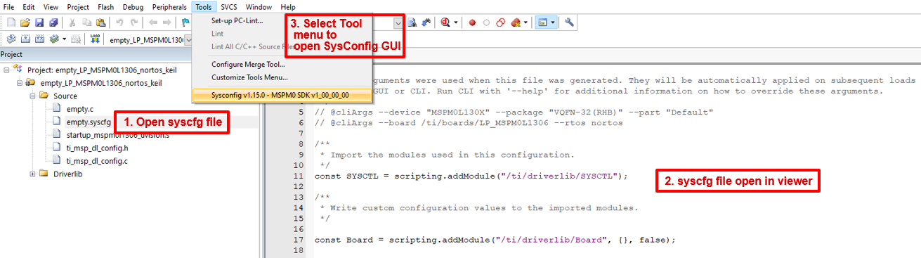
- This will open SysConfig and allow you to configure peripherals, IO pins, and other settings.Note that this approach only allows one SysConfig GUI to be open at a time.
Save your changes and switch back to Keil uVision.
Build your code example.
3.4 Getting Started without an IDE
The following steps describe how to start a SysConfig project using MSPM0 without an IDE. The standalone version can be used for code generation and to evaluate the capabilities of the device, but is not capable of runnning an example.
Run the standalone version of SysConfig
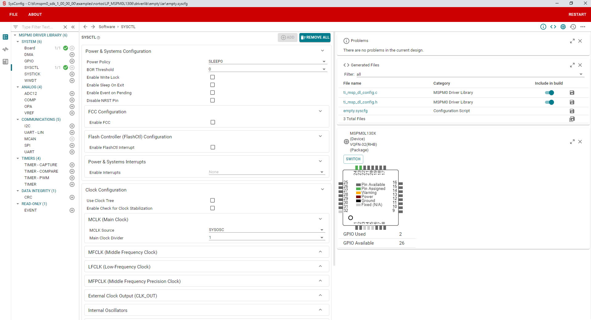
SysConfig 1.15+ includes support for MSPM0 and supports M0 SDK:
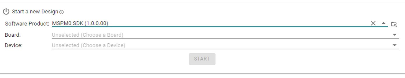
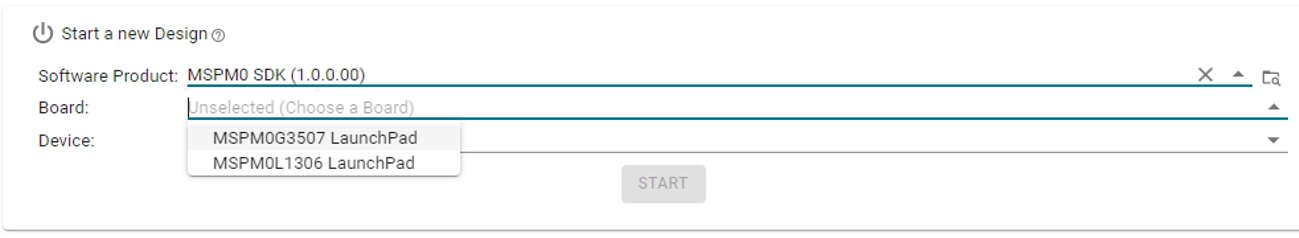
Select the MSPM0 SDK product, and the device.
3.1. Select a board which pre-selects the device and package.
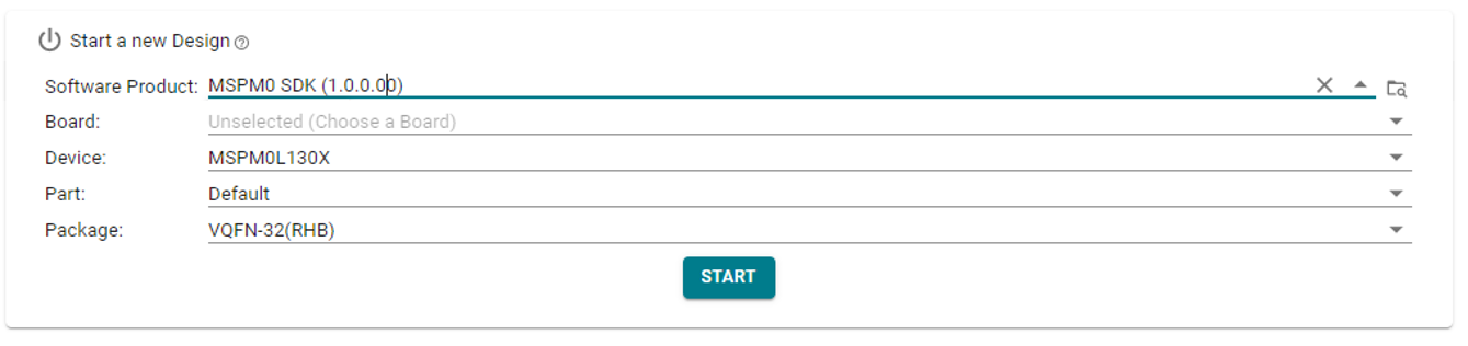
3.2. Or, select a device and package.
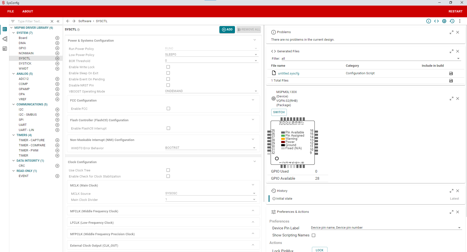
Start using SysConfig
4. Using SysConfig with MSPM0 SDK
This section describes useful features of SysConfig when developing for MSPM0.
4.1 SysConfig Software Modules
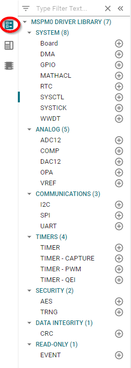
4.1.1 List of Software Modules
4.1.2 Module Description
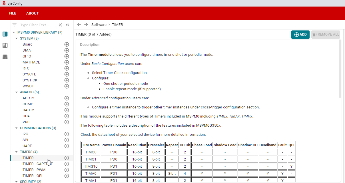
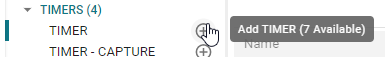
4.1.3 Adding a Software Module
A module can be added as shown below. Note that SysConfig will only add as many instances as supported by the selected device.
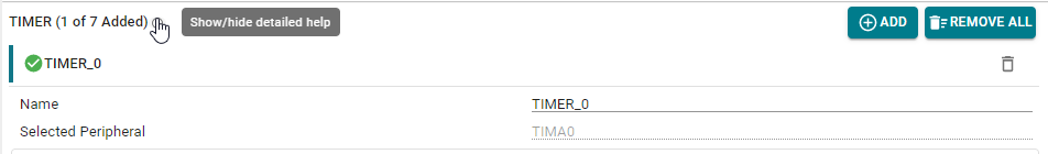
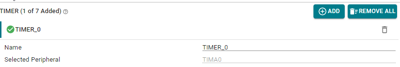
Adding a module will automatically hide its description; however, it can be opened again by clicking the icon shown below:
4.1.4 Components of a Software Module
Software modules vary in functionality, but they typically include the following sections:
- Name:Custom name of the module instance.The name starts with the number “0” as a suffix by default; however, the name can be customized by the developer to reflect the purpose of the module (e.g. “LED_ERROR” for a GPIO, or “TIMER_HEARTBEAT” for a TIMER).Note that the actual peripheral selected by the module is shown below (e.g. “TIMA0”).
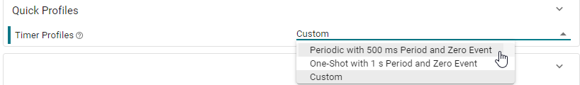
- Quick Profiles:Short list of some common configurations used for the module.Besides providing a quick way to configure the module, these configurations can be used as a guideline to observe which parameters should be customized for each configuration.Note that after modifying any parameter, the profile will default to “Custom”.
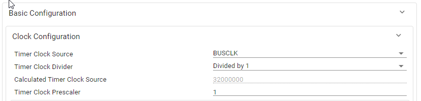
- Basic Configuration:Provides access to the most commonly used settings and features of a module.This section is expanded by default.
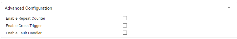
- Advanced Configuration:Provides access to less common but still useful module settings and features.This section is collapsed by default.
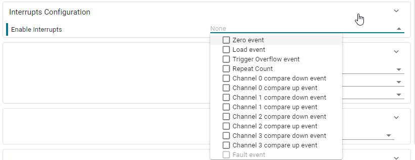
- Interrupts Configuration:Selects which interrupts are enabled or disabled for the module.This section is collapsed by default.
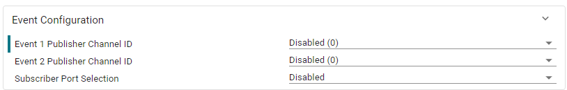
- Event Configuration:Configures the Publisher and Subscriber events for the module.See section Event Configuration for more detailed information on how to configure Events in SysConfig.This section is collapsed by default.
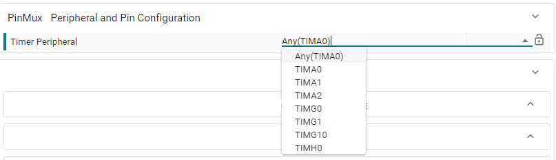
- PinMux - Peripheral and Pin Configuration:Configures the hardware peripheral and pins used by the module. See section PinMux Configuration for more details about hardware selection.
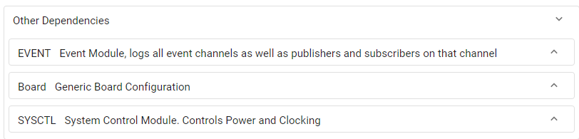
- Other Dependencies:Provides quick access to other dependencies used by the module.
4.1.5 Detailed Description of Parameters
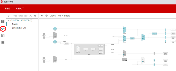
4.2 Clock Tree
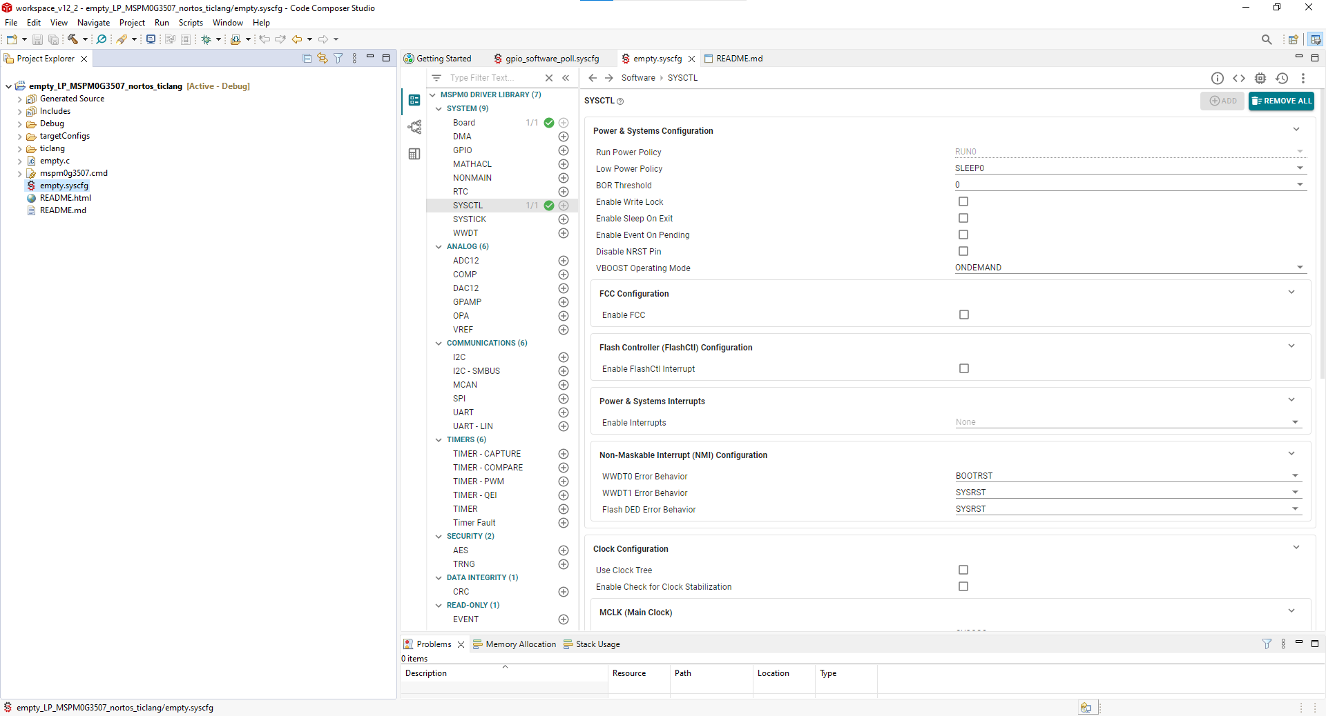
The Clock Tree feature allows the user to configure the clocking of a device graphically rather than using SYSCTL menus. This feature is Clock Tree and can be found by clicking the signal icon near the top left corner of SysConfig. Note the highlighted icon at the top of this page that opens on MSPM0G3507.
Note: the modules and views may differ on SDK version.
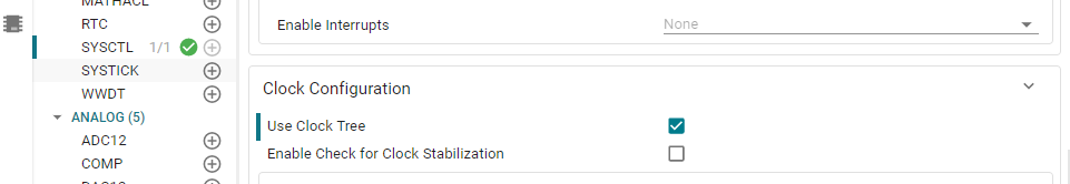
To enable Clock Tree, simply add the SYSCTL module and click “Use Clock Tree” as shown below. This will source code generation and all functions from Clock Tree rather than from the SYSCTL module.
4.2.1 Coloration Scheme And Legend
In SysConfig, there are different colors and shapes that represent the different states of the Clock Tree. There are three possible states and colors that different elements in the Clock Tree can be. They are:
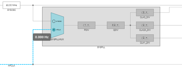
Active (blue): The element is in use and has a non-zero signal at at least one input
Unused (light gray): The element is not in use by the current view, but does have a non-zero clock signal into at least one input (even if it’s not outputted)
Off (dark gray): The element does not have a non-zero clock signal at any input, regardless of if its usage.
The notion of “in-use” describes an element that is in the signal chain of one or more elements that do not have any outputs shown on the graph.
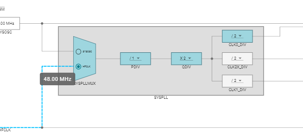
The below image shows the SYSPLL grouping with the channel SYSPLL0 getting output to MCLK. Thus, the path through to MCLK is active, however, other channels are light gray and unused.
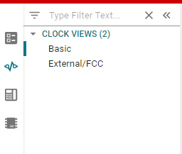
Additionally, M0 devices currently have two separate views in the Clock Tree. A basic view to configure the internal signals, and an external/FCC view where the signals can be sent out or to the Frequency Clock Counter (FCC). One can toggle between the views by clicking them in the top right pane as shown below.
4.2.2 Editing Different Clock Tree Components
Clock Tree components can be edited by clicking on them. There are several different types of components that live in Clock Tree. To get more information about a component, one can simply click on the component to see the available configurables. The major categories are as follows:
Divider/Multipliers: These are arithmetic components in the signal path. They can be adjusted by clicking on the dropdown and selecting the correct number.
Frequency Labels: These are generally labeled signals that can reflect the frequency on the line in order to easily ascertain what is the current state of the signal.
FCC: The frequency clock counter is represented by a single box, and can be enabled and configured by clicking on the box in the external view window.
Gates: These are smaller rectanular blocks that the signal passes through. Some gates are fixed, while others can be enabled/disabled by toggling the checkbox inside.
Muxes: These are adjustable by clicking the buttons inside the mux to select the source signal to be output.
Pin Functions: These are the smaller boxes with an “X” over them, and these all correspond to a resource in the pinmux. To enable them, click on the function and then click enable in the description. This will add the device to the pinmux data as well. There may additional configurables such as HFXT where an input frequency is required in order to know what the other frequencies will be.
Note: Just because CLKOUT appears enabled, this does not mean that code is being generated. It must be clicked on and enabled.
Oscillators: SYSOSC and LFOSC are also present on the device, and SYSOSC does have some configurables and options that can be checked by clicking on the oscillator.
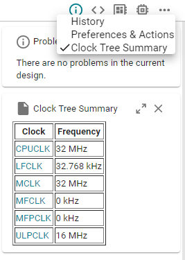
4.2.3 Summary Views
Clock Tree also has a summary pane view that can be found on the far right of the screen when selected from the top right. This can be useful as a quick reference when developing.
4.3 NONMAIN Configurator
The NONMAIN Configurator is a SysConfig module that helps the user configure the device boot routines. The configuration data used by the boot configuration routine (BCR) and bootstrap loader (BSL) are stored in a dedicated region of flash memory called NONMAIN, and the configuration data structures are protected by 32-bit CRCs to improve security. Refer to the Architecture chapter in the device TRM for more details.
Valid device configuration data and the corresponding valid CRC must be programmed into NONMAIN for the device to boot, otherwise the device will become locked in an unrecoverable state.
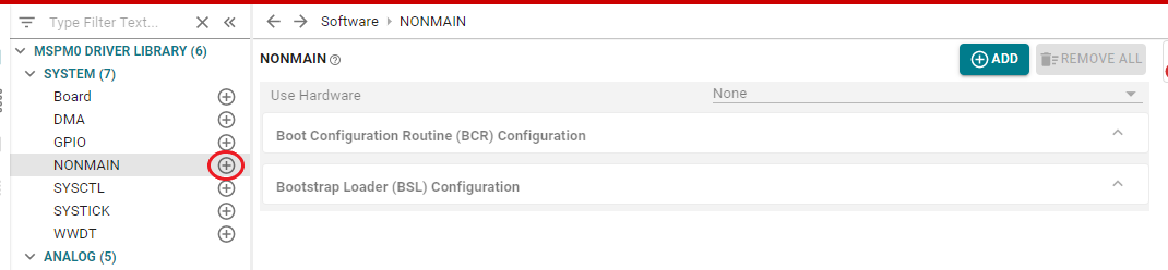
The NONMAIN Configurator helps the user safely configure the device boot routines by automatically calculating the CRCs based on the user-selected values. The NONMAIN Configurator can be added to a project by adding the NONMAIN module as shown below.
When the NONMAIN Configurator module has been added, SysConfig will generate two files: boot_config.h and boot_config.c.
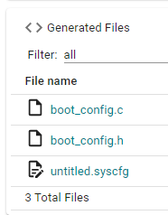
The boot_config.h file contains various enums, defines, and typedefs representing the configuration data structures and the selectable options.
The boot_config.c file contains the configuration data structures with the user-selected values.
When these files have been added to a project, and the project has been built and downloaded to the device, the updated boot routines will take effect after the next BOOTRST.
Note that the generated NONMAIN structures must be placed in the corresponding memory locations by using linker files. The MSPM0 SDK includes linker files showing this functionality for TI Arm-Clang, GCC, IAR, and Keil.
Refer to the SDK BSL examples (bsl_i2c_flash_interface, bsl_uart_flash_interface, secondary_bsl) and the Driverlib example flashctl_nonmain_memory_write for more details on using these files in a project.
4.4 Info, Warnings and Errors
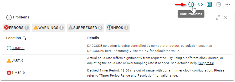
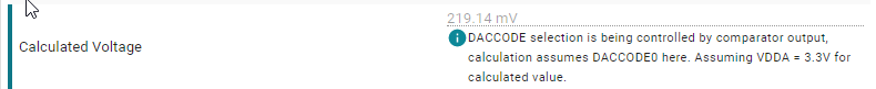
This information message informs the developer that the DAC output will depend on the comparator output, and it assumes a reference supply of 3.3V.
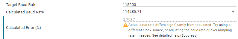
The warning message informs that the calculated UART baudrate differs from the desired target value. This might be OK depending on the tolerance required by the application, so the warning could be suppressed.
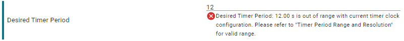
The error message informs that the selected timer period is not possible with the current configuration. This error must be fixed to generate code properly.
4.5 Code Generation
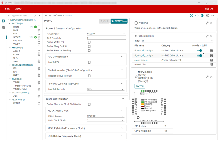
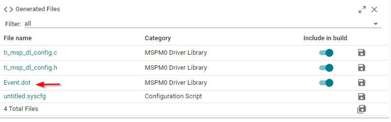
The generated files can be shown or hidden by clicking the icon highlighted below.
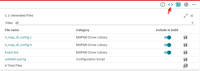
Click on any file to open it on the integrated editor.
4.5.1 Observing code changes based on configuration
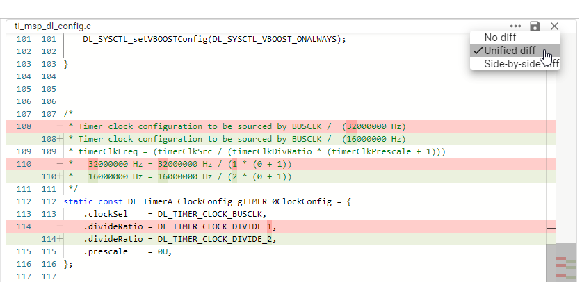
SysConfig can highlight differences in code generation which is a very useful feature when modifying parameters.
Unified diff highlights the recent changes on the same file.
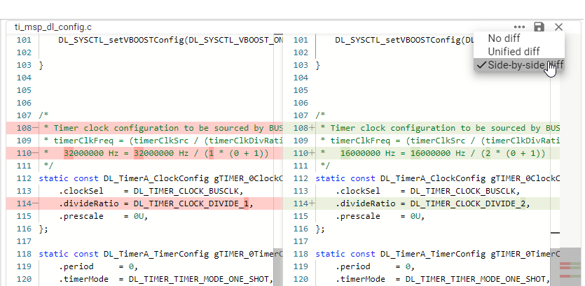
Side-by-side diff shows the newly generated code side-by-side with previous code.
No diff simply shows the latest generated code.
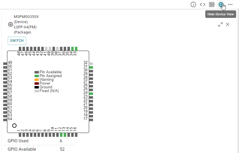
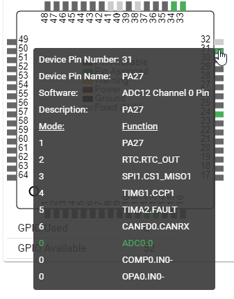
4.6 Device View
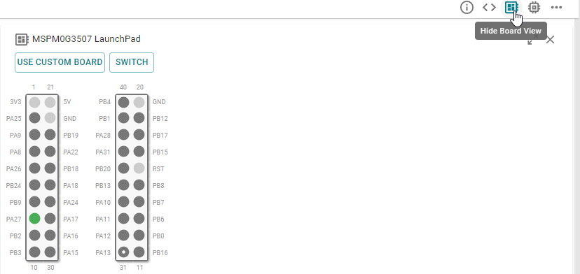
4.7 Board View
4.7.1 Customizing board configurations
Follow these instructions to override or eliminate board constraints.
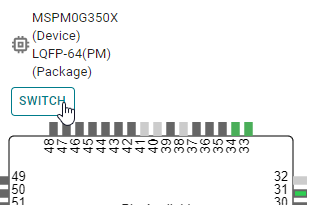
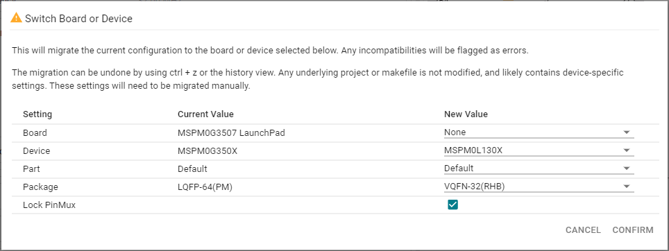
4.8 Switching Between Devices and Packages
Select the new hardware and click on CONFIRM.
4.9 Event Configuration
Select a module with event publisher capabilities. This example uses a TIMER.
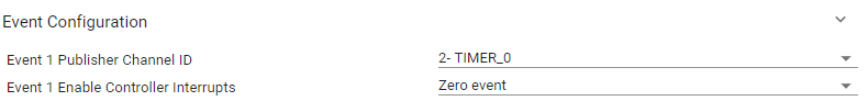
Go to the Event Configuration section of the publisher module.
- Select an ID from 1-15 and the event that will be published.The example below selected ID #2, and the Timer Zero event.
Select a module with event subscriber capability. This example uses an ADC.
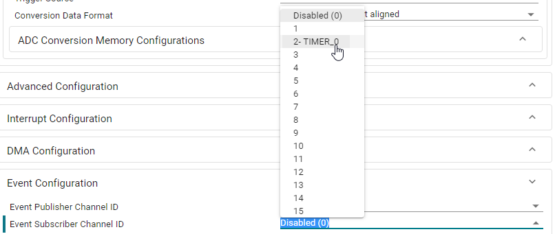
Go to the Event Configuration section of the subscriber module.
- Select the Subscriber Event Channel ID. Note that SysConfig will show which publishers are already configured.For the example below, it shows TIMER for ID #2.
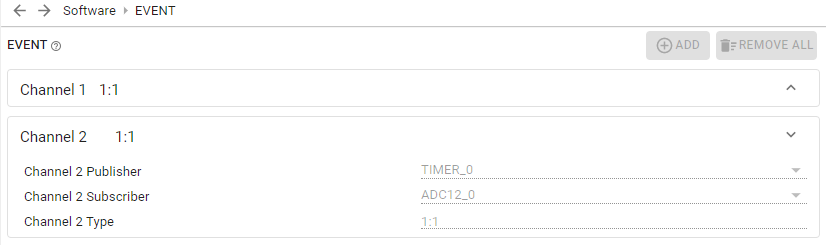
- Open the READ-ONLY EVENT module to see all events.Note that Channel #2 is configured to trigger from TIMER to ADC.
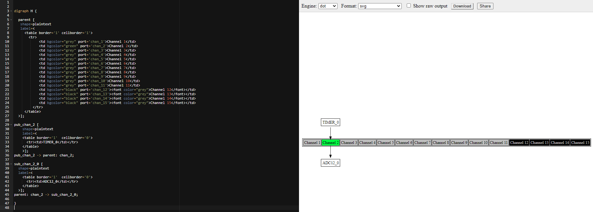
SysConfig also generates an Event.dot file which has a graphical representation of Events.
- Copy the contents of the generated Events.dot into a .dot file viewer such as GraphvizOnline.Observe that Channel #2 is configured to trigger from TIMER to ADC.
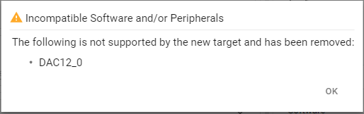
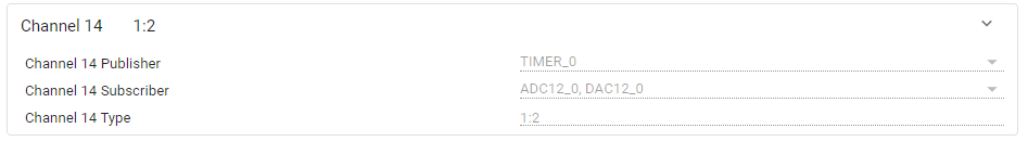
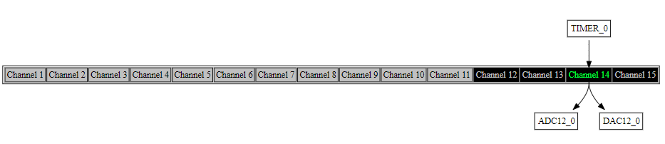
Some event channels support multiple 2 subscribers. The example below shows the configuration of a Timer Publisher triggering an event to the ADC and DAC12 as Subscribers.
4.10 PinMux Configuration
SysConfig enables easy assignment of peripherals and device pins.
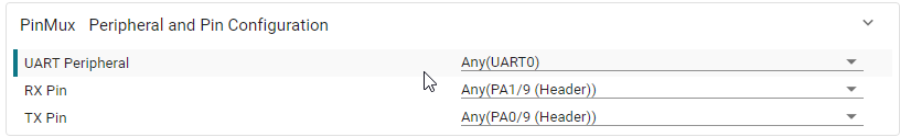
- All modules with assignable hardware contain a PinMux section at the bottom of the module configuration panel.By default, modules are assigned to Any which will allow SysConfig to choose any available peripheral and pin.The following shows the default assignment for a UART module.
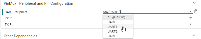
Developers can select a specific peripheral or pin.
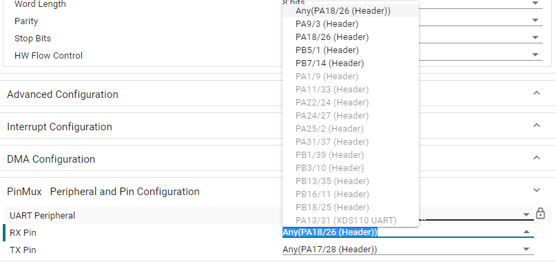
- Note that selecting a peripheral or pin will narrow down the options for other settings.In the example below, only UART1_RX pins can be selected since the peripheral was selected as UART1.
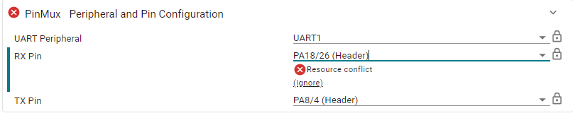
- Selecting a peripheral or pin can cause conflicts if the assignment is not possible.In the example below, PA18 is being used by another module, thus causing an assignment conflict.
4.11 Reserving Hardware Peripherals
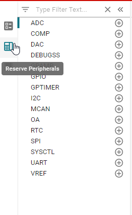
4.11.1 Reserve Peripheral List
The Reserve Peripheral list for MSPM0 SDK can be selected by clicking the icon shown below.
4.11.2 Reserving a peripheral
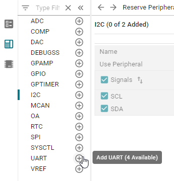
The assignment of the peripheral and pins is similar to PinMux configuration.
4.12 Disabling SysConfig
Once the initial configuration for the application is complete, developers may wish to freeze or lock-in the files generated by SysConfig, so they are not re-generated in future builds.
4.12.1 Disabling SysConfig in CCS
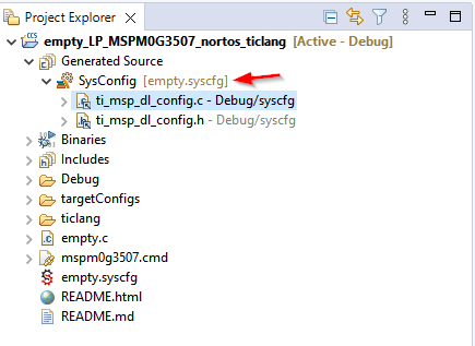
Locate Generated Files
Generated files can be located in the CCS Project Explorer in the Generated Source folder:
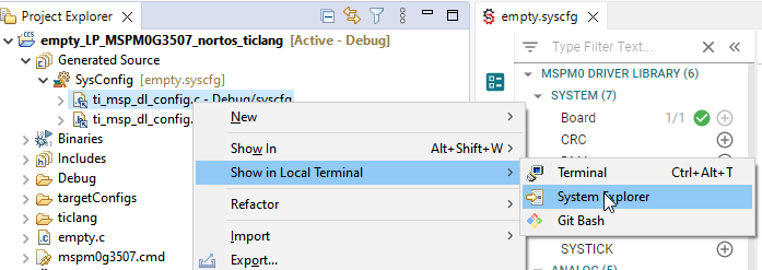
These files will be located in <project>/<build_configuration>/syscfg which can be accessed in a quick and easy way by right-clicking on any of the files in the folder above and selecting Show in Local Terminal → System Explorer
Copy Generated Files
Create a new folder. In the figure below shown as
<project>/sysconfig.Copy the generated source files from the
<project>/<build_configuration>/syscfgmentioned in previous step.Paste the generated source files to the new folder.
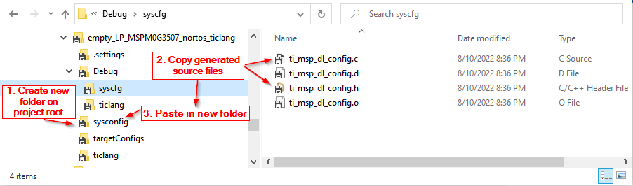
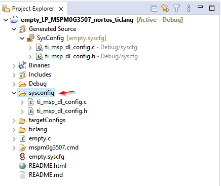
Note that the files will now show in CCS:
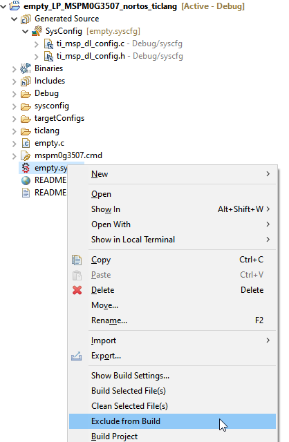
Disable SysConfig
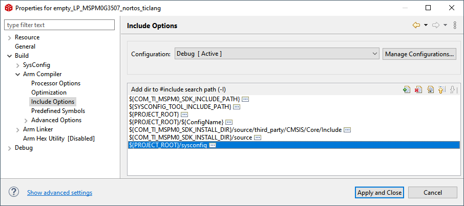
Modify Compiler/Linker Settings
The following image shows how to add the path ${PROJECT_ROOT}/sysconfig to include the header files from the newly created folder.
Rebuild Project
The project can now be rebuilt without SysConfig.
Re-enabling SysConfig
Include the .syscfg back into the project.
Exclude or delete the new folder containing the previously copied files.
Remove any project settings that could cause conflicts between the folders.
4.12.2 Disabling SysConfig in IAR
Locate Generated Files
Generated files can be located in the IAR Workspace in the SysConfig Generated Files folder:
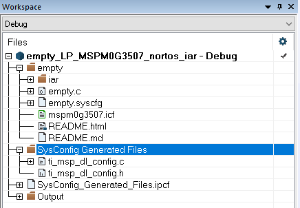
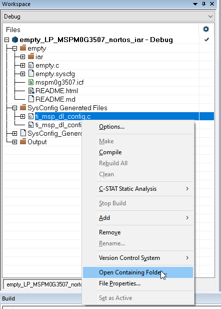
These files will be located in the project root folder. The files can be accessed in a quick and easy way by right-clicking on any of the files in the folder above and selecting Open Containing Folder
Disable SysConfig
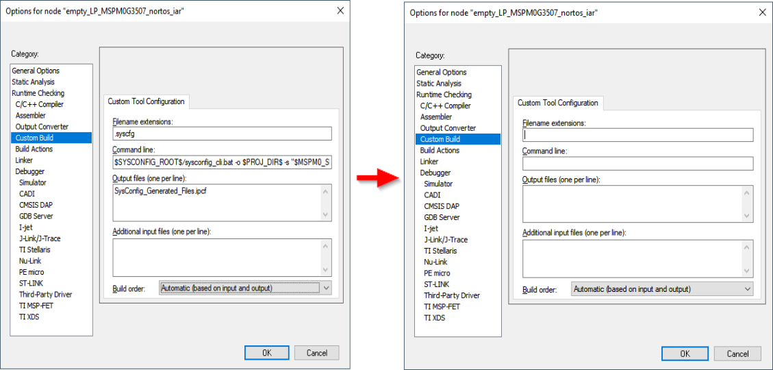
In IAR, SysConfig is treated as a Custom Build step. To access the custom build steps, select Project→Options→Custom Build. Remove all the fields that are populated under the Custom Tool Configuration tab as shown below:
Rebuild Project
The project can now be rebuilt without SysConfig.
Re-enabling SysConfig
Restore the Custom Build settings from Project→Options→Custom Build:
1.1. Filename extensions:
.syscfg1.2. Command line:
$SYSCONFIG_ROOT$/sysconfig_cli.bat -o $PROJ_DIR$ -s "$MSPM0_SDK_INSTALL_DIR$/.metadata/product.json" --compiler iar $FILE_PATH$1.3. Output files:
SysConfig_Generated_Files.ipcf