DRV8706-Q1 EVM GUI Hardware Guide
1. Overview
To run DRV8706-Q1 EVM examples the user must properly modify the motor driver evm, connect the evm’s pin with the LaunchPad’s pins, connect the motor and power on the motor driver evm.
2. Whats Needed
Soldering Iron – To remove onboard resistors.
14x Female Jumper Wires
Brushed DC motor
Power Supply that supports your motor driver and motor’s voltage and current requirement.
3. Board Modifications

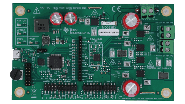
All the resistors shown in the yellow rectangle above needs to be desoldered from the motor driver evm. These pins connects the onboard MCU to the motor driver. Removing these resistors will allow the user to connect the motor driver pins to an external MCU.
4. Launchpad and Motor Driver Pin Connections
4.1 LP-MSPM0L1306
The below tables shows the pins on the LaunchPad that should be connected to the motor driver’s evm pins via a jumper wire. Note that some pins on the LaunchPads require removal or adjustments of onboard jumpers.
LP-MSPM0L1306 Pins |
LP Notes |
DRV8706-Q1 EVM Pin |
|---|---|---|
GND (Any GND Pin) |
GND |
|
3V3 (Any 3V3 Pin) |
DVDD |
|
PA12 |
IN1/EN |
|
PA13 |
Remove J3 |
IN2/PH |
SW2/PA11 |
Set J14 to PA11 & SW2 |
SCLK |
PA5 |
SDI |
|
PA10 |
SDO |
|
PA15 |
Remove J1 jumper |
nSCS |
PA27 |
Remove J13 jumper |
SO |
PA24 |
Remove J5 jumper |
nSLEEP |
PA21 |
DRVOFF |
|
PA6 |
nHIZ1 |
|
PA22 |
Remove J6 jumper |
nHIZ2 |
PA17 |
nFAULT |
5. Motor Connections
The motor driver supports a variety of control modes. How you connect your motor or solenoid to the motor driver’s evm will depend on the control mode you want to use.
5.1 H-Bridge and Phase Enable Control Mode

Each end of the motor should be connected to OUT1 and OUT2.
5.2 Half-Bridge Mode

For each motor, one pin goes to one of the outputs and the other pin goes to other GND or PVDD. Both motors can have one side connected to GND or PVDD if the user desires. Above shows Motor 1 connected to OUT1 and GND while Motor 2 is connected to OUT2 and PVDD.
5.3 Solenoid Mode
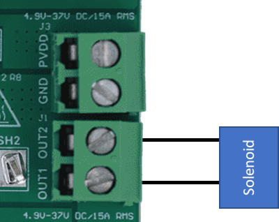
Each end of the solenoid should be connected to OUT1 and OUT2.
6. Powering the EVM

The evm’s VBAT and GND connector on the top right of the evm must be connected to a power supply. The voltage must stay within 4.9 V and 37 V to satisfy the motor driver’s recommended analog voltage range.