MSPM0 LIN User’s Guide
1. Introduction
LIN (Local Interconnect Network) is a serial network protocol that allows for simple and inexpensive communication in automotive networks. The MSPM0 SDK provides an easy way to start development of LIN applications using the MSPM0’s Universal Asynchronous Receiver Transmitter (UART) module.
Example applications are provided in the SDK to demonstrate how to configure a MSPM0 device as a LIN 2.x Controller or Responder.
Note: The use of “Master” and “Slave” terminology is being considered obsolete. These terms have been replaced with “Controller” and “Responder” respectively.
For supporting LIN protocol, the following hardware enhancements are implemented in the UART module:
16 bit up-counter (LINCNT) clocked by the UART clock
Interrupt capability on counter overflow
16 bit capture register (LINC0) with two configurable modes:
Capture of LINCNT value on RXD falling edge, with interrupt capability on capture
Compare of LINCNT with interrupt capability on match
16 bit capture register (LINC1), with configurable mode:
Capture LINCNT value on RXD rising edge, with interrupt capability on capture
The MSPM0 SDK LIN applications are only meant for basic evaluation of LIN using the UART hardware and/or guidance to implement LIN drivers. It is not meant to provide a full automotive-qualified LIN stack.
2. Configuring the UART for LIN with SysConfig
LIN mode is supported on UART peripherals with UART Extend functionality. Refer to the device data sheet for the device-specific details on the UART peripherals.
Users can easily configure their device for LIN by using SysConfig. Refer to the Using SysConfig with MSPM0 for more details on how to download, install, and get started with SysConfig.
To add LIN to your project in SysConfig, add the UART-LIN module as shown below.

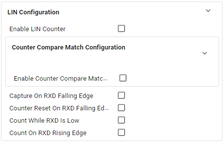
Along with allowing the user to configure the basic UART properties for the UART peripheral, the UART-LIN module also allows users to configure the following LIN settings:
These settings are discussed in more detail in the sections below.
Enable LIN counter

This enables the 16 bit up-counter LIN counter, LINCNT. The LIN counter will only count when the counter is enabled.
Enable and configure LIN Counter Compare Match mode

The Counter Compare Match mode allows the user to detect timing between edge events. This is done by enabling the LIN counter, LINCNT, to be compared to a set value in the 16 bit capture register, LINC0. This functionality is useful for LIN break detection where a valid break can be detected when RXD is low for 9.5 consecutive bits.
When this mode is enabled, SysConfig provides the calculated value of one Tbit, where a Tbit is the nominal time required to transmit a bit. Tbit is calculated as:
Tbit = (UART Clock Source Frequency) / (UART Baud Rate)
For example, with a clock source of 32MHz, a baudrate of 19200bps, Tbit Width is:
Tbit = (32,000,0000) / (19,200) = 1,666
The user can provide the counter compare value in Tbits. For example, to set the to set the counter compare value to 9.5 Tbits, the user should set the Counter Compare Timing value to “9.5”.
After setting the value in Tbits to be compared to, SysConfig provides the value in cycles that the counter compare register LINC0 is set to. In this example, the Counter Compare Value in cycles is 15,833.
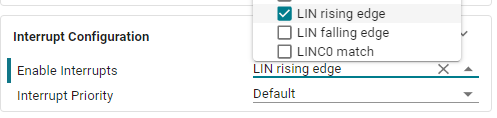
Interrupt capability can be enabled to trigger on a counter compare match. Select the LINC0 match interrupt in the Interrupt Configuration section to enable triggering an interrupt on match with the set counter compare value.

When Counter Compare Match mode is enabled, the other mode of LINCNT, Capture on RXD falling edge, is automatically disabled. These options are mutually exclusive.
Enable Capture on RXD Falling Edge

Capture on RXD Falling edge allows the user to validate the timings of events. This is done by configuring the 16 bit capture register, LINC0, to capture the value of the LIN counter, LINCNT, on a RXD falling edge. This can be used in conjunction with the Enable Capture on RXD Rising Edge feature to perform SYNC field validation by measuring the bit timings of the signal, and using the values in LINC0 and LINC1 to validate the capture timings.
Interrupt capability can be enabled to trigger on an RXD falling edge. Select the LIN falling edge interrupt in the Interrupt Configuration section to enable triggering an interrupt when the LINC0 counter captures a value to the LINC0 register on each RXD falling edge.

When Capture on RXD Falling Edge is enabled, the other mode of LINCNT, Counter Compare Match mode, is automatically disabled. These options are mutually exclusive.
Enable Counter Reset on RXD Falling Edge

When Counter Reset on RXD Falling Edge is enabled, the LIN counter, LINCNT, will be reset to a value of 0 when a falling edge of RXD is detected. The LIN counter will immediately continue to count after the value is reset. This is useful during SYNC field validation to continuously count the bit times on each new falling edge.
Enable Count while RXD is Low

When enabled, the LIN counter, LINCNT, will count while there is a low signal on RXD. This is useful for break field detection, so the LIN counter can count the length of the RXD low signal to determine if it is a break field. The LIN counter must be first enabled before counting.
Enable Capture on RXD Rising Edge

When enabled, the 16-bit capture register, LINC1, will capture the value of the LIN counter, LINCNT, on each rising RXD edge. This can be used in conjunction with the Enable Capture on RXD Falling Edge feature to perform SYNC field validation by measuring the bit timings of the signal, and using the values in LINC0 and LINC1 to validate the capture timings.
Interrupt capability can be enabled to trigger on an RXD rising edge. Select the LIN rising edge interrupt in the Interrupt Configuration section to enable triggering an interrupt when the LINC1 counter captures a value to the LINC0 register on each RXD rising edge.
Quick Profile
A Quick Profile is provided in the UART-LIN module that gives some basic recommendations on how to configure the LIN settings.
The LIN at 19220 baud with Break Detection Quick Profile configures the UART peripheral at 19200 baud, and configures the LIN setting to handle break detection.


After selecting the profile, users can then modify these settings to be further suited for their application.
Refer to the device specific Technical Reference Manual (TRM) for more details on the UART LIN configuration.
3. Example Applications
The MSPM0 SDK provides two example applications to use as a starting point for LIN applications:
lin_commander: Configures the UART as a LIN Commander, and demonstrates basic transmit of LIN 2.0 packet using enhanced checksum
lin_responder: Configures the UART as a LIN Responder, and demonstrates break field detection and sync field validation of the received LIN header
These examples can be found at <SDK_INSTALL_DIRECTORY>/examples/nortos/<LaunchPad>/lin.
The lin_commander and lin_responder examples can be used on two separate MSPM0 devices to communicate with each other. Alternatively, a Network Analyzer compatible with LIN 2.0 can be used with either example as well.
The LIN examples in the SDK are used with the Texas Instruments BOOSTXL-CANFD-LIN BoosterPack, which features the TLIN2029-Q1 fault protected LIN transceiver.
Refer to the examples README files for more details on connecting the MSPM0 LaunchPad to the LIN transceiver, as well as detailed instructions on how to run the example.
Modifying the Example Applications
Each LIN example application include a lin_config.c and lin_config.h file. These files contain macros that can be modified based on the user applications. It is recommended to only change these macros once the user has gained familiarity with the usage of the example application.
lin_config.h contains the definition of the struct LIN_table_record_t which allows the user to define a PID, the number of bytes associated with the data field for that PID, as well as a callback function for when that PID is received.
Below is an example definition of a LIN_table_record_t struct:
LIN_table_record_t messageTable[LIN_COMMANDER_NUM_MSGS] = {
    {0xBA, /* PID 0x3A */
        8,
        NULL},
    {0x0D, /* PID 0x0D */
        5,
        LIN_processMessage_Rx}
};
In this example, the first struct member is {0xBA, 8, NULL}.
0xBAis the frame ID representing a PID of 0x3A. Refer to the LIN specification on how to determine the PID.8is the number of bytes that is expected in the data field for a packet with PID 0x3A.NULLtells the application that no callback function should be called when a packet with PID 0x3A is received.
The second member of the struct is {0x0D, 5, LIN_processMessage_Rx}. This member definition points to the user-defined callback function LIN_processMessage_Rx, which tells the application to call this function when a packet with PID 0x0D is received.