|
AM64x MCU+ SDK
12.00.00
|
|
|
AM64x MCU+ SDK
12.00.00
|
|
In the prior versions of the SDK, linker files presented challenges in terms of ease of maintenance. Linker files were generated from templates, meaning that any alterations to parameters such as stack size, heap size, memory regions, or sections necessitated direct edits to the linker files. This process proved to be cumbersome and difficult to manage.
The Memory Configurator tool seamlessly integrated into sysconfig empowers users to configure critical parameters. By utilizing this tool, corresponding linker files are automatically generated. This feature significantly streamlines the process, eliminating the need for manual adjustments to the linker files and providing users with a hassle-free experience.
Please refer to the section "By-passing Sysconfig generated Linker" to use hand written linker file.

Suppose core 0 has a memory region named MEM0 with a start address of 0x0 and a length of 16KB. Core 1, on the other hand, possesses a memory region named MEM1 with a start address of 0x4000 and a length of 64 KB. Now, in the event that the user wishes to expand the size of MEM0, this action would necessitate an adjustment in the start address of MEM1 while ensuring its size remains unchanged. Furthermore, if there are any other memory regions defined immediately after MEM1, all corresponding adjustments would need to be made. The integration of this tool facilitates these modifications, sparing the user the need to manually edit each individual configuration.
There are scenarios where a core attempts to configure the Memory Protection Unit (MPU) for a memory region that hasn't been assigned to it. This constitutes a violation that requires proper handling.
Another common error involves designating a shared memory region as cached. This tool serves as a safeguard against such mistakes, ensuring that these violations and configuration errors are prevented.
Within the tool interface, the user will find a section labeled "MEMORY" on the left pane. This section encompasses three key components: "General," "Memory Region," and "Sections."
In the forthcoming discussion, each of these components will be explored in detail. This will equip users with the knowledge and guidance required to configure the tool in alignment with their specific requirements.
Within this section, the user will have the option to configure essential parameters such as stack size, heap size, IRQ (Interrupt Request), FIQ (Fast Interrupt Request), SVC (Supervisor Call), Abort Stack and Undefined Stack sizes.
Upon adding an instance, these parameters will be automatically populated with their default values.
Additionally, the user will have the capability to select the compiler, which will determine the syntax for generating the linker files.

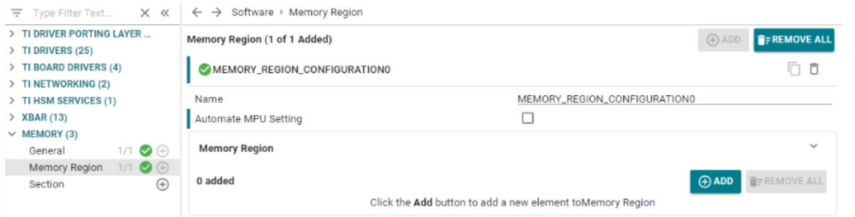
The Memory Region configuration is a pivotal aspect with several integrated features.
Upon clicking the "Add" button, an option titled "Automate MPU Setting" will become available. By default, this option will remain unchecked. In this scenario, users can add memory regions without any associated MPU settings, unless configured otherwise. There is no restriction on the size in the sense that it doesn't need to be power of 2 and can take any value within its memory type limit.
If the user opts to check this option, it signifies that each memory region instance may be linked to a maximum of one MPU configuration. This implies that when a user adds a memory region instance and desires to include an MPU setting, they are exempted from the manual entry of parameters such as address and size.
The tool employs a specific algorithm for memory region allocation:
Here is an illustration to explain the above:


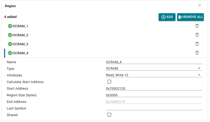
In this configuration, there are four designated regions: OCRAM_1 and OCRAM_2 have auto-generated start addresses, while OCRAM_3 and OCRAM_4 possess manually assigned ones. Following the algorithm's guidelines, the regions with manual start addresses, OCRAM_3 and OCRAM_4, take precedence. They are first accommodated within the OCRAM space. Subsequently, three gaps remain: one to the left of OCRAM_3, another between OCRAM_3 and OCRAM_4, and a third to the right of OCRAM_4. The algorithm then selects the smallest available gap to house the largest auto start address region, OCRAM_2.
Afterwards, OCRAM_1 is placed in the gap adjacent to OCRAM_2, as it is the smallest one capable of accommodating OCRAM_1.

The other fields which we have for configuring a memory region are:


If we want to test some dependent core individually in a multi-core project, then you need to add those shared regions by opening the syscfg for that core only.
Eg:
And not,
But the thing to note here is that now when you build system project, there will be conflict coming from the independent core sharing these regions and your current core under test as it will have the same regions added twice (once by the independent and other by itself). Then we will have to remove those from the dependent ones.
When the "Automate MPU Setting" option is selected, the tool's behavior is adjusted to align with MPU setting rules. Specifically, memory regions cannot be placed anywhere within a hole; they must be situated at an address that starts at a multiple of their size. The size must be a power of 2 starting from 32 B through 4 GB.
MEM0 and MEM1, both 32B regions of the same type, are arranged as depicted. However, MEM2, which is 128B in size, cannot be positioned immediately after MEM1 due to alignment constraints. Placing it there would result in a start address that is not a multiple of its size. Consequently, the region is relocated to an address where the start aligns with its size, thereby generating a gap between MEM1 and MEM2.

An MPU setting will be generated with parameters (such as start address and size) mirroring those of its associated memory region. Please note that these parameters will be locked and cannot be altered by the user. Other parameters, such as Access Permissions, Region Attributes, Allow Code Execution, and Sub-Region Disable Mask, can be customized by the user.


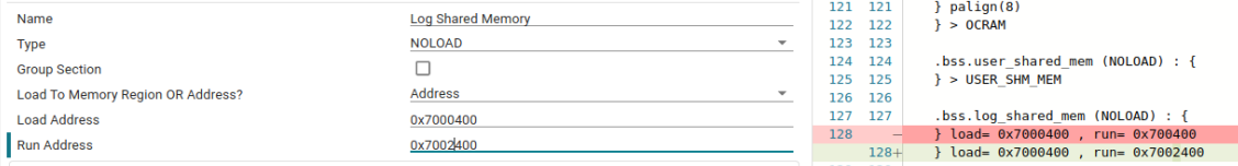
Within this section, the user has the option to set various parameters for a section.

Once the "Select Multiple Memory Regions" is checked, user will get the option to select the priority of the memory regions. Here the section will be put to the first memory region (in the order) big enough to accommodate the entire section. The Priority 0 contains MSRAM, Priority 1 contains NON_CACHE_MEM and Priority 2 contains USER_SHM_MEM.

Once this option is checked, again in the similar way the user will get options to choose the priority of memory regions. The difference here is the redirection symbol which is ">>" instead of ">". What this means is that the section will spread across multiple regions following the order if the first one is unable to entirely fit it in.

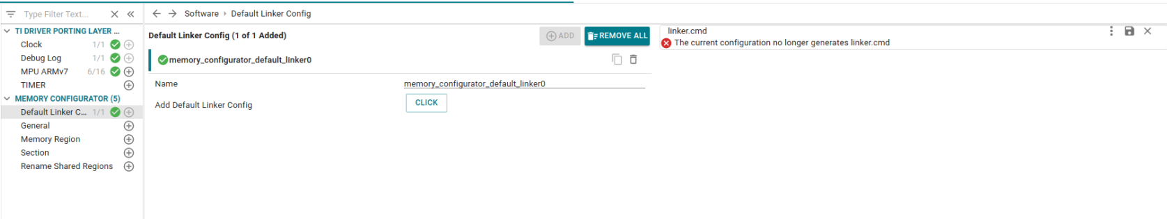
Initially when we open an empty project, no memory configurator related configuration will be there and hence linker.cmd won't generate. User can either add the configurations manually or may take the help of this CLICK button to populate the default instances of these modules to generate a default linker. Later it can be edited/ added/ removed as per our needs.

As discussed earlier, let's revisit the functionality of MPU settings with the Automate option.
When the user selects the "Automate MPU Settings" option within the Memory Region, they will have the opportunity to configure the MPU settings specific to that memory region. Note that in this scenario, the start and size parameters are fixed and cannot be altered. This enhancement aims to streamline the configuration process, alleviating the need for separate MPU adjustments.
However, it's worth mentioning that there may be instances where users prefer the flexibility to customize MPU settings. In such cases, they have the option to disable the automation feature.
When "Automate MPU Setting" is not selected within the memory region, it results in the loss of the direct one-to-one mapping of the memory region to the MPU configuration view. In such cases, it is beneficial to provide users with a comprehensive overview of how the region is composed.
This should encompass the following information :

This approach ensures that users have a clear understanding of how the manually configured MPU settings relate to the broader memory regions and their usage across different cores.
To facilitate user understanding and ease of navigation, a specialized view has been incorporated. This view provides a visual representation of the memory types available in this device, displaying crucial details such as start address, size, accessibility across cores, and direct links to the respective memory regions for seamless navigation.

A similar visual representation has been integrated for MPU configurations. This view presents a detailed tabulation of all configurations, providing users with a clear overview of their settings.

In case user wants to write their own linker file instead of the sysconfig generated one (as earlier versions of SDK), they can achieve that by following some simple steps:
<file path="linker.cmd" openOnCreation="false" excludeFromBuild="false" action="copy"> </file>  1.8.20