- Note
- A53 and Linux will not be available on all SOCs. All references to Linux and A53 should be ignored on such SOCs.
Introduction
AM64X SOC has multiple CPUs on which distinct applications are run. These applications need to communicate with each other to realize the larger system level application. This means of communication is called Inter Processor Communication (IPC).
The section describes the below details related to IPC
- IPC SW architecture as it spans across different CPUs and operating systems.
- Steps to enable IPC in your applications running RTOS, NORTOS or Linux
Additional References
See also these additional pages for more details and examples about IPC,
- Message passing using IPC
- Mutual exclusion across CPUs
- Debug logging in multi-core environment
- Examples using IPC
IPC SW Architecture
Shown below is a block diagram of the SW modules involved in IPC,
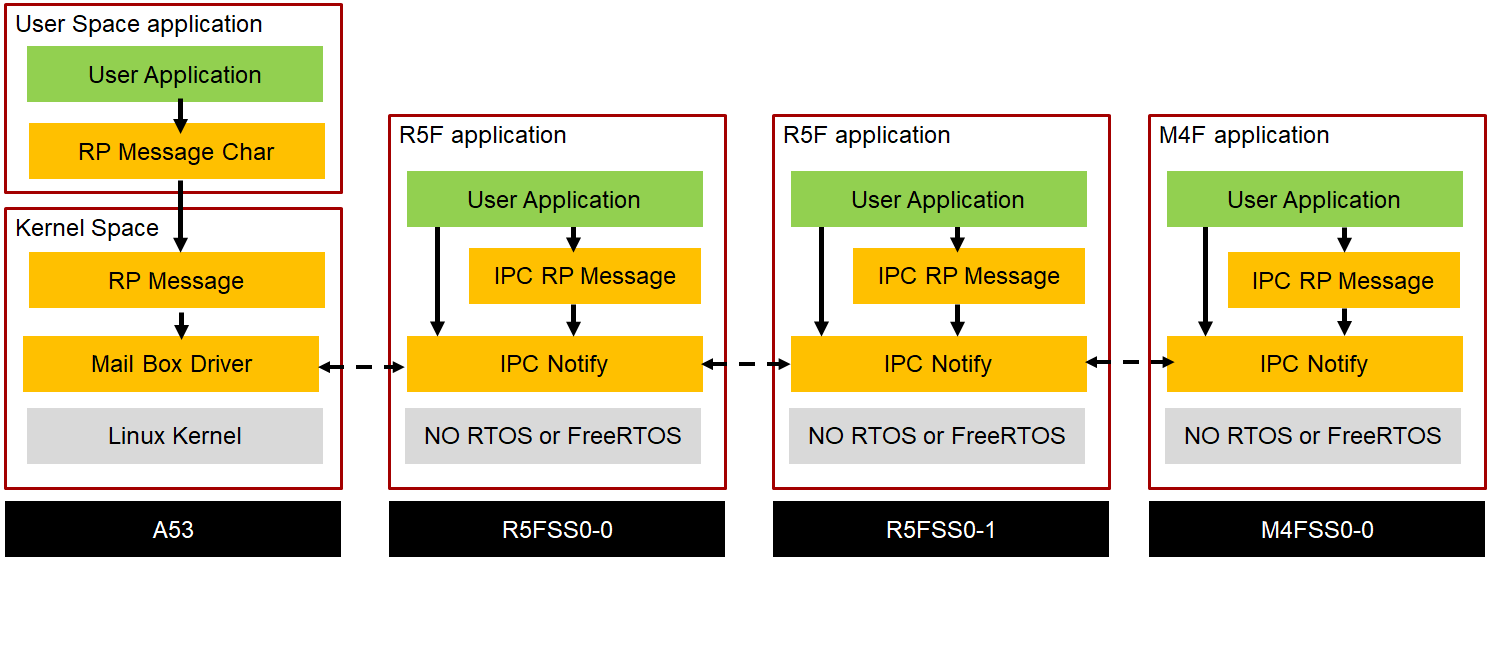
IPC SW Block Diagram
IPC involves synchronizing between SW running across multiple CPUs. This is achieved by exchanging messages between the CPUs.
IPC Notify and IPC RP Message
There are two APIs to exchange messages between the CPUs
- IPC RP Message,
- Here a CPU can send messages as packet buffers to a logical end point or port on another CPU
- The packet buffers themselves are kept in a "shared memory" which is visible to both the participating CPUs
- When a packet is put into the shared memory, a CPU needs to interrupt or "notify" the other CPU that there is a new packet to process. This is done using a HW interrupt mechanism.
- Message packet size
- Packet size when Linux is one end is fixed to 512 bytes. This is fixed in Linux kernel by default.
- Minimum packet size when RTOS/NORTOS at both ends is 4 bytes.
- Max packet size when RTOS/NORTOS at both ends can be defined by end user, though 512 bytes is the max recommended size.
- Larger packet means larger shared memory to hold the messages.
- Logical end points can be up to RPMESSAGE_MAX_LOCAL_ENDPT count.
- IPC Notify
- Here a CPU simply interrupts or notifies the other CPU using a low level HW interrupt mechanism
- This allows the IPC notify to be extremely low latency, with some trade off of flexibility offered by RP Message
- Here, a user can send a 28b message ID along with the interrupt and there can be upto IPC_NOTIFY_CLIENT_ID_MAX logical end points or ports (called client ID's) associated with a CPU.
- Internally, the RTOS/NORTOS implementation of IPC RP Message uses the IPC Notify API underneath
- This allows users to use both RP Message and Notify together in the same application based on their requirements.
When using Linux
When using Linux,
- On the Linux side, IPC RP Message is implemented inside the Linux kernel on top of the HW mailbox driver
- Applications, typically in user space, can access this RP Message kernel module using the
rpmsg_char character driver in user space.
- Processor SDK Linux provides a user space
rpmsg_char library which gives simplified APIs to send and receive messages to other CPUs using RP Message.
Important usage points
Below are some important points to take note of regarding IPC,
- Any CPU can do IPC with any other CPU. Constraints if any are listed below.
- The exact mechanism used for HW interrupts would differ based on the SOC capabilities, but the overall features and API from user application point of view remains the same.
- When Linux is one end of the IPC message exchange, only IPC RP Message can be used.
- When Linux is one end of the IPC message exchange, the max RP Message packet or buffer size is 512 bytes.
- When both ends of the IPC message exchange run RTOS or NORTOS, the max RP Message packet or buffer size is defined by user. Default is 128 bytes. This allows to optimize the memory needed for shared memory in order to fit the shared memory in on-chip RAM.
- When needing to transport larger data more than packet size, it is recommended to pass a "pointer" or "offset" to the data buffer in the message packet rather than copying the data in the message itself.
IPC design pattern
Using the basic send and receive IPC APIs, an application writer can design IPC for his application in many different ways. The final choice depends on the end application requirements.
Given below is a typical "design pattern" of using IPC RP Message in "client server" mode,
- A server CPU typically offers some service, say do some computation or read some sensor,
- The server creates a RP Message end point
- An end point is any 16b number, however in our implementation, we constrain it to RPMESSAGE_MAX_LOCAL_ENDPT, to make the implementation fit a low memory footprint and still be performance efficient.
- An end point is somewhat similar to a port in UDP and CPU ID is somewhat similar to an IP address.
- Thus given a CPU ID and end point on that CPU, any other CPU can send messages or packets to it.
- This end point value is known upfront to all CPUs who wish to communicate with it and they also know the nature of service that is offered.
- The server then waits to receive messages at this end point
- When it gets a message, the message packet indicates the action to do, typically via a command ID that is part of the packet.
- The packet also contains, command specific parameters
- The parameters needs to fit within the packet buffer, if the number of parameters is large or the parameter itself is a large amount of data, then the parameter inside the packet buffer should instead point to another larger shared memory which holds the actual data or additional parameters.
- As part of the received message, the server also gets to know the sender CPU ID and sender reply end point
- After the message is processed, the server can then send a "ack" back to the sender including results from the processing.
- The "ack" itself is simply another message packet and it in turn can have command status and return parameters.
- A client CPU can send messages to this server end point, as below
- It creates a RP Message end point to receive "acks". This end point can be any value and need not match the server end point.
- It calls the send API with the server CPU ID, server end point ID and reply end point ID.
- The send API includes the packet to send, which is filled with the command to execute and parameters for the command.
- After sending the packet, it waits for a reply
- After getting the reply, it processes the reply status and results
- A server CPU can create multiple end points each offering a logically different service.
- On the server side, using separate RTOS tasks to wait for received messages on a given end point is a very common design to choose. Though if carefully designed, no-RTOS mode can also be used within a tight processing loop in the main thread.
- On the sender side, it is common to wait for "ack", however the sender can choose to do something in between while waiting for "ack". "ack" itself can be optional for some commands for example, and is usually agreed between the client and server.
A similar design pattern can be used with IPC Notify APIs, only in this case, the message packet can only be a 28b message value. And the end point values MUST be less than IPC_NOTIFY_CLIENT_ID_MAX
Enabling IPC in applications
Below are the summary of steps a application writer on RTOS/NORTOS needs to do enable IPC for their applications
- Step 1: Enable IPC RPMessage and/or IPC Notify in SysConfig for the CPUs of interest.
- Step 2: Update linker command file to place the shared memory sections at the right place in the memory map
- Step 3: Mark the shared memory sections as non-cached in the MPU/MMU of the CPU. This can be done via SysConfig
- Step 4.a: When IPC with Linux is enabled, sync with Linux during system initialization phase.
- Step 4: Start using the IPC message passing APIs
We use IPC RP Message Echo example as reference to go through each step in detail. It is recommended to open these projects in CCS and refer to the SysConfig UI for these projects as you read through the instructions below.
Enable IPC in SysConfig
- Enable IPC via SysConfig, by selecting
IPC under TI DRIVERS in the left pane in SysConfig.
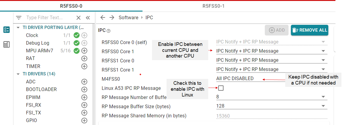
IPC SysConfig
- In the center pane, Select
IPC Notify + IPC RPMessage or IPC Notify or All IPC Disabled for each CPU that the current CPU wishes to communicate with.
- "Check" the
Linux A53 IPC RP Message box if you want to enable IPC between Linux and current CPU
- Adjust the RP message buffer size and number of buffers as needed. This affects the size of shared memory that is needed as shown in the last line in the UI above. This is shared memory between RTOS/NORTOS CPUs.
- NOTE, As we will see later, the shared memory used with Linux is separate.
- This step needs to be repeated for every RTOS/NORTOS CPU. Using system projects in this case helps to view all the CPUs together in SysConfig. See Using SDK with CCS Projects for using system projects with CCS and Using SDK with Makefiles for system projects with makefile.
- If there is any mistake in doing this configuration then SysConfig will report an error and you should then fix it before proceeding.
- When using Linux on Cortex-A, enabling Linux IPC also enables logging to shared memory which can then be read using
debugfs commands in Linux
- When operating in RTOS/NORTOS ONLY mode, i.e no Linux, it is recommended to also enable debug logs via
Shared Memory Log Writer on all CPUs and then on one CPU, enable Shared Memory Log Reader. This makes all the logs, from all the CPUs to be available at one CPU which can then log them to the selected console, like UART terminal.
- See
Debug Log under TI DRIVER PORTING LAYER in left tab in SysConfig to see how this is enabled in the IPC examples. See also Debug for more details.
Update linker command file
- When IPC RP Message is enabled, a shared memory is used to exchange packet buffers between different CPUs. This shared memory MUST be mapped to the same address across all CPUs.
- This is done via the linker command file as shown in below snippet taken from IPC RP Message Echo example
/* specify the memory segment */
MEMORY
{
...
/* shared memories that are used by RTOS/NORTOS cores */
/* On R5F,
* - make sure there is a MPU entry which maps below regions as non-cache
*/
USER_SHM_MEM : ORIGIN = 0x701D0000, LENGTH = 0x00004000
LOG_SHM_MEM : ORIGIN = 0x701D4000, LENGTH = 0x00004000
RTOS_NORTOS_IPC_SHM_MEM : ORIGIN = 0x701D8000, LENGTH = 0x00008000
}
/* map the shared memory section to the memory segment */
SECTION
{
...
/* General purpose user shared memory, used in some examples */
.bss.user_shared_mem (NOLOAD) : {} > USER_SHM_MEM
/* this is used when Debug log's to shared memory are enabled, else this is not used */
.bss.log_shared_mem (NOLOAD) : {} > LOG_SHM_MEM
/* this is used only when IPC RPMessage is enabled, else this is not used */
.bss.ipc_vring_mem (NOLOAD) : {} > RTOS_NORTOS_IPC_SHM_MEM
}
- Strictly speaking for IPC RP Message only
RTOS_NORTOS_IPC_SHM_MEM is needed.
- However the example also shows the below,
- A shared memory segment for shared memory based debug logging (
LOG_SHM_MEM)
- A sample shared memory for generic user application usage (
USER_SHM_MEM)
- The start address for these segments can be anything, only it has to be exactly same across all CPUs.
- Need less to say other memory segments, except the shared memory segments, like code/data/stack across all CPUs should be non-overlapping else each CPU will trample over each other and things will not work as expected.
- When there is Linux in the system, the shared memory is specified via the below additional lines in each CPUs linker command file
MEMORY
{
...
/* On R5F,
* - make sure there is a MPU entry which maps below regions as non-cache
*/
LINUX_IPC_SHM_MEM : ORIGIN = 0xA0000000 , LENGTH = 0x100000
}
- NOTE, that start address for this memory is different in different CPUs linker command file. This segment start address and size is defined in the Linux kernel device tree file (dts) for each CPU.
- Additionally, the section
.resource_table MUST be placed in the SECTIONS field in the linker command file at an alignment of 4K bytes.
GROUP {
/* This is the resource table used by Linux to know where the IPC "VRINGs" are located */
.resource_table: {} palign(4096)
...
} > DDR
Update MMU/MPU for the CPU
- The shared memory sections that are put in the linker command file needs to be mapped as NON-CACHE at the RTOS/NORTOS CPUs.
- This can be done via SysConfig, by adding additional MPU entries using the
MPU module under TI DRIVER PORTING LAYER in SysConfig.
- Once again
- Refer to MPU settings for each CPU in IPC RP Message Echo example for RTOS/NORTOS applications WITHOUT Linux.
- And refer to MPU settings for each CPU in IPC RP Message Linux Echo example when Linux is also present in the system
Sync with CPUs
- When Linux is present in the system, additionally one needs to call below API at each CPU that has Linux IPC enabled after
System_init is done but before any IPC message exchange with Linux is started.
/* This API MUST be called by applications when it's ready to talk to Linux */
status = RPMessage_waitForLinuxReady(SystemP_WAIT_FOREVER);
DebugP_assert(status==SystemP_SUCCESS);
- Also when we create RP Message end point on the RTOS/NORTOS CPU, we need to tell Linux about the end point number as shown below,
RPMessage_CreateParams_init(&createParams);
createParams.localEndPt = 14;
status = RPMessage_construct(&gIpcRecvMsgObject[1], &createParams);
DebugP_assert(status==SystemP_SUCCESS);
/* We need to "announce" to Linux client else Linux does not know a service exists on this CPU
*/
status = RPMessage_announce(CSL_CORE_ID_A53SS0_0, 14, "rpmsg_chrdev");
DebugP_assert(status==SystemP_SUCCESS);
- The name
rpmsg_chrdev is special and is what enables Linux user space to talk to this "announced" end point.
- These steps are not needed when a RTOS/NORTOS CPU needs to talk to another RTOS/NORTOS CPU.
- Sometimes it's useful for the RTOS/NORTOS CPUs to sync with each other and be at a common or well defined point in their initialization sequence. The below API can be used for the same
/* wait for all cores to be ready */
IpcNotify_syncAll(SystemP_WAIT_FOREVER);
Start using the APIs


 1.8.20