|
AM64x MCU+ SDK
08.02.00
|


|
|
AM64x MCU+ SDK
08.02.00
|
|
The Tamagawa receiver firmware running on ICSS-PRU provides a defined well interface to execute the Tamagawa protocol. The Tamagawa diagnostic application described here interacts with the Tamagawa receiver firmware interface.
Tamagawa diagnostic application does below,
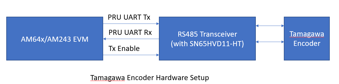
This application is controlled with a terminal interface using a serial over USB connection between the PC host and the EVM. Please connect a USB cable between the PC and the EVM. A serial terminal application (like teraterm/ hyperterminal/ minicom) is then run on the host. To configure, select the serial port corresponding to the port emulated over USB by the EVM. The host serial port should be configured to 115200 baud, no parity, 1 stop bit and no flow control. Connect the Tamagawa encoder via RS485 transceiver to the EVM. The connections between EVM and RS485 logic signals are:
It is necessary to provide 3.3V to the RS485 logic side. The receive transceiver is always kept enabled with bus side connected as in Tamagawa Specification.
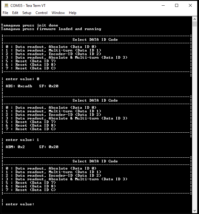
The Tamagawa receiver firmware running on ICSS0-PRU1 provides a defined interface. The Tamagawa diagnostic application interacts with the Tamagawa receiver firmware interface. It then presents the user with menu options to select Data ID code (as defined by Tamagawa) to be sent to the encoder. The application collects the data entered by the user and configures the relevant interface. Then via the Tamagawa receiver interface, the command is triggered. Once the command completion is indicated by the interface, the status of the transaction is checked. If the Status indicates success, the result is presented to the user.
SysConfig can be used to configure things mentioned below:
In general, peripherals or features not mentioned as part of "Features Supported" section are not supported, including the below
| Folder/Files | Description |
|---|---|
| ${SDK_INSTALL_PATH}/examples/motor_control/tamagawa_diagnostic | |
| tamagawa_diagnostic.c | Tamagawa diagnostic application |
| ${SDK_INSTALL_PATH}/source/motor_control/position_sense/tamagawa | |
| firmware/ | Folder containing TAMAGAWA PRU firmware sources. |
| Parameter | Value |
|---|---|
| CPU + OS | r5fss0-0 freertos |
| ICSSG | ICSSG0 |
| PRU | PRU1 |
| Toolchain | ti-arm-clang |
| Board | am64x-evm |
| Example folder | examples/motorcontrol/tamagawa_example |
Shown below is a sample output when the application is run:
 1.8.20