Introduction
Asymmetric multiprocessing (AMP) with FreeRTOS is where each core of a multicore device runs its own independent instance of FreeRTOS. The cores do not all need to have the same architecture, but do need to share some memory if the FreeRTOS instances need to communicate with each other.
FreeRTOS-AMP support is added on all the a53 cores in AM62X. Each a53 core in the device runs its own instance of FreeRTOS.
AMP applications can be loaded via SBL as well as CCS.
Running AMP application
- Note
- Only a few examples, such as hello_world, empty, dpl_demo task_switch, sciclient_get_version and gpio_input_interupt are added for all the 4 a53 cores in am62x. These examples are enough to start AMP application on a53 cores.
-
Output from a53ss0-1, a53ss1-0, and a53ss1-1 cores is logged to shared memory and can be viewed via a53ss0-0 on which the log reader is enabled.
Loading and running a .out file for an AMP application via CCS
CCS can be used to load and run a .out file for each a53 core in am62x. hello_world, empty, dpl_demo, task_switch, and sciclient_get_version examples use the log shared memory to print the output logs from the a53 cores. The user must run a53ss0-0 core as on this core the log reader is enabled. Users can also use different uart consoles for each a53 core to print the output logs.
- Connect the target CPU of interest if not already connected
- User can connect any of the a53 core in am62x as shown in the fig:

Connect A53_1 CPU
- Load program on the CPU

Load Program
- When using makefiles to build,
- In the "Load Program" dialog, select "Browse" and select the program from
examples/{example folder}/{board}/{cpu}_{os}/{compiler} as shown below for the "hello world" program.

Select Program for Makefile Build
- When using CCS projects,
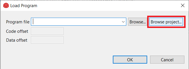
- In the "Load Program" dialog, select "Browse Project",
- select the project and then select the program as shown below,

Select Program for CCS Projects Build

Select the Program from CCS Project
- Other a53 cores can connect and load by the same procedure as above mentioned
- After the program is loaded to all cores, you will see the program is halted at "_c_int00()" as shown below

Program is halted at _c_int00_()
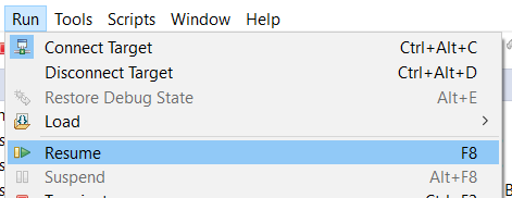
- Select "Resume" to run the program and debug using the various CCS debug options

Run the Program
- The program output will be seen on CCS console, and/or UART terminal, if enabled. Below shows a sample output on both CCS console and UART(UART0) console, after running the "hello world" program.

Run the Program

Run the Program
Loading and running a .out file for an AMP application via SBL UART
hello_world, empty, dpl_demo, sciclient_get_version, and task_switch examples are provided with the config file to run all these examples via sbl uart. Below are examples showing how to run the hello_world example using sbl uart. Like this other example can run
- For am62x-sk
   cd ${SDK_INSTALL_PATH}/tools/boot
   python uart_bootloader.py -p /dev/ttyUSB0 --cfg=${SDK_INSTALL_PATH}/examples/hello_world/am62x-sk/hello_world_freertos-amp_sbl_uart_hs_fs.cfg
- For am62x-sk-lp
   cd ${SDK_INSTALL_PATH}/tools/boot
   python uart_bootloader.py -p /dev/ttyUSB0 --cfg=${SDK_INSTALL_PATH}/examples/hello_world/am62x-sk-lp/hello_world_freertos-amp_sbl_uart_hs_fs.cfg
- For am62x-sip-sk
   cd ${SDK_INSTALL_PATH}/tools/boot
   python uart_bootloader.py -p /dev/ttyUSB0 --cfg=${SDK_INSTALL_PATH}/examples/hello_world/am62x-sip-sk/hello_world_freertos-amp_sbl_uart_hs_fs.cfg
gpio_input_interrupt example
gpio_input_interrupt example can be loaded and run using CCS as explained above. This example uses the same gpio pin for all the 4 a53 cores and output from all these cores are printed via different UART. A53_CORE0, A53_CORE1, A53_CORE2 and A53_CORE3 use UART0, UART1, WAKEUP_UART and MCU_UART respectively. Users can use any gpio pin on any a53 core for interrupt functionality.
- Attention
- A GPIO bank interrupt can be routed to only one core at a time. For example, if a gpio interrupt is routed to the A53_0 core, the same cannot be routed to other cores (A53_1/A53_2/A53_3). In the case of AMP, currently, all cores are using the same SPI_MAIN_GPIOMUX_INTROUTER and GPIO mux introuter output number. Users can change this and can use different gpiomux interrupt router for each a53 core by making the following changes in the board.c file.
% if(args.project.cpu == "a53ss0-1"){
#define BOARD_BUTTON_GPIO_INTR_NUM (CSLR_GICSS0_COMMON_0_SPI_MAIN_GPIOMUX_INTROUTER0_OUTP_1)
#define BOARD_BUTTON_GPIO_SWITCH_NUM ("GPIO0_14")
%}
% else if(args.project.cpu == "a53ss0-1"){
#define GPIOMUX_INTROUTER_OUTP (1U)
%}
ATF
- Trusted Firmware-A (TF-A) is build separately for each a53 core
- TF-A load address is different for each a53 core
- For a53ss0-0 TF-A load address is 0x80000000
- For a53ss0-1 TF-A load address is 0x82080000
- For a53ss1-0 TF-A load address is 0x86000000
- For a53ss1-1 TF-A load address is 0x88080000
- 4 distinct TF-A build binaries are used because TF-A jump address or preload base address is different for each a53 core
- For a53ss0-0 TF-A jump address is 0x80080000
- For a53ss0-1 TF-A jump address is 0x82100000
- For a53ss1-0 TF-A jump address is 0x86080000
- For a53ss1-1 TF-A jump address is 0x88100000
- TF-A logs from a53ss0-0 are printed to UART0 and logs from other cores are blocked
- TF-A logs can be seen when the applicataion loads via SBL UART. hello_world example output with TF-A log is shown below

hello_world_with_atf_log
- The default log level for the release build is 20 and the debug build is 40. i.e., will see more logs from TF-A when examples run in the debug profile
Linker File update
- Separate linker.cmd file is used for each a53 core
- DDR Memory region is divided and allocated to each a53 core
- From 0x80080000 to 0x82080000 is allocated to a53core0
- From 0x82100000 to 0x84100000 is allocated to a53core1
- From 0x86080000 to 0x88080000 is allocated to a53core2
- From 0x88100000 to 0x8A100000 is allocated to a53core3
- Different TF-A jump address is used for each a53 core
- Shared Memory among all the a53 cores are defined
MMU and Cache configuration
- MMU configuration is done on each a53 core
- LOG shared memory is non-cacheable (MAIR4 in SysConfig)
- Memory region used in the spinlock is outer and inner write back cacheable and nontransient (MAIR7 in SysConfig)
- TF-A Region is read-only and non-shareable
- SMP enable bit is set to attain data coherency b/w cores, this is required in spinlock
GIC Configuration
- SGI(INT 0-15) and PPI (INT 16-31) interrupts are per core
- SPI interrupts can be routed to any core
- GIC initialization is done by the core, which runs first. Software spinlock is used to avoid the race condition that may occur among the 4 cores
- Attention
- All the 4 a53 cores in am62x use the same Context Id for both secure and non-secure. All the a53 cores use the same host id (TISCI_HOST_ID_A53_2) as all resources are allocated to this host id.
Software Spinlock
- A spin lock can be used to protect shared data or resources from simultaneous access
- Software spinlock is implemented to avoid the race condition among the a53 cores when they try to access the same resource
- The memory region from 0x99000000 to 0x99004000 is used to store the buffer used in the spinlock. This is common for all the a53 cores
- This region should be marked as outer and inner write-back cacheable and nontransient (MAIR7 in SysConfig)


