Introduction
This example configures 6 instances of EPWM, with EPWM0 taken as the reference and the other five EPWM instances are phase shifted with respect to it. EPWM0, EPWM1, EPWM2 and EPWM3 are configured using Sysconfig while EPWM4 and EPWM5 are configured using a function. Additionally, functions are defined that can change the phase and duty cycle of EPWMs while they are running. In this example synchronization is achieved by providing the sync-out pulse of EPWM0 as the sync-in pulse to EPWM1, EPWM2, EPWM3, EPWM4 and EPWM5. On receiving this sync-in pulse the EPWM time-base counter will start counting from the phase shift value up until period value. Further, 6 ECAP modules are integrated in capture mode to capture the waveform in order to validate the synchronization results. These ECAP modules are also synchronized wherein the sync-in pulse are provided by the sync-out pulse of EPWM0, and they are configured to detect the event of falling edge in the EPWM waveforms
The sync-in options available are:
- EPWMx sync-out signal where x=0,1,2..23
- ECAPx sync-out signal where x=0,1,2..9
- Input XBAR outx signal where x=4,20
- TimeSync xbar pwm output x signal where x=0,1
- FSIRX0 Trigger x signal x=0,1,2,3
- FSIRX1 Trigger x signal x=0,1,2,3
- FSIRX2 Trigger x signal x=0,1,2,3
- FSIRX3 Trigger x signal x=0,1,2,3
The sync-out event options available are:
- Software force generated EPWM sync-out pulse
- Counter zero event
- Counter equal to CMPB event
- Counter equal to CMPC event
- Counter equal to CMPD event
- DCA Event 1 Sync signal generates EPWM sync-out pulse
- DCB Event 1 Sync signal generates EPWM sync-out pulse
- Combination of one or more of above sources
For this example, we have configured EPWM0 sync-out signal to be the sync-in pulse for EPWM1, EPWM2, EPWM3, EPWM4, EPWM5. This sync-out pulse is generated at the counter zero event of EPWM0. Once the other modules receive this sync-in pulse, their counter will be at the phase value configured which is 300 for EPWM1, 600 for EPWM2, 900 for EPWM3, 450 for EPWM4, 750 for EPWM5. Also the six ECAP modules are synchronized with EPWM0, by configuring their sync-in source as EPWM0 sync-out signal. The phase values for all the ECAP modules are configured to be 0. In this example, the configurations for EPWM0, EPWM1, EPWM2 and EPWM3 are done through SysConfig while the configurations for EPWM4 and EPWM5 are done through the function AppEpwmInit in the C file. Further two more functions namely AppEpwmDutyCycleUpdate and AppEpwmPhaseUpdate are defined to update the duty cycle and phase of already running PWM waveforms. Here, the load from Shadow to Active registers occur when the time-base counter reaches zero. This event varies depending on the counter-mode we have set for our EPWM modules. If the counter mode is up-count/down-count then this event occurs only once. When the counter mode is up-down count then this event occurs two times.
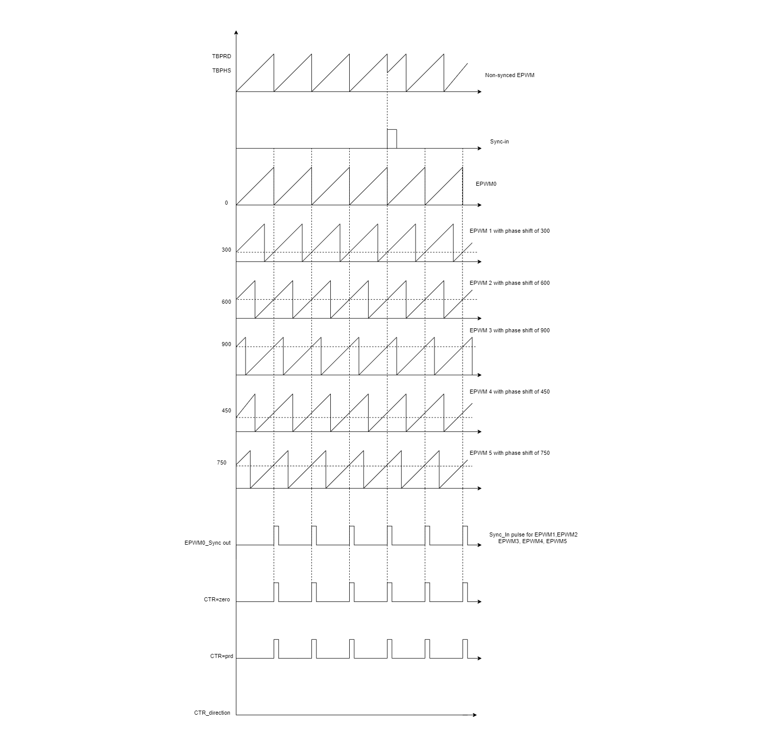
Waveform representation of phase shifted EPWM
Example Description
The example uses the following EPWMs to showcase the Synchronization features which includes:
- CONFIG_EPWM0 - This EPWM module is taken as the reference with 0 degree phase shift
- CONFIG_EPWM1 - This EPWM module is phase shifted by 300 TBCLK
- CONFIG_EPWM2 - This EPWM module is phase shifted by 600 TBCLK
- CONFIG_EPWM3 - This EPWM module is phase shifted by 900 TBCLK
- CONFIG_EPWM4 - This EPWM module is phase shifted by 450 TBCLK
- CONFIG_EPWM5 - This EPWM module is phase shifted by 750 TBCLK
- REF_CAPTURE - This ECAP module instance is used to capture falling edge event of EPWM0_A
- ECAP1_CAPTURE - This ECAP module instance is used to capture falling edge event of EPWM1_A
- ECAP2_CAPTURE - This ECAP module instance is used to capture falling edge event of EPWM2_A
- ECAP3_CAPTURE - This ECAP module instance is used to capture falling edge event of EPWM3_A
- ECAP4_CAPTURE - This ECAP module instance is used to capture falling edge event of EPWM4_A
- ECAP5_CAPTURE - This ECAP module instance is used to capture falling edge event of EPWM5_A
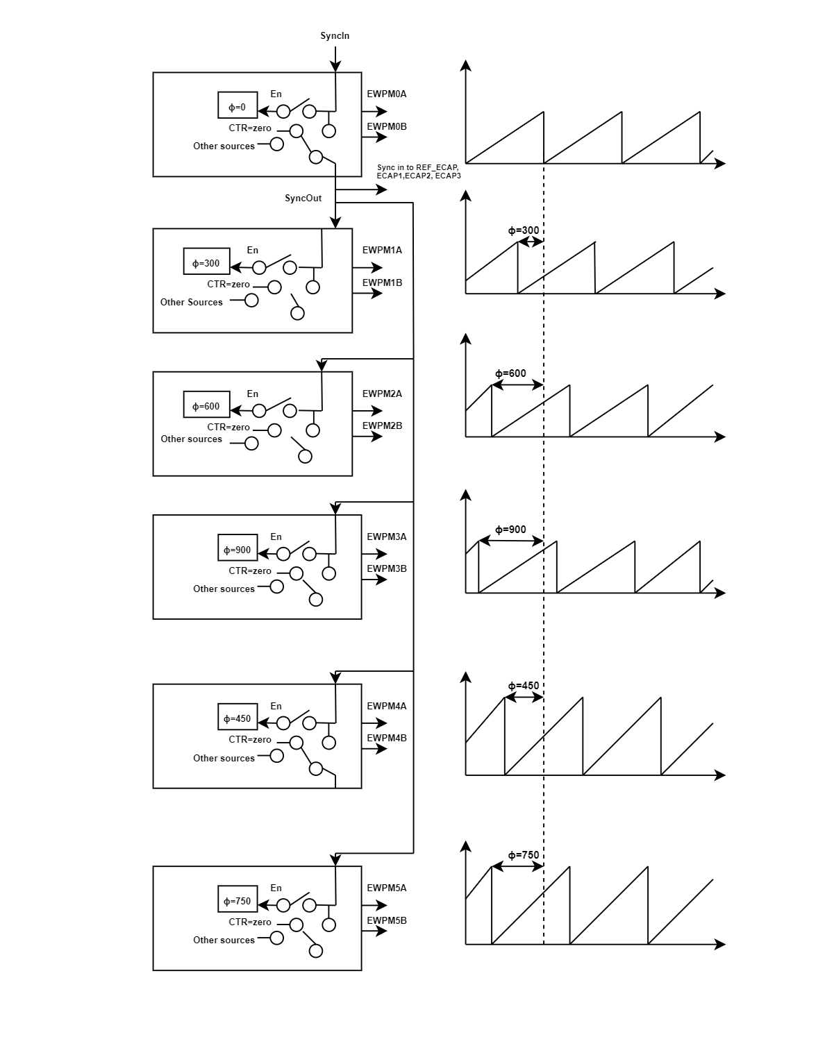
Block diagram of EPWM Synchronization
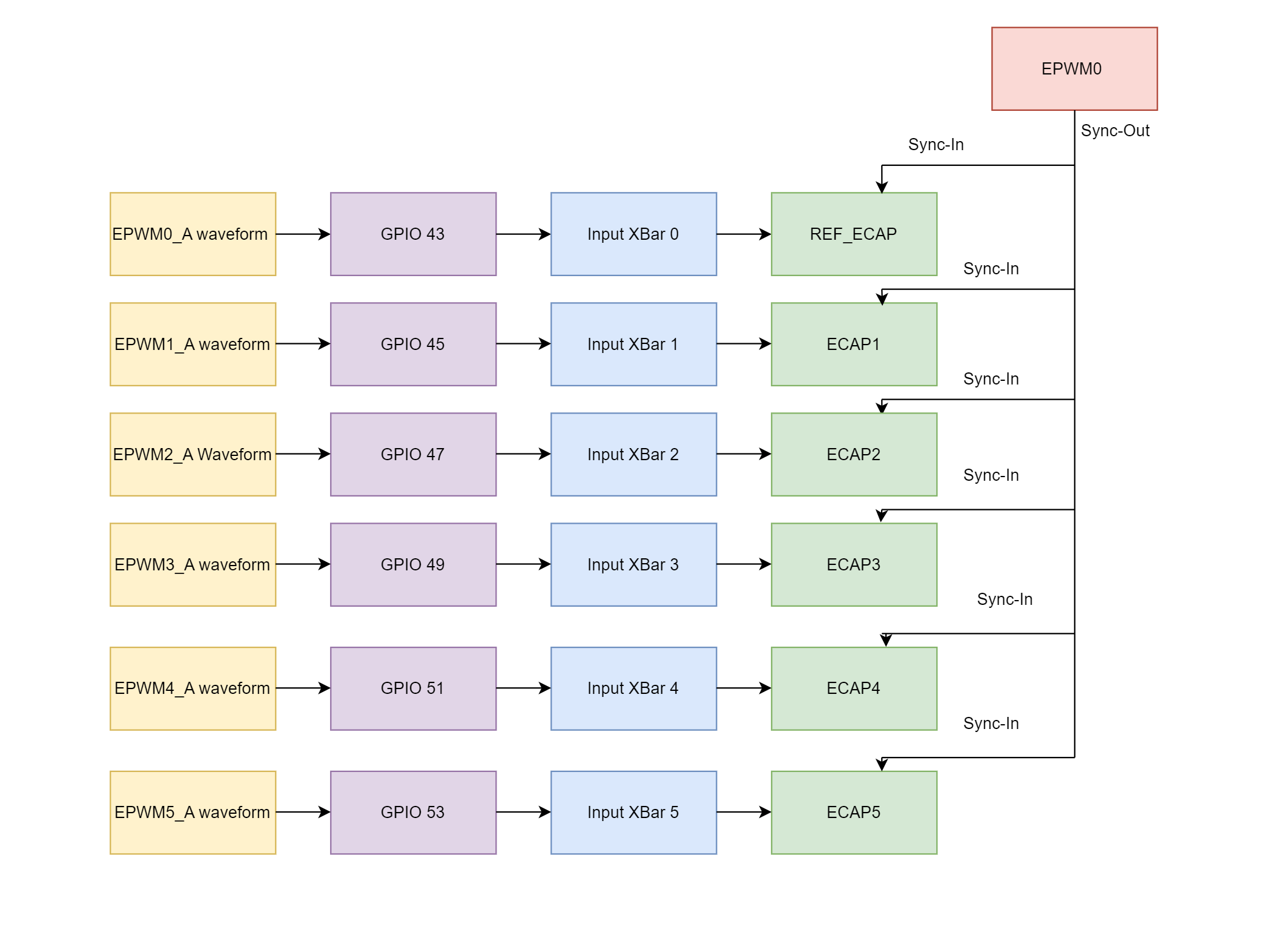
Integration of ECAP to capture EPWM waveform
External Connections
When using AM263x-CC with TMDSHSECDOCK (HSEC180 controlCARD Baseboard Docking Station) Probe the following
- CONFIG_EPWM0 output on HSEC PIN 49 (EPWM0_A)
- CONFIG_EPWM0 output on HSEC PIN 51 (EPWM0_B)
- CONFIG_EPWM1 output on HSEC PIN 53 (EPWM1_A)
- CONFIG_EPWM1 output on HSEC PIN 55 (EPWM1_B)
- CONFIG_EPWM2 output on HSEC PIN 50 (EPWM2_A)
- CONFIG_EPWM2 output on HSEC PIN 52 (EPWM2_B)
- CONFIG_EPWM3 output on HSEC PIN 54 (EPWM3_A)
- CONFIG_EPWM3 output on HSEC PIN 56 (EPWM3_B)
- CONFIG_EPWM4 output on HSEC PIN 57 (EPWM4_A)
- CONFIG_EPWM4 output on HSEC PIN 59 (EPWM4_B)
- CONFIG_EPWM5 output on HSEC PIN 61 (EPWM5_A)
- CONFIG_EPWM5 output on HSEC PIN 63 (EPWM5_B)
Early Access: For AM263Px-CC E1, the connections is same as that of AM263x
When using AM263X-LP
- CONFIG_EPWM0 output on J2.11 (EPWM0_A)
- CONFIG_EPWM0 output on J6.59 (EPWM0_B)
- CONFIG_EPWM1 output on J4.37 (EPWM1_A)
- CONFIG_EPWM1 output on J4.38 (EPWM1_B)
- CONFIG_EPWM2 output on J4.39 (EPWM2_A)
- CONFIG_EPWM2 output on J4.40 (EPWM2_B)
- CONFIG_EPWM3 output on J8.77 (EPWM3_A)
- CONFIG_EPWM3 output on J8.78 (EPWM3_B)
- CONFIG_EPWM4 output on J8.75 (EPWM9_A)
- CONFIG_EPWM4 output on J8.76 (EPWM9_B)
- CONFIG_EPWM5 output on J8.79 (EPWM13_A)
- CONFIG_EPWM5 output on J8.80 (EPWM13_B)
Supported Combinations
| Parameter | Value |
| CPU + OS | r5fss0-0 nortos |
| Toolchain | ti-arm-clang |
| Board | am263x-cc, am263x-lp |
| Example folder | examples/drivers/epwm/epwm_synchronization |
Steps to Run the Example
See Also
EPWM
Sample Output
Shown below is a sample output when the application is run,
EPWM Synchronization Test Started ...
EPWM Synchronization Example runs for 5 Secs
Falling Edge timestamp of Reference waveform : 1002
Falling Edge timestamp of EPWM1 : 702
Falling Edge timestamp of EPWM2 : 402
Falling Edge timestamp of EPWM3 : 102
Falling Edge timestamp of EPWM4 : 552
Falling Edge timestamp of EPWM5 : 252
Observed Phase Delay between Reference Waveform and EPWM1 Waveform : 300
Observed Phase Delay between Reference Waveform and EPWM2 Waveform : 600
Observed Phase Delay between Reference Waveform and EPWM3 Waveform : 900
Observed Phase Delay between Reference Waveform and EPWM4 Waveform : 450
Observed Phase Delay between Reference Waveform and EPWM5 Waveform : 750
EPWM Synchronization Test Passed!!
All tests have passed!!
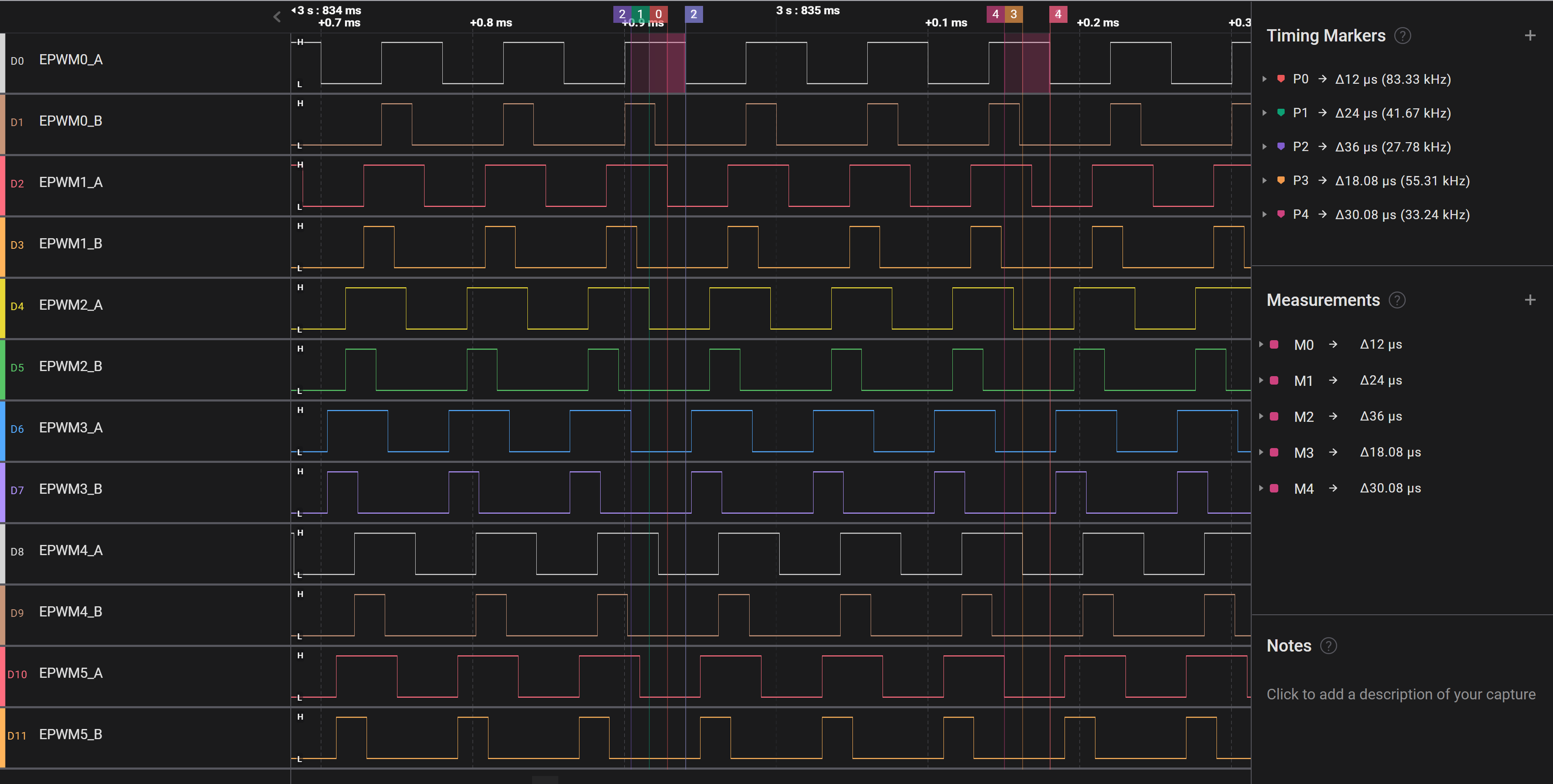
EPWM Synchronization Output Waveform


 1.8.20