Introduction
This example demostrates how the ECAP and ADC to be configured so that the ADC SOC can be triggered from the ECAP Events. The ECAP can trigger the ADC SOC Conversions in its both Capture mode and APWM mode.
- In ECAP Capture Mode, the CAPEVTx [x= 1 to 4] can be used and
- In ECAP APWM Mode, The counter match to Compare or Period can be used.
The example configures an ECAP (APWM_ECAP) to be in the APWM mode and generate an PWM waveform, and another ECAP (CAPTURE_ECAP) to be in Capture mode to recieve the PWM generated from the APWM_ECAP, via GPIO and InputXbar. Also, 2 ADCs ADC_APWM_TRIG, ADC_CAP_TRIG are configured to recieve triggers from the APWM_ECAP and CAPTURE_ECAP respectively. Both ADCs generate Interrupt at the EOCs and trigger respective App_adcISR. The ISRs are used for result reading and validation purpose of the example via incrementing a ISR count variable.
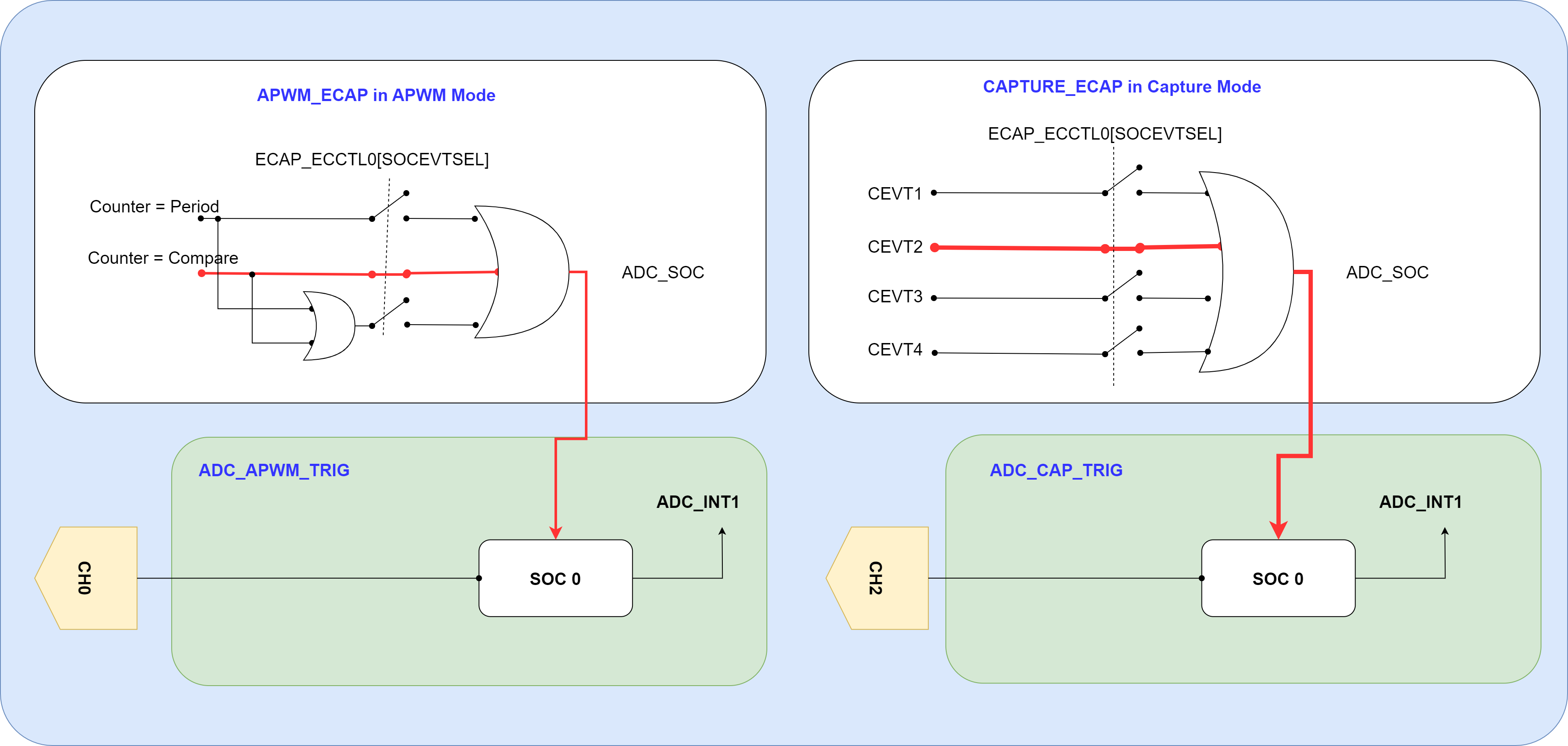
Example Block diagram
ECAP Configurations
- APWM_ECAP :
- generate a PWM wave of 5 KHz with 50% duty cycle.
- generate an ADC SOC trigger at its compare match (i.e, 5KHz triggers)
- CAPTURE_ECAP :
- recieve 2 edges, 1 rising then 1 falling (CAPEVT1,2)
- generate an ADC SOC trigger at CAPEVT2
ADC Configurations
ADC_APWM_TRIG (or ADC_CAP_TRIG) :
- SOC 0 is configured to recieve trigger from the APWM_ECAP (or CAPTURE_ECAP)
- INT 1 is generated at the EOC/SOC0
- Prescaled at 3, with Sample and Hold window of 18, configuring for 4MSPS on ADC.
ISRs
App_apwmTrigAdcISR (or App_capTrigAdcISR)
- ADC INT 1 from ADC_APWM_TRIG (or ADC_CAP_TRIG) is configured via INTxBar to trigger App_apwmTrigAdcISR (or App_capTrigAdcISR).
- Each ISR reads the respective SOC result, clears the ADC INT flags and Increments a counter for validation.
External Connections
AM263x-CC E2 or AM263Px-CC E2 :
Feed Analog voltages on ADC_APWM_TRIG (ADC0)
- ADC0_AIN2, i.e., HSEC PIN 15 Feed Analog voltages on ADC_CAP_TRIG (ADC1)
- ADC1_AIN0, i.e., HSEC PIN 12
AM263x-LP :
Feed Analog voltages on ADC_APWM_TRIG (ADC0)
- ADC0_AIN2, i.e., J5/7 PIN 66 Feed Analog voltages on ADC_CAP_TRIG (ADC1)
- ADC1_AIN0, i.e., J1/3 PIN 24
Watch Variables
The below watch variables can be used to view ADC conversion results.
- gApwmTrigAdcResult[] : Digital representation of the voltage sample on pin AIN2 of ADC_APWM_TRIG
- gCapTrigAdcResult[] : Digital representation of the voltage sample on pin AIN0 of ADC_CAP_TRIG
Supported Combinations
| Parameter | Value |
| CPU + OS | r5fss0-0 nortos |
| Toolchain | ti-arm-clang |
| Board | am263x-cc, am263x-lp |
| Example folder | examples/drivers/adc/adc_soc_ecap/ |
Steps to Run the Example
- When using CCS projects to build, import the CCS project for the required combination and build it using the CCS project menu (see Using SDK with CCS Projects).
- When using makefiles to build, note the required combination and build using make command (see Using SDK with Makefiles)
- Establish connections as mentioned in External Connections section
- Launch a CCS debug session and run the executable, see CCS Launch, Load and Run
- Using watch variables, view the ADC conversion results.
- View the ADC conversion results in UART console logs
See Also
ADC
Sample Output
Shown below is a sample output when the application is run,
ADC Triggered by ECAP Test Started ...
ADC Triggered by ECAP Test Passed
All tests have passed!!


 1.8.20