|
AM263x MCU+ SDK
08.04.00
|


|
|
AM263x MCU+ SDK
08.04.00
|
|
The flash driver in the SDK is supposed to work based on a configuration structure passed on the driver during the initialization time. This configuration structure has been chosen to support the configuration models of a number of flashes from multiple vendors. Currently, this configuration is generated by SysConfig from the options provided in the SysConfig Flash Module. This guide details the steps to bring up a custom flash using these tools and methods provided in the SDK. In a later version a method will be provided to do this without SysConfig as well.
The QSPI interface present in the SOC can support only the 1S-1S-1S mode or the 1S-1S-4S modes for reading from the flash.
The configuration structure can be obtained albeit automatically if the flash supports SFDP (Serial Flash Discoverable Parameter) table.
The Serial Flash Discoverable Parameters (SFDP) is a standard which provides a consistent method of describing the functional and feature capabilities of the flash device in a standard set of internal parameter tables. This table can be queried to identify the configurations and adjustments needed to set the flash in a desired state.
The parsing of the SFDP table is time consuming. Considering this, the SFDP parsing feature in this SDK is tied with a diagnostic example of the QSPI driver. In flashes where the SFDP is supported, this example can be used to parse the details into a config structure which can aid bringing up the custom flash. As of now the SFDP parsing in the SDK supports upto JEDS216D standard.
qspi_flash_diag example : QSPI Flash Diag. This example communicates with the flash in 1S-1S-1S mode and queries the flash for the SFDP table (if SFDP is supported by the flash) among other things. The logs from this example would be required later to configure the flash driver.qspi_flash_diag log. Save this SysConfig configuration.Now you can test your example/application with the new flash device! Also test the configuration with QSPI bootloader SBL QSPI and flash writer SBL UART Uniflash by flashing an example Flash a Hello World example. Let's get into the details of the steps.
Refer the example page QSPI Flash Diag on building this application.
You will need have to initialize the SOC in no boot mode as mentioned in SOC Initialization Using CCS Gels and also load and run this example using CCS, as mentioned in CCS Launch, Load and Run.
Building and running the QSPI Flash Diagnostic example is important because regardless of flash supporting SFDP or not, the diagnostic example gives a basic sanity for the flash. If the flash diagnostic doesn't work, there could be HW connection issues most probably. When you successfully build and run the example, you should get a log with json data like this:
You will see this if your flash supports SFDP. In this case, copy this part save it as JSON file, this would be useful in Step 2. In fact, the TI Board Default Flash configuration is also saved as json.
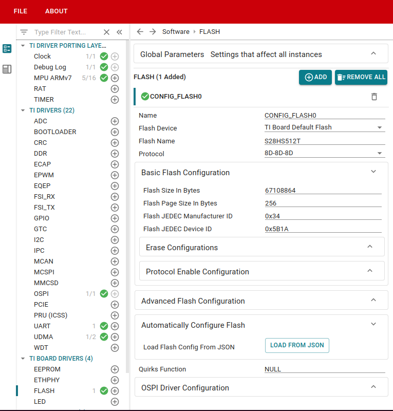
As you can see in the above image, there are various configurations options available for the flash.
Flash Device as custom flash instead of TI Board Default Flash.Rest of the configuration depends on whether the flash supports SFDP or not.
If your flash supports SFDP and the qspi_flash_diag example is able to print out the SFDP table as shown in Step 1, configuring the flash in your example via SysConfig is quite easy.
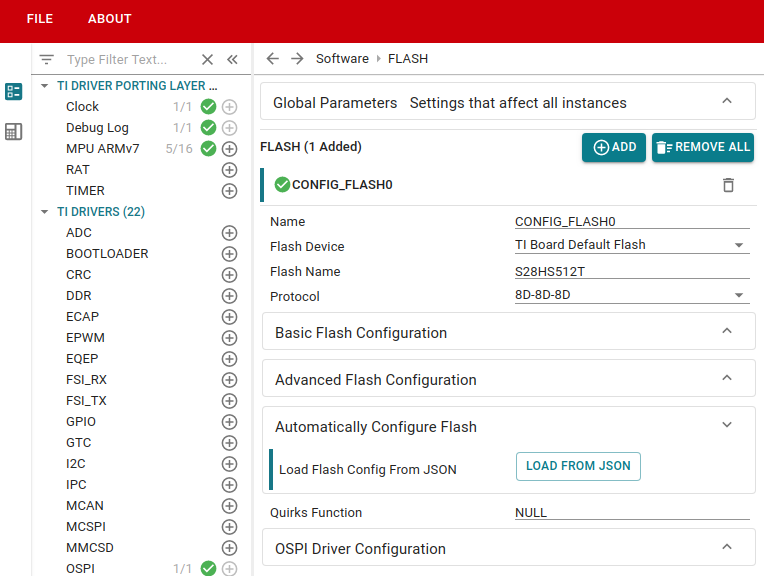
LOAD FROM JSON button which will open a file dialog.If your flash doesn't support SFDP, the flash configuration details would need to be filled in manually. This can be a pain point, but mostly flashes without SFDP support wouldn't have a lot of configuration as well. Only basic things like quad bit enable, etc would need to be looked up in the datasheet.
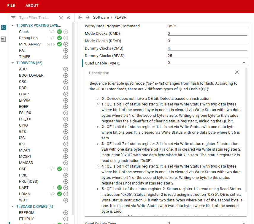
Most of the configurables should be self explanatory. Still if some terms seem confusing, look for a question mark icon near the configurable when you hover. Clicking on that should give the long description regarding a certain configurable.
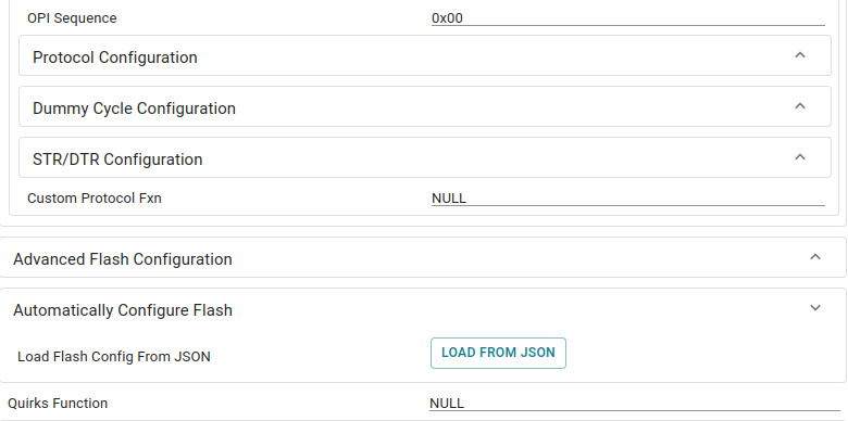
We have tried to keep an interface as generic as possible. But because of the variety of flash vendors and configurations, sometimes setting a protocol might differ from the sequences listed in SysConfig interface. Sometimes there might be extra steps required during the initialization for the flash to function correctly. To tackle this issue, we have given the option of two hooks:
The custom protocol hook will be invoked in the middle of the Flash_open function and the quirks function will be invoked at the end of the Flash_open function.
You would find these options in the SysConfig GUI for flash under the protocol configuration after you've selected your protocol as __"Custom Protocol"__. The quirks function is always present as the last configurable.
You should leave these as NULL if your flash doesn't need this.
This section can be ignored if the flash supports SFDP.
All the details regarding the flash including fast read opcodes, supported erase sizes, dummy clocks needed for each instruction and flash configuration registers information will be available from the flash data sheet.
 1.8.20