Introduction
This example uses the ePWM to generate a PWM signal.
The example does the below
- Configures ePWM to generate the signal with a specified frequency and duty cycle.
- Waits for the specified time using ePWM ISR.
External Connections
- EPWM9_A/B pin can be connected to an oscilloscope to view the waveform.
AM263X-CC
When using AM263x-CC with TMDSHSECDOCK (HSEC180 controlCARD Baseboard Docking Station)
- Connect FSI header (on ControlCard) pin 8 for epwm9_A
- Connect FSI header (on ControlCard) pin 1 for epwm9_B
AM263X-LP
When using AM263x-LP
- Connect boosterpack J6/J8 pin 75 for epwm9_A
- Connect boosterpack J6/J8 pin 76 for epwm9_B
Supported Combinations
| Parameter | Value |
| CPU + OS | r5fss0-0 nortos |
| Toolchain | ti-arm-clang |
| Board | am263x-cc, am263x-lp |
| Example folder | examples/drivers/epwm/epwm_hr_duty_cycle/ |
Steps to Run the Example
- When using CCS projects to build, import the CCS project for the required combination and build it using the CCS project menu (see Using SDK with CCS Projects).
- When using makefiles to build, note the required combination and build using make command (see Using SDK with Makefiles)
- Establish connections as mentioned in External Connections section
- Launch a CCS debug session and run the executable, see CCS Launch, Load and Run
See Also
EPWM
Sample Output
Shown below is a sample output when the application is run,
EPWM Duty Cycle Test Started ...
App will wait for 60 seconds (using PWM period ISR) ...
EPWM Duty Cycle Test Passed!!
All tests have passed!!
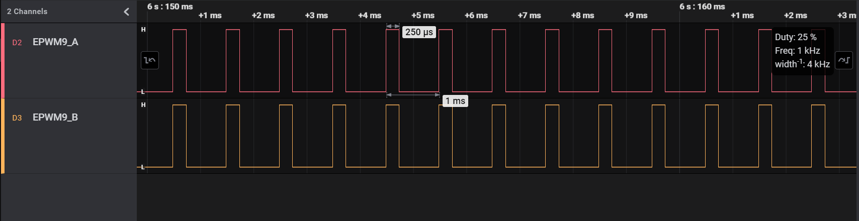
EPWM HR duty cycle waveform


 1.8.20