Introduction
EPWM Valley Switching
This example configures ePWM0 as follows
- ePWM0 with DCAEVT1 forcing the ePWM output LOW
- GPIO48 is used as the input to the INPUT XBAR INPUT1
- INPUT1 (from INPUT XBAR) is used as the source for DCAEVT1
- GPIO122 is set to output and toggled in the main loop to trip the PWM
- ePWM0 with DCBEVT1 forcing the ePWM output LOW
- GPIO48 is used as the input to the INPUT XBAR INPUT1
- INPUT1 (from INPUT XBAR) is used as the source for DCBEVT1
- GPIO122 is set to output and toggled in the main loop to trip the PWM
- DCBEVT1 uses the filtered version of DCBEVT1
- The DCFILT signal uses the valley switching module to delay the
- DCFILT signal by a software defined DELAY value.
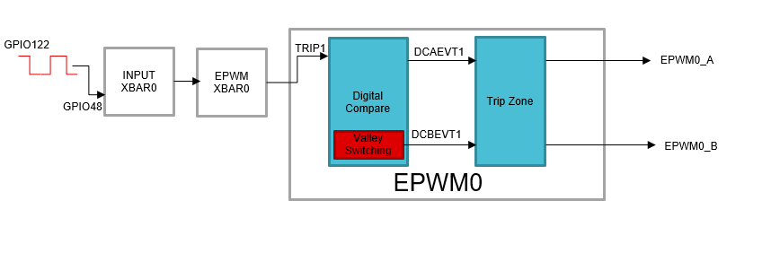
Block Diagram for EPWM Valley Switching example
External Connections
- GPIO48 is connected to GPIO122.
- EPWM0_A and EPWM0_B pin can be connected to an oscilloscope to view the waveform.
AM263X-CC
When using AM263x-CC with TMDSHSECDOCK (HSEC180 controlCARD Baseboard Docking Station)
- Connect HSEC Pin 52 to HSEC Pin 74
- Capture waveform on HSEC Pin 49 for epwm0_A
- Capture waveform on HSEC Pin 51 for epwm0_B
AM263X-LP
Supported Combinations
| Parameter | Value |
| CPU + OS | r5fss0-0 nortos |
| Toolchain | ti-arm-clang |
| Board | am263x-cc, am263x-lp |
| Example folder | examples/drivers/epwm/epwm_valley_switching |
Steps to Run the Example
- When using CCS projects to build, import the CCS project for the required combination and build it using the CCS project menu (see Using SDK with CCS Projects).
- When using makefiles to build, note the required combination and build using make command (see Using SDK with Makefiles)
- Establish connections as mentioned in External Connections section
- Launch a CCS debug session and run the executable, see CCS Launch, Load and Run
See Also
EPWM
Sample Output
Shown below is a sample output when the application is run,
EPWM Valley Switching Test Started ...
EPWM Valley Switching Test Passed!!
All tests have passed!!
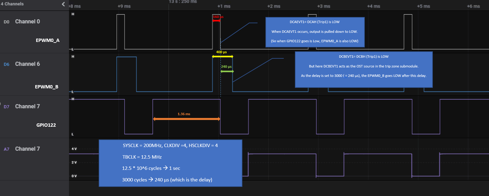
EPWM Valley Switching waveform


 1.8.20