Introduction
EPWM HR UpDown
This example modifies the MEP control registers to show edge displacement for high-resolution period with ePWM in Up-Down count mode due to the HRPWM control extension of the respective ePWM module.
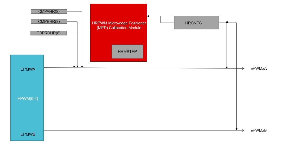
Block Diagram for EPWM HR UpDown example
External Connections
- Pin can be connected to high resolution oscilloscope (1 GHz) to observe the edge displacement.
AM263X-CC
When using AM263x-CC with TMDSHSECDOCK (HSEC180 controlCARD Baseboard Docking Station)
- Capture waveform on HSEC Pin 49, 51 for epwm0
- Capture waveform on HSEC Pin 53, 55 for epwm1
- Capture waveform on HSEC Pin 50, 52 for epwm2
- Capture waveform on HSEC Pin 54, 56 for epwm3
- Capture waveform on HSEC Pin 57, 59 for epwm4
AM263X-LP
Supported Combinations
| Parameter | Value |
| CPU + OS | r5fss0-0 nortos |
| Toolchain | ti-arm-clang |
| Board | am263x-cc, am263x-lp |
| Example folder | examples/drivers/epwm/epwm_hr_updown |
Steps to Run the Example
- When using CCS projects to build, import the CCS project for the required combination and build it using the CCS project menu (see Using SDK with CCS Projects).
- When using makefiles to build, note the required combination and build using make command (see Using SDK with Makefiles)
- Establish connections as mentioned in External Connections section
- Launch a CCS debug session and run the executable, see CCS Launch, Load and Run
See Also
EPWM
Sample Output
Shown below is a sample output when the application is run,
EPWM High Resolution Up Down Test Started ...
EPWM High Resolution Up Down Test Passed!!
All tests have passed!!
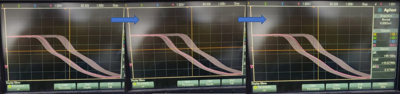
EPWM HR UpDown waveform


 1.8.20