AM263x MCU+ SDK  08.02.00
EPWM DMA

Introduction

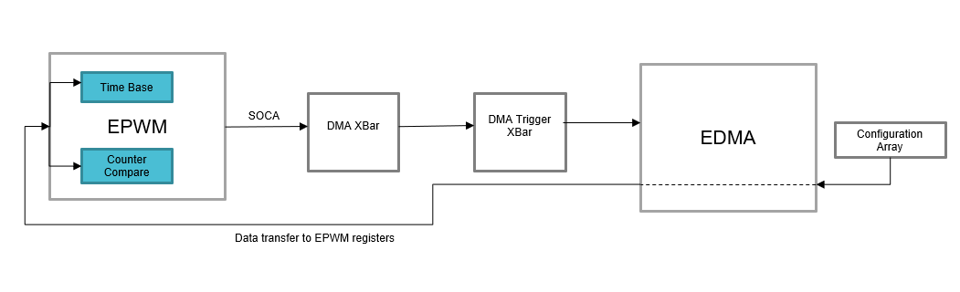
This example configures ePWM0 and DMA as follows:

  • ePWM0 is set up to generate PWM waveforms
  • DMA channel 0 is set up to update the CMPAHR, CMPA, CMPBHR and CMPB every period with the next value in the configuration array. This allows the user to create a DMA enabled fifo for all the CMPx and CMPxHR registers to generate unconventional PWM waveforms.
  • DMA channel 1 is set up to update the TBPHSHR, TBPHS, TBPRDHR and TBPRD every period with the next value in the configuration array.
  • Other registers such as AQCTL can be controlled through the DMA as well by following the same procedure.

Block Diagram for EPWM DMA example

External Connections

EPWM0_A/B pin can be connected to an oscilloscope to view the waveform.

AM263X-CC

When using AM263x-CC with TMDSHSECDOCK (HSEC180 controlCARD Baseboard Docking Station)

  • Capture waveform on HSEC Pin 49 for epwm0_A
  • Capture waveform on HSEC Pin 51 for epwm0_B

AM263X-LP

Supported Combinations

Parameter Value
CPU + OS r5fss0-0 nortos
Toolchain ti-arm-clang
Board am263x-cc, am263x-lp
Example folder examples/drivers/epwm/epwm_dma

Steps to Run the Example

See Also

EPWM

Sample Output

Shown below is a sample output when the application is run,

EPWM DMA Test Started ...
EPWM DMA Test Passed!!
All tests have passed!!