|
AM243x MCU+ SDK
08.04.00
|


|
|
AM243x MCU+ SDK
08.04.00
|
|
Tamagawa diagnostic application does below,
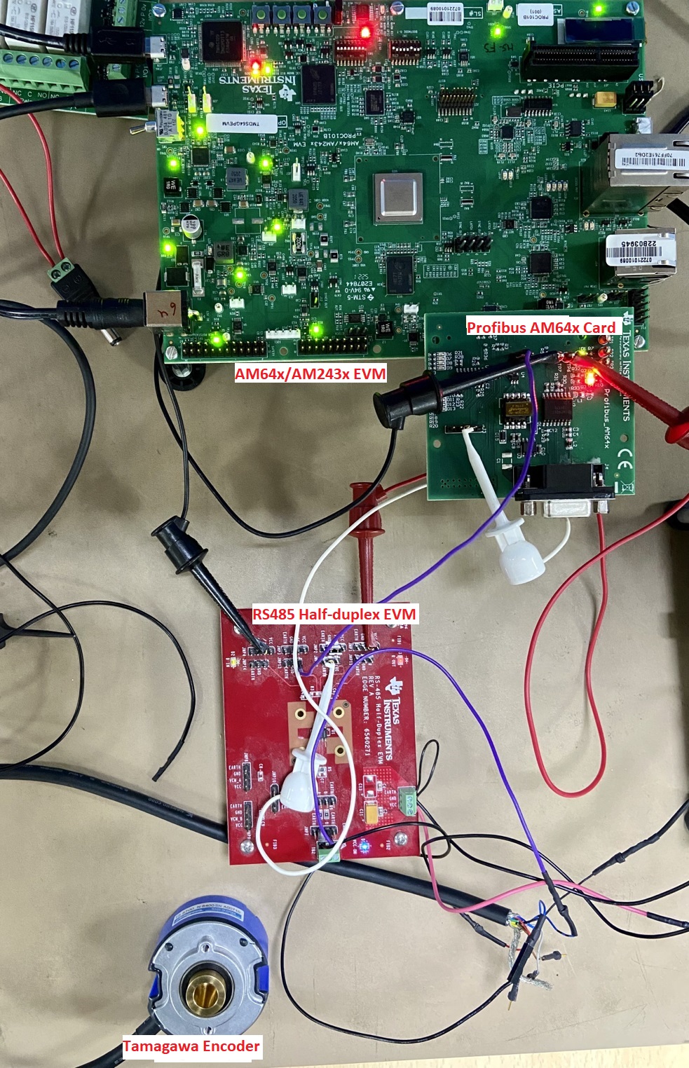
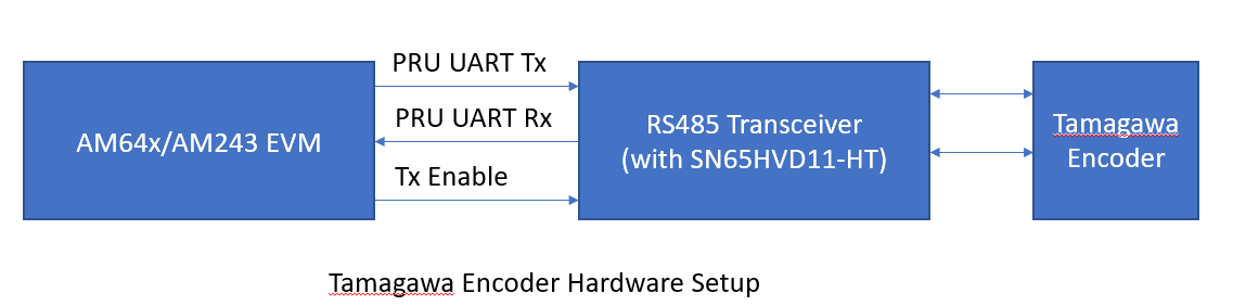
Configures pinmux, GPIO, UART, ICSS clock to 200MHz, Initializes ICSS0-PRU1, Loads the initialization section of PRU firmware & executes it. This application is controlled with a terminal interface using a serial over USB connection between the PC host and the EVM. Please connect a USB cable between the PC and the EVM. A serial terminal application (like teraterm/ hyperterminal/ minicom) is then run on the host. To configure, select the serial port corresponding to the port emulated over USB by the EVM. The host serial port should be configured to 115200 baud, no parity, 1 stop bit and no flow control. Connect the Tamagawa encoder via RS485 transceiver to the EVM. The connections between EVM and RS485 logic signals are:
PRU UART Rx -> PRG0_PRU1_GPO9 PRU UART Tx -> PRG0_PRU1_GPO10 Tx Enable -> PRG0_PRU1_GPO0 It is necessary to provide 3.3V to the RS485 logic side. The receive transceiver is always kept enabled with bus side connected as in Tamagawa Specification.
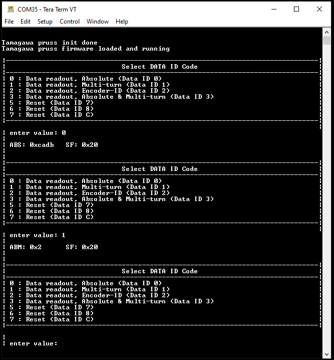
The Tamagawa receiver firmware running on ICSS0-PRU1 provides a defined interface. The Tamagawa diagnostic application interacts with the Tamagawa receiver firmware interface. It then presents the user with menu options to select Data ID code (as defined by Tamagawa) to be sent to the encoder. The application collects the data entered by the user and configures the relevant interface. Then via the Tamagawa receiver interface, the command is triggered. Once the command completion is indicated by the interface, the status of the transaction is checked. If the Status indicates success, the result is presented to the user.
| Folder/Files | Description |
|---|---|
| ${SDK_INSTALL_PATH}/examples/motor_control/tamagawa_diagnostic | |
| tamagawa_diagnostic.c | Tamagawa diagnostic application |
| ${SDK_INSTALL_PATH}/source/motor_control/position_sense/tamagawa | |
| firmware/ | Folder containing TAMAGAWA PRU firmware sources. |
| Parameter | Value |
|---|---|
| CPU + OS | r5fss0-0 freertos |
| ICSSG | ICSSG0 |
| PRU | PRU1 |
| Toolchain | ti-arm-clang |
| Board | am243x-evm |
| Example folder | examples/motorcontrol/tamagawa_example |
Shown below is a sample output when the application is run:
| Data_ID | Name | Description |
|---|---|---|
| Data ID 0 | Data readout (absolute position data) | In this command we will receive: Absolute rotor position value in field name ABS.. Errors and warnings in field name SF(status field) |
| Data ID 1 | Data readout (multi-turn data) | In this command we will receive data about: No. of rotor turns in field name ABM. Errors and warnings in field name SF(status field). |
| Data ID 2 | Endoder-ID | In this command we will receive data about : Tamagawa encoder make-ID in ENID field . Errors and warnings in field name SF(status field) |
| Data ID 3 | Data readout(absolute+multiturn+encoder-ID) | In this command we will receive : Absolute rotor position value in field name ABS. No. of rotor turns in field name ABM. Tamagawa encoder make-ID in ENID field . Errors and warnings in field name SF(status field) Other warnings in field name ALMC |
| Data ID 5 | Reset-Error | This command used to reset errors. |
| Data ID 6 | Reset- absolute | This command used to reset absolute position data(ABS) |
| Data ID 7 | Reset- multiturn | This command used to reset multi-turn data(ABM) |
 1.8.20