|
AM243x MCU+ SDK
08.04.00
|


|
|
AM243x MCU+ SDK
08.04.00
|
|
The HDSL diagnostic application described here interacts with the firmware interface.
HDSL diagnostic application does below,
Firmware is split to three sections, initialization, datalink and transport. At startup, the application displays details about encoder and status. It then presents the user with menu options, based on the option selected, application communicates with HDSL interface and the result is presented to the user.
| Folder/Files | Description |
|---|---|
| ${SDK_INSTALL_PATH}/examples/motor_control/hdsl_diagnostic | |
| hdsl_diagnostic.c hdsl_diagnostic.h | Source and Header files |
| ${SDK_INSTALL_PATH}/source/motor_control/position_sense/hdsl | |
| driver/ | Folder containing HDSL PRU driver sources. |
| include/ | Folder containing HDSL PRU header sources. |
| firmware/ | Folder containing HDSL PRU firmware sources. |
| Parameter | Value |
|---|---|
| CPU + OS | r5fss0-0 freertos |
| ICSSG | ICSSG0 |
| PRU | PRU1 |
| Toolchain | ti-arm-clang |
| Board | am243x-evm |
| Example folder | examples/motorcontrol/hdsl_example |
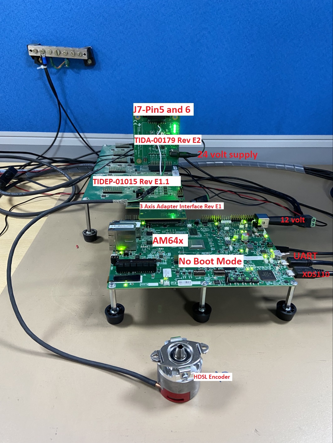
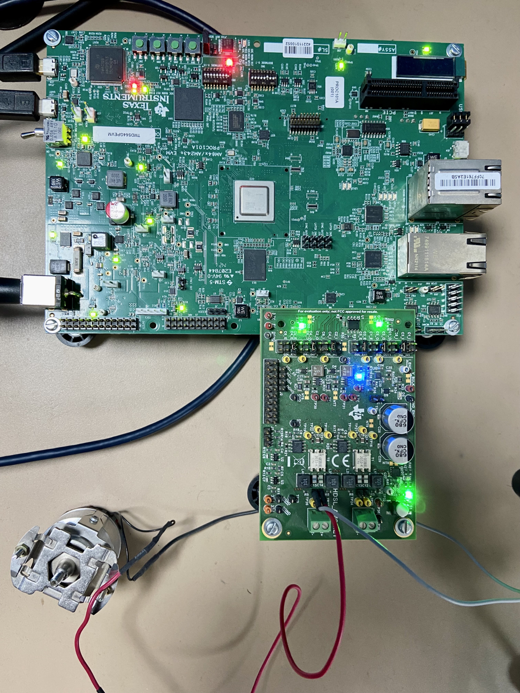
Other than the basic EVM setup mentioned in EVM Setup, below additional HW is required to run this demo
This is a test feature, in real application - PWM syncout will be connected to Latch input instead of IEP1 sync.
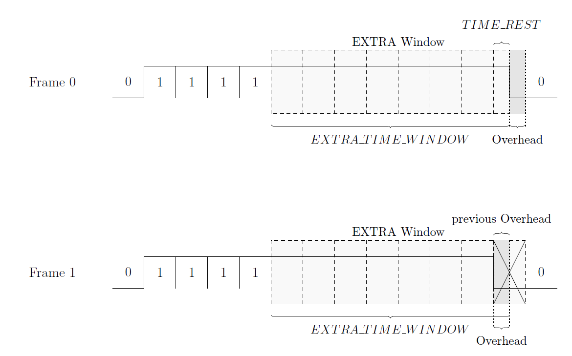
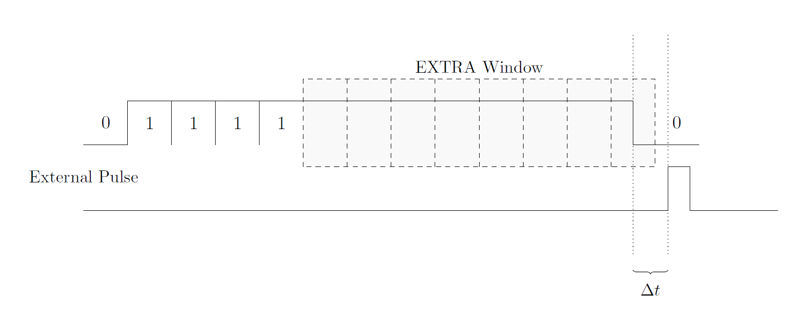
According to the Hiperface DSL specification, the falling edge inside the EXTRA window should coincide with the external synchronization pulse. At the beginning of the startup phase, the firmware measures the time interval of the external pulse and calculates the required number of bits for the H-Frame. Based on this number the stuffing length and EXTRA window size is derived. Afterwards, the PRU waits to match its timing with the timing of the external synchronization pulse and starts the transmission. Since it is possible to use time intervals for the external pulse that are not multiples of the bit duration, the firmware needs to adjust the H-Frame size on the fly. Furthermore, during the EXTRA window the PRU transmits the data (sample edge) with a granularity of 13.3ns to increase the synchronization accuracy. Figure "Synchronization of External Pulse with Sample Edge in EXTRA Window" and "Illustration of Synchronization Algorithm" depict the concept. The EXTRA_TIME_WINDOW is a fixed value that is calculated at startup to match the external pulse frequency. The TIME_REST value gives the number of overclocked ‘1’ that needs to be sent during the last bit of the EXTRA window.
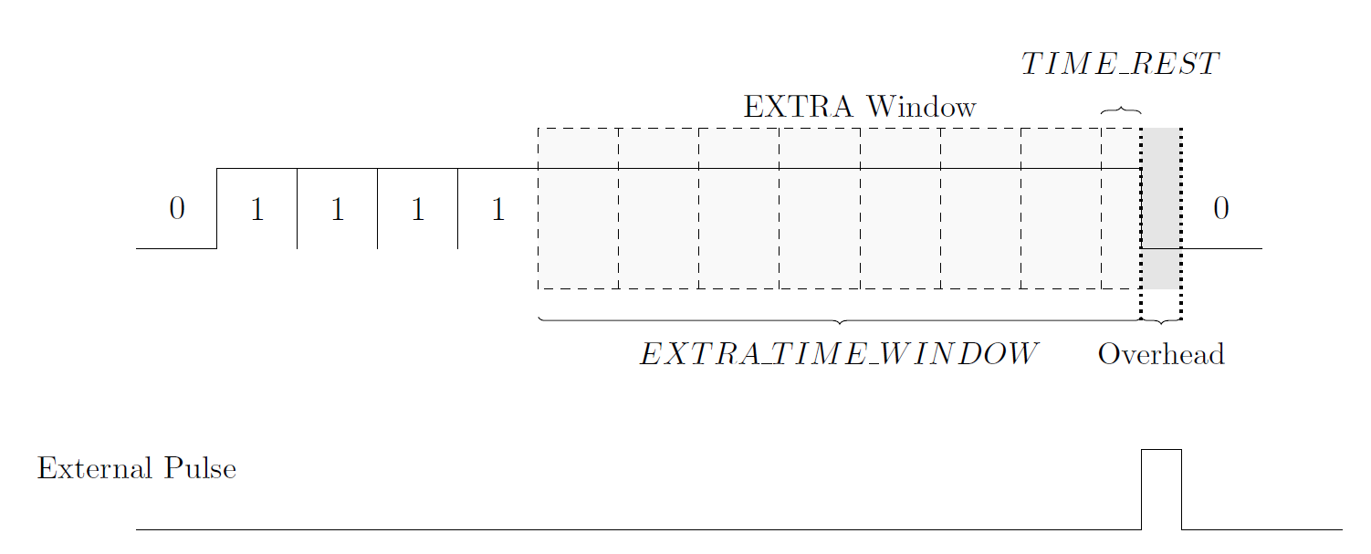
In other words, the TIME_REST value represents the sample edge in a fine granularity dimension (13.3ns). While the sample edge can be send with a finer granularity, the granularity of the size of the EXTRA window is still in whole bit durations (106.67ns). Consequently, there is an overhead, if the external pulse period is not a multiple of the bit duration. This overhead is compensated in the next H-Frame by changing the size of the EXTRA window. As a result, the size of the H-Frame is varying over time. It is possible that these calculations lead to the excess of the maximum or minimum EXTRA window size. Therefore, the number of bits for the stuffing and EXTRA window is readjusted on a violation.
The algorithm is given as C code in the following:
        /* EXTRA_SIZE equals the number of bits for the EXTRA window minus 1 */
        if(EXTRA_EDGE == 0)
            TIME_REST += 8;
        short b = (EXTRA_SIZE << 3) + TIME_REST;
        short overhead = (EXTRA_SIZE << 3) + 8 - TIME_EXTRA_WINDOW;
        EXTRA_SIZE = (b - overhead) >> 3;
        TIME_REST = (b - overhead) - (EXTRA_SIZE << 3);

        if(EXTRA_SIZE < 3) {
            EXTRA_SIZE += 6;
            NUM_STUFFING -= 1;
            TIME_EXTRA_WINDOW += (8*6);
        }
if(EXTRA_SIZE > 8) { EXTRA_SIZE -= 6; NUM_STUFFING += 1; TIME_EXTRA_WINDOW -= (8*6); }
EXTRA_EDGE represents the TIME_REST value in a format that can be pushed to the TX FIFO for transmission. For instance, if TIME_REST is 4, EXTRA_EDGE is 0xf0. The edge would be in the middle of the bit duration. The value NUM_STUFFING gives the number of stuffing blocks (each block consist of 6 bits).
For further improvement of the synchronization, the time difference (∆t) between the external pulse and the sample edge we transmit is measured (Figure "Time difference between External Pulse and Sample Edge").
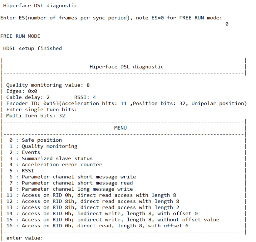
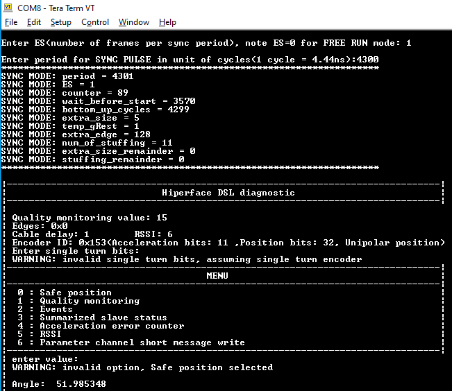
Shown below is a sample output when the application is run:
 1.8.20