|
AM243x MCU+ SDK
08.04.00
|


|
|
AM243x MCU+ SDK
08.04.00
|
|
The EnDat diagnostic application, described here, demonstrates the EnDat master operation.
The EnDat driver provides a well defined set of API's to expose EnDat master interface.
The diagnostic invokes these API's to
Once these steps are executed,
Once initial setup is over,
After the user selects an EnDat command,
| Folder/Files | Description |
|---|---|
| ${SDK_INSTALL_PATH}/examples/motor_control/endat_diagnostic | |
| endat_diagnostic.c | EnDAT diagnostic application |
| ${SDK_INSTALL_PATH}/source/motor_control/position_sense/endat | |
| firmware/ | Folder containing EnDAT firmware sources. |
| driver/ | EnDAT diagnostic driver. |
| Parameter | Value |
|---|---|
| CPU + OS | r5fss0-0 freertos |
| ICSSG | ICSSG0 |
| PRU | PRU1 |
| Toolchain | ti-arm-clang |
| Board | am243x-evm |
| Example folder | examples/motorcontrol/endat_example |
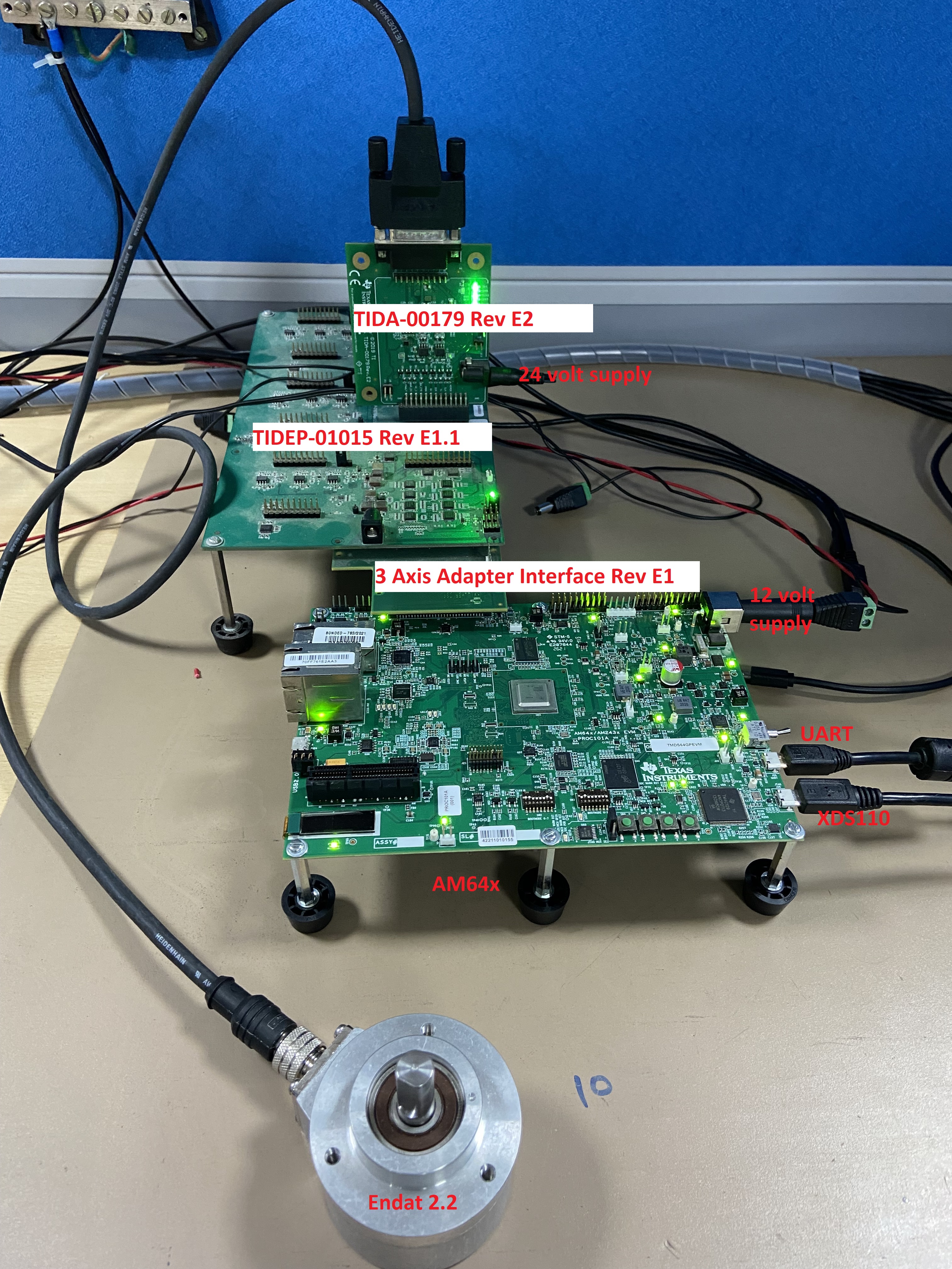
Other than the basic EVM setup mentioned in EVM Setup, below additional HW is required to run this demo
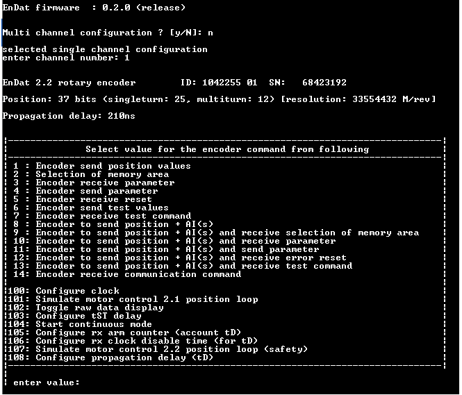
Shown below is a sample output when the application is run:
| Test detail | Steps | Pass/fail crieteria |
|---|---|---|
| To check position value | 1. Selct Single channel mode from UART menu | |
| 2. Enter 0 to select channel 0 | ||
| 3. Enter 1 to select "Encoder send position values" | Crc success | |
| To receive encoder's operating parameters(error messege) | 1. Selct Single channel mode from UART menu | |
| 2. Enter 0 to select channel 0 | ||
| 3. Enter 2 to select "Selection of memory area" | Crc success | |
| 4. Enter "B9" in MRS code to select "Operating parameters" | Crc success | |
| 5. Enter 4 to select "Encoder to send parameter" | Crc success | |
| 6. Enter 0 in "parameter address" for selecting "Error message" | Crc success | |
| To receive encoder's manufacture parameters for Endat 2.2 | 1. Selct Single channel mode from UART menu | |
| 2. Enter 0 to select channel 0 | ||
| 3. Enter 2 to select "Selection of memory area" | Crc success | |
| 4. Enter "BD" in MRS code to select "Parameters of encoder manufacturer for Endat 2.2" | Crc success | |
| 5. Enter 4 to select "Encoder to send parameter" | Crc success | |
| 6. Enter 0 in "parameter address" for selecting "Status of additional info" | Crc success | |
| To set values to encoder's operating parameters (error message) | 1. Selct Single channel mode from UART menu | |
| 2. Enter 0 to select channel 0 | ||
| 3. Enter 2 to select "Selection of memory area" | Crc success | |
| 4. Enter "B9" in MRS code to select "Operating parameters" | Crc success | |
| 5. Enter 3 to select "Encoder to receive parameter" | Crc success | |
| 6. Enter 0 in "parameter address" for selecting "Error message" | Crc success | |
| 7. Enter 0 in "parameter value" for seting value in " Error message" | Crc success | |
| To set values to encoder's manufacturing parameters for Endat 2.2(Status of additional info) | 1. Selct Single channel mode from UART menu | |
| 2. Enter 0 to select channel 0 | ||
| 3. Enter 2 to select "Selection of memory area" | Crc success | |
| 4. Enter "BD" in MRS code to select "Parameters of encoder manufacturer for Endat 2.2" | Crc success | |
| 5. Enter 3 to select "Encoder to receive parameter" | Crc success | |
| 6. Enter 0 in "parameter address" for selecting "Status of additional info" | Crc success | |
| 7. Enter 0 in "parameter value" for seting value in " Status of additional info" | Crc success | |
| To reset encoder | 1. Selct Single channel mode from UART menu | |
| 2. Enter 0 to select channel 0 | ||
| 3. Enter 5 to select "Encoder receive reset" | Crc success | |
| To receive test values from encoder with port address "0" | 1. Selct Single channel mode from UART menu | |
| 2. Enter 0 to select channel 0 | ||
| 3. Enter 7 to select "Encoder receive test command" | ||
| 4. Enter 0 in "enter port address" | ||
| 5. Enter 6 to select "Encoder send test values" | Crc success | |
| To receive test values from encoder with port address "E" | 1. Selct Single channel mode from UART menu | |
| 2. Enter 0 to select channel 0 | ||
| 3. Enter 7 to select "Encoder receive test command" | ||
| 4. Enter "E" in "enter port address" | ||
| 5. Enter 6 to select "Encoder send test values" | Crc success | |
| To check position value with aditional info. | 1. Selct Single channel mode from UART menu | |
| 2. Enter 0 to select channel 0 | ||
| 3. Enter 8 to select "Encoder send position values + AI(s)" | Crc success | |
| To receive encoder's operating parameters(error messege) +receive position value with additional info | 1. Selct Single channel mode from UART menu | |
| 2. Enter 0 to select channel 0 | ||
| 3. Enter 9 to select "Encoder send position values + AI(s) and Selection of memory area" | ||
| 4. Enter "B9" in MRS code to select "Operating parameters" | some time MRS code selection Failure | |
| 5. Enter 11 to select "Encoder send position values + AI(s) and send parameter" | ||
| 6. Enter 0 in "parameter address" for selecting "Error message" | ||
| To receive encoder's manufacture parameters for Endat 2.2 +receive position value with additional info | 1. Selct Single channel mode from UART menu | |
| 2. Enter 0 to select channel 0 | ||
| 3. Enter 9 to select "Encoder send position values + AI(s) and Selection of memory area" | ||
| 4. Enter "BD" in MRS code to select "Parameters of encoder manufacturer for Endat 2.2" | some time MRS code selection Failure | |
| 5. Enter 11 to select "Encoder send position values + AI(s) and send parameter" | ||
| 6. Enter 0 in "parameter address" for selecting "Status of additional info" | ||
| To set values to encoder's operating parameters (error message) +receive position value with additional info | 1. Selct Single channel mode from UART menu | |
| 2. Enter 0 to select channel 0 | ||
| 3. Enter 9 to select "Encoder send position values + AI(s) and Selection of memory area" | ||
| 4. Enter "B9" in MRS code to select "Operating parameters" | some time MRS code selection Failure | |
| 5. Enter 10 to select "Encoder send position values + AI(s) and receive parameter" | ||
| 6. Enter 0 in "parameter address" for selecting "Error message" | ||
| 7. Enter 0 in "parameter value" for seting value in " Error message" | ||
| To set values to encoder's manufacturing parameters for Endat 2.2(Status of additional info) +receive position value with additional info | 1. Selct Single channel mode from UART menu | |
| 2. Enter 0 to select channel 0 | ||
| 3. Enter 9 to select "Encoder send position values + AI(s) and Selection of memory area" | ||
| 4. Enter "BD" in MRS code to select "Parameters of encoder manufacturer for Endat 2.2" | some time MRS code selection Failure | |
| 5. Enter 10 to select "Encoder send position values + AI(s) and receive parameter" | ||
| 6. Enter 0 in "parameter address" for selecting "Status of additional info" | ||
| 7. Enter 0 in "parameter value" for seting value in " Status of additional info" | ||
| To reset encoder +receive position value with additional info | 1. Selct Single channel mode from UART menu | |
| 2. Enter 0 to select channel 0 | ||
| 5. Enter 12 to select "Encoder send position values + AI(s) and receive error reset" | Crc success | |
| 1. Selct Single channel mode from UART menu | ||
| 2. Enter 0 to select channel 0 | ||
| 3. Enter 14 to select "Encoder receive communication command" | Crc success | |
| 4. Enter ______in "enter encoder address" | Crc success | |
| 5. Enter _____ in "instruction hex value" | Crc success | |
| 1. Selct Single channel mode from UART menu | ||
| 2. Enter 0 to select channel 0 | ||
| 3. Enter 14 to select "Encoder receive communication command" | Crc success | |
| 4. Enter ______in "enter encoder address" | Crc success | |
| 5. Enter _____ in "instruction hex value" | Crc success | |
| Configure Clock | 1. Selct Single channel mode from UART menu | |
| 2. Enter 0 to select channel 0 | ||
| 3. Enter 100 to select "configure clock" | Failure for 16Mhz and Success for 12Mhz | |
| 4. Enter ___ for clock frequency(in Hz) | ||
| Simulate motor control 1.1 position loop | 1. Selct Single channel mode from UART menu | |
| 2. Enter 0 to select channel 0 | ||
| 3. Enter 101 to select "Simulate motor control 2.1 position loop" | ||
| 4. Enter 10000 to select "clock frequency" | ||
| 5. Rotate the rotor of motor and see the changes in Position value on UART | Position Values are changing when rotor moves | |
| Toggle raw data display | 1. Selct Single channel mode from UART menu | |
| 2. Enter 0 to select channel 0 | ||
| 3. Enter 102 to select "Toggle raw data display" | ||
| 4. Enter 1 to select "Encoder send position value" | raw data can be displayed | |
| Configure TST delay | ||
| Start continous mode | 1. Selct Single channel mode from UART menu | |
| 2. Enter 0 to select channel 0 | ||
| 3. Enter 104 to select "Start continous mode" | ||
| 4. Rotate the rotor of motor and see the changes in Position value on UART | Position Values are changing when rotor moves | |
| Configure rx arm counter | 1. Selct Single channel mode from UART menu | |
| 2. Enter 0 to select channel 0 | ||
| 3. Enter 105 to select "Configure rx arm counter" | ||
| 4. Enter ___ to "select time in ns" | ||
| configure rx clock disable time | 1. Selct Single channel mode from UART menu | |
| 2. Enter 0 to select channel 0 | ||
| 3. Enter 106 to select "configure rx clock disable time" | ||
| 4. Enter ___ to "select time in ns" | ||
| Simulate motor control 2.2 position loop(safety) | 1. Selct Single channel mode from UART menu | |
| 2. Enter 0 to select channel 0 | ||
| 3. Enter 107 to select "Simulate motor control 2.2 position loop" | ||
| 4. Enter 10000 to select "clock frequency" | ||
| 5. Rotate the rotor of motor and see the changes in Position value on UART | Position Values are changing when rotor moves | |
| Configure propogation delay(td) | 1. Selct Single channel mode from UART menu | |
| 2. Enter 0 to select channel 0 | ||
| 3. Enter 108 to select "configure propagation delay" |
 1.8.20