Introduction
- Note
- lwIP features are made available as is from public lwIP project. SDK configuration may only enable and exercise a subset of these features.
This example is a TCP/UDP IP application using the LwIP networking stack, coupled with ethernet driver (ENET)
On AM243X, we can do ethernet based communication using ICSSG Hardware peripheral
- ICSS
- This is a firmware enabled ethernet switch + port HW
- This HW can be used with industrial communication protocols as well (see Industrial Communications Toolkit)
- In this example we use ICSS as a standard ethernet port
It uses ENET ethernet driver underneath with LwIP TCP/IP networking stack
The examples do below
- Initializes the ethernet driver for the underlying HW
- Initializes the LwIP stack for TCP/UDP IP
- Allows user to run and test basic networking features like DHCP, ping, iperf with TCP/UDP.
Supported Combinations
| Parameter | Value |
| CPU + OS | r5fss0-0_freertos |
| Toolchain | ti-arm-clang |
| Boards | am243x-evm, am243x-lp |
| Example folder | examples/networking/lwip/enet_lwip_icssg |
Configuring Syscfg
- Following Syscfg option allows flexibility to configure memory foot print based on required use case like: Gigabit Ethernet Support Enable, premption support, McM Support and QoS level required.
- Supported Options with default configuration
| Feature | Description | Remarks/Default Setting
|
| Pkt Pool Enable Flag | Flag to enable packet allocation from enet utils library. It should be disabled to avoid utils memory wastage, in case application allots packet via other mechanism. (Ex- Lwip pools) | Default is true. It is disabled for lwip based examples. If enabled size of pkt pool size depends on Number of Tx Packet and Number of Rx Packet.
|
| Number of Tx Packet | No of Tx packets required for DMA channel | Default is 16. It contributes to the size of Pkt Mem Pool, DMA ring buffer and accessories.
|
| Number of Rx Packet | No of Rx packets required for DMA channel | Default is 32. It contributes to the size of Pkt Mem Pool, DMA ring buffer and accessories size.
|
| QoS Level | No of QoS level required | Can be in between 1-8. Higher QoS level will be serviced by adding more number of buffers.
|
| Premption Enable | Flag to enable premption | Default is false. If enabled will add premption buffer to service the feature.
|
| Gigabit Support | Decides buffer pool allocation based on interface speed selected | Default is true. Enabling this option will increase buffer requirement as more buffering required at gigabit speed. |
Iperf using LWIP
- Iperf is a tool for network performance measurement and tuning. It is a cross-platform tool that can produce standardized performance measurements for any network. Iperf has client and server functionality, and can create data streams to measure the throughput between the two ends in one or both directions.
- Iperf version to be used is version 2.0.9-win64(on windows) and version 2.+ on linux(Ubuntu 18.04 64bit).
- The lwip app has iperf enabled by default. To disable the iperf functionality, disable the macro (LWIP_LWIPERF_APP) in the application file lwipcfg.h under path (examples/networking/lwip/enet_lwip_icssg).
- The data streams can be either Transmission Control Protocol (TCP) or User Datagram Protocol (UDP).
- UDP: When used for testing UDP capacity, iperf allows the user to specify the datagram size and provides results for the datagram throughput and the packet loss.
- TCP: When used for testing TCP capacity, iperf measures the throughput of the payload. Iperf uses 1024 × 1024 for mebibytes and 1000 × 1000 for megabytes.
Important Iperf Arguments:
| Argument | Meaning |
| -s | Run server |
| -c | Run Client [Ex: -c 192.168.1.102] |
| -u | UDP |
| -b | Bandwidth [Used in UDP, Ex: 100M M->Mbits] |
| -i | Output interval in Sec [Ex: -i1 1sec interval] |
| -t | Time in sec [Ex: -t60 60sec] |
| -p | Port number [Ex: -p 5555] |
| -w | Windows size [Ex: -w 1M M->Mbits] |
| -d | Bi-directional traffic |
| -l | Length [Ex: -l 1046 1046bytes] |
| -V | Used when IPv6 address is used instead of IPv4 |
Steps to Run the Example
Build the example
- When using CCS projects to build, import the CCS project for the required combination and build it using the CCS project menu (see Using SDK with CCS Projects).
- When using makefiles to build, note the required combination and build using make command (see Using SDK with Makefiles)
HW Setup
- Note
- Make sure you have setup the EVM with cable connections as shown here, EVM Setup. In addition do below steps.
AM243X-EVM
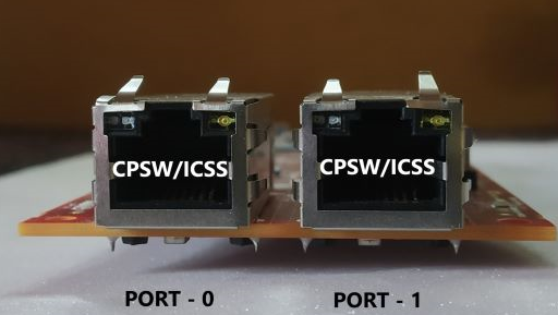
For ICSS based example
- Connect a ethernet cable to the EVM from host PC as shown below
Ethernet cable for ICSS based ethernet
AM243X-LP
- Note
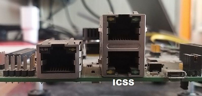
- AM243X-LP has two ethernet Ports which can be configured as ICSS ports.
For ICSS based examples
- Connect a ethernet cable to the AM243X-LP from host PC as shown below
Ethernet cable for ICSS based ethernet
Create a network between EVM and host PC
- The EVM will get an IP address using DHCP, so make sure to connect the other end of the cable to a network which has a DHCP server running.
- To get started one can create a simple local network between the EVM and the host PC by using a home broadband/wifi router as shown below. Most such routers run a DHCP server
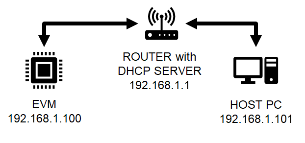
Local network between PC and EVM
- To check the router connection with host PC, recommend to disconnect all other networking conenctions on the PC, sometimes you may need to disable firewall SW, and make sure the router is able to assign a IP address to your host PC
- After we run the example on the EVM (next step), the EVM will similarly be assigned a IP address, and then host can communicate with the EVM using the assigned IP address.
Run the example
- Attention
- If you need to reload and run again, a CPU power-cycle is MUST
- Launch a CCS debug session and run the example executable, see CCS Launch, Load and Run
- You will see logs in the UART terminal as shown in the next section.
- Note the IP address seen in the log, this is what we will use to communicate with the EVM.
Sample output for ICSS example
==========================
ENET LWIP App
==========================
Enabling clocks!
PHY 3 is alive
Starting lwIP, local interface IP is dhcp-enabled
Host MAC address: 70:ff:76:1d:92:c1
[LWIPIF_LWIP] Enet has been started successfully
[LWIPIF_LWIP] NETIF INIT SUCCESS
status_callback==UP, local interface IP is 0.0.0.0
UDP server listening on port 5001
EnetPhy_bindDriver:
Icssg_handleLinkUp:
link_callback==UP
status_callback==UP, local interface IP is 192.168.0.172
5.136s : CPU load = 1.67 %
Communicate with the EVM using ethernet
- Firstly you can try to reach the EVM using ping as shown below, using a command shell on the host PC
> ping 192.168.1.100
- Next you can run
iperf tests as shown below. Below steps have been tried with a Linux Ubuntu 18.04 host PC running bash shell
- Install
iperf if not installed by doing below > sudo apt install iperf
- Invoke iperf to test TCP bi-directional RX+TX connection as shown below
> iperf -c 192.168.1.100 -i 5 -t 20 -d
Measuring the throughput using Iperf:
- Once we get the ip after running the example, we can use following iperf command on windows to get the throughput.
- iperf.exe -c 192.168.1.200 -r
Sample output for iperf command
DUT side:
==========================
ENET LWIP App
==========================
Enabling clocks!
PHY 3 is alive
Starting lwIP, local interface IP is dhcp-enabled
Host MAC address: 70:ff:76:1d:92:c1
[LWIPIF_LWIP] Enet has been started successfully
[LWIPIF_LWIP] NETIF INIT SUCCESS
status_callback==UP, local interface IP is 0.0.0.0
UDP server listening on port 5001
EnetPhy_bindDriver:
Icssg_handleLinkUp:
link_callback==UP
status_callback==UP, local interface IP is 192.168.0.172
5.136s : CPU load = 1.67 %
10.136s : CPU load = 1.31 %
15.136s : CPU load = 8.41 %
20.136s : CPU load = 50.60 %
IPERF report: type=0, remote: 192.168.0.107:47004, total bytes: 116785176, duration in ms: 10008, kbits/s: 93352
25.136s : CPU load = 50.89 %
30.136s : CPU load = 51. 6 %
IPERF report: type=1, remote: 192.168.0.107:5001, total bytes: 115837884, duration in ms: 10000, kbits/s: 92664
35.136s : CPU load = 45.28 %
PC Side:
..\iperf-2.0.9-win64>iperf.exe -c 192.168.0.172 -r
------------------------------------------------------------
Server listening on TCP port 5001
TCP window size: 208 KByte (default)
------------------------------------------------------------
------------------------------------------------------------
Client connecting to 192.168.1.200, TCP port 5001
TCP window size: 208 KByte (default)
------------------------------------------------------------
[ 4] local 192.168.1.4 port 55209 connected with 192.168.1.200 port 5001
[ ID] Interval Transfer Bandwidth
[ 4] 0.0-10.0 sec 110 MBytes 93.4 Mbits/sec
[ 4] local 192.168.1.4 port 5001 connected with 192.168.1.200 port 54911
[ 4] 0.0-10.0 sec 18.0 MBytes 92.6 Mbits/sec
Troubleshooting issues
- If you see MAC address as
00:00:00:00:00:00, likely you are using a very early Si sample which does not have MAC address "fused" in, in this case do below steps
- Open file
source\networking\enet\soc\j7x\am64x_am243x\enet_soc.c
- Uncomment below line
#define ENET_MAC_ADDR_HACK (TRUE)
- Rebuild the libraries and examples (Using SDK with Makefiles)
- If you see a valid, non-zero MAC address but IP address is
0.0.0.0 then
- Make sure you see
link_callback==UP message, if not check the ethernet cable
- Check the local network and check if the DHCP server is indeed running as expected
- When using a home broadband/wifi router, its possible to check the clients connected to the DHCP server via a web browser. Check your router user manual for more details.
See Also
Networking


 1.8.20