AM243x MCU+ SDK  08.01.00
HDSL Diagnostic

Introduction

The HDSL firmware running on ICSS-PRU provides a defined well interface to execute the HDSL protocol. The HDSL diagnostic application described here interacts with the firmware interface.

HDSL diagnostic application does below,

  • Configures pinmux, GPIO, ICSS clock to 225MHz,
  • Initializes ICSS0-PRU1, ICSS0-IEP0 and IEP1(for SYNC mode support.Timesync router is used to latch the loopback.),
  • Loads lookup table for encoding/decoding of Hiperface data
  • Loads the initialization section of PRU firmware & executes it.

Firmware is split to three sections, initialization, datalink and transport. At startup, the application displays details about encoder and status. It then presents the user with menu options, based on the option selected, application communicates with HDSL interface and the result is presented to the user.

Features Supported

  • PRU firmware source
  • External pulse synchronization
  • Safe position
  • Supports upto 100m cable
  • Communication status
  • Register interface to be compatible with SICK HDSL FPGA IP Core. (except registers that have different functionality for read and write)
  • Parameter channel communication (short message write)

SysConfig Features

Note
It is strongly recommend to use SysConfig where it is available instead of using direct SW API calls. This will help simplify the SW application and also catch common mistakes early in the development cycle.

SysConfig can be used to configure things mentioned below:

  • Selecting the ICSSG0PRUx instance.(Tested on ICSSG0-PRU1)
  • Configuring PINMUX.

Features Not Supported

In general, peripherals or features not mentioned as part of "Features Supported" section are not supported, including the below

  • Fast position, speed
  • Pipeline channel
  • Short message read
  • Safety

Important files and directory structure

Folder/Files Description
${SDK_INSTALL_PATH}/examples/motor_control/hdsl_diagnostic
hdsl_diagnostic.c Hdsl diagnostic application
hdsl_lut.c Look up tables for HDSL.
${SDK_INSTALL_PATH}/source/motor_control/position_sense/hdsl
firmware/ Folder containing HDSL PRU firmware sources.

Supported Combinations

Parameter Value
CPU + OS r5fss0-0 freertos
Toolchain ti-arm-clang
Board am243x-evm
Example folder examples/motorcontrol/hdsl_example

Steps to Run the Example

Hardware Prerequisites

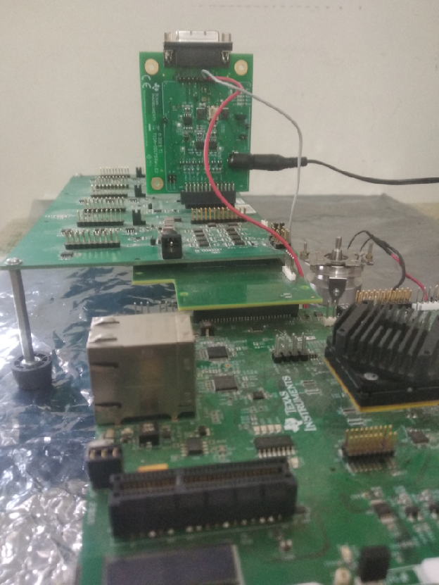
Other than the basic EVM setup mentioned in EVM Setup, below additional HW is required to run this demo

  • HDSL encoder
  • TIDA-00179 Universal Digital Interface to Absolute Position Encoders, https://www.ti.com/tool/TIDA-00179
  • TIDEP-01015 3 Axis board
  • Interface card connecting EVM and TIDEP-01015 3 Axis board

Connect the Hiperface DSL encoder to HDSL+/-(Pin number 6 and 7) signals available on header J7 or Sub-D15 connector of the "Universal Digital Interface to Absolute Position Encoders" board.

Hardware Setup

Hardware Setup

Build, load and run

  • When using CCS projects to build, import the CCS project and build it using the CCS project menu (see Using SDK with CCS Projects).
  • When using makefiles to build, note the required combination and build using make command (see Using SDK with Makefiles)
  • Launch a CCS debug session and run the executable, see CCS Launch, Load and Run
  • Refer to UART terminal for user interface menu options.

Sample Output

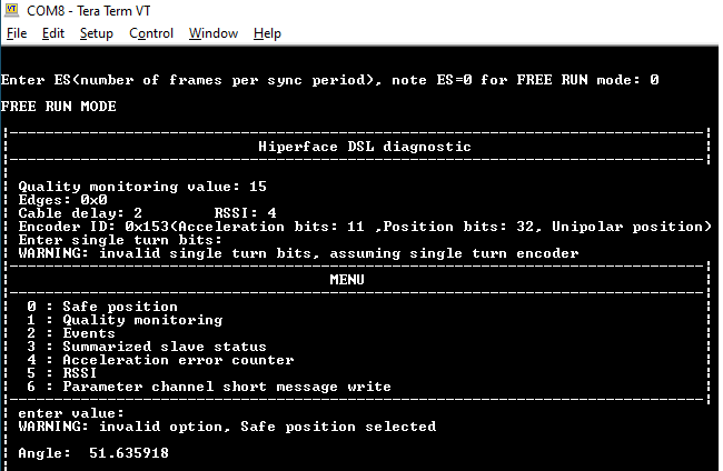
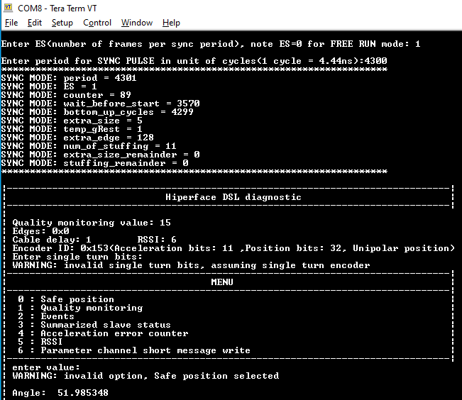
Shown below is a sample output when the application is run:

  • Freerun mode,
    HDSL Diagnostic in freerun mode
  • Sync Mode,
    HDSL Diagnostic in SYNC mode