Drivers
The TI-RTOS provides a suite of CC26xx peripheral drivers that can be added to an application. The drivers provide a mechanism for the application to interface with the CC26xx onboard peripherals and communicate with external devices. These drivers make use of DriverLib to abstract register access.
There is significant documentation relating to each TI-RTOS driver located in the BLE-Stack. Refer to the BLE-Stack release notes for the specific location. This section only provides an overview of how drivers fit into the software ecosystem. For a description of available features and driver APIs, refer to the TI-RTOS API Reference.
Adding a Driver
Some of the drivers are added to the project as source files in their respective folder under the Drivers folder in the project workspace, as shown in Figure 25.
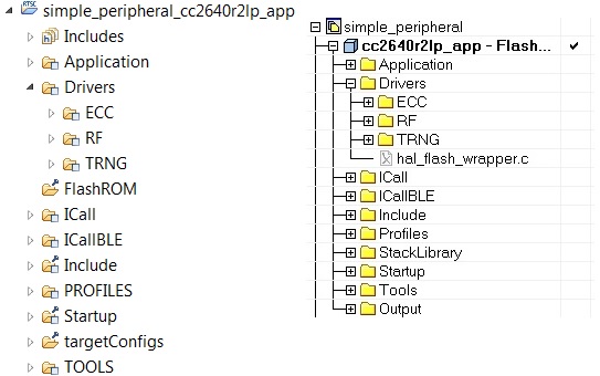
Drivers Folder
The driver source files can be found in their respective folder at $TI_RTOS_DRIVERS_BASE$\ti\drivers.
The $TI_RTOS_DRIVERS_BASE$ argument variable refers to the installation location and can be viewed in IAR Tools\ Configure Custom Argument Variables menu. For CCS, the corresponding path variables are defined in the Project Options\ Resource\Linked Resources, Path Variables tab.
The ECC and TRNG drivers, for example, are part of the BLE-Stack, not the TIRTOS, and they are located at <SDK_INSTALL_DIR>\examples\rtos\CC2640R2_LAUNCHXL\blestack\common\cc26xx\ecc and <SDK_INSTALL_DIR>\source\ti\blestack\hal\src\target\_common respectively.
To add a driver to a project, include the C and include file of the respective driver in the application file (or files) where the driver APIs are referenced.
For example, to add the PIN driver for reading or controlling an output I/O pin, add the following:
#include <ti/drivers/pin/PINCC26XX.h>
Also add the following TI-RTOS driver files to the project under the Drivers\PIN folder:
- PINCC26XX.c
- PINCC26XX.h
- PIN.h
This is described in more detail in the following sections.
Board File
The board file sets the parameters of the fixed driver configuration for a specific board configuration, such as configuring the GPIO table for the PIN driver or defining which pins are allocated to the I2C, SPI, or UART driver.
The board files for the CC2640R2 Launchpad are in the following path: <SDK_INSTALL_DIR>\examples\rtos\CC2640R2_LAUNCHXL\blestack\target\<Board_Type>
<Board_Type> is the actual device. To view the actual path to the board files, see the following:
- IAR: Tools→ Configure Custom Argument Variables
- CCS: Project Options→ Resources→ Linked Resources, Path Variables tab
In the path above, the <Board_Type> is selected based on a preprocessor symbol in the application project.
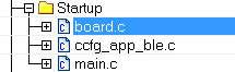
The top-level board file (board.c) then uses this symbol to include the correct board file into the project. This top-level board file can be found at <SDK_INSTALL_DIR>\examples\rtos\CC2640R2_LAUNCHXL\blestack\target\board.c, and is located under the Startup folder in the project workspace:
The board file links in another gateway board file located at <SDK_INSTALL_DIR>\examples\rtos\CC2640R2_LAUNCHXL\blestack\target\<board_type>, which finally links in the actual board file from <SDK_INSTALL_DIR>\source\ti\boards\<board_type>.
Board Level Drivers
There are also several board driver files which are a layer of abstraction on top of TI-RTOS drivers, to function for a specific board, for example Board_key.c. If desired, these files can be adapted to work for a custom board.
Creating a Custom Board File
A custom board file must be created to design a project for a custom hardware board. TI recommends starting with an existing board file and modifying it as needed. The easiest way to add a custom board file to a project is to replace the top-level board file. If flexibility is desired to switch back to an included board file, the linking scheme defined in Adding a Driver should be used.
At minimum, the board file must contain a PIN_Config structure that places all configured and unused pins in a default, safe state and defines the state when the pin is used. This structure is used to initialize the pins in main() as described in Pre-main initialization. The board schematic layout must match the pin table for the custom board file Improper pin configurations can lead to run-time exceptions:
PIN_init(BoardGpioInitTable);
See the PIN driver documentation for more information on configuring this table.
Available Drivers
This section describes each available driver and provide a basic example of adding the driver to the simple_peripheral project. For more detailed information on each driver, see the TI-RTOS API Reference.
PIN
The PIN driver allows control of the I/O pins for software-controlled general-purpose I/O (GPIO) or connections to hardware peripherals. As stated in the Board File section, the pins must first be initialized to a safe state (configured in the board file) in main(). After this initialization, any module can use the PIN driver to configure a set of pins for use. The following is an example of configuring the simple_peripheral task to use one pin as an interrupt and another as an output, to toggle when the interrupt occurs. IOID_x pin numbers map to DIO pin numbers as referenced in CC26xx Technical Reference Manual. The following table lists pins used and their mapping on the CC2640R2F LaunchPad. These are already defined in the board file.
| Signal Name | Pin ID | CC2640R2F LaunchPad Mapping |
|---|---|---|
| CC2640R2_LAUNCHXL_PIN_RLED | IOID_6 | DIO6 (Red) |
| CC2640R2_LAUNCHXL_PIN_BTN1 | IOID_13 | DIO13 (BTN_1) |
The following simple_peripheral.c code modifications are required.
Include PIN driver files:
#include <ti/drivers/pin/PINCC26xx.h>
Declare the pin configuration table and pin state and handle variables to be used by the simple_peripheral task:
Pin configuration table¶static PIN_Config SBP_configTable[] = { CC2640R2_LAUNCHXL_PIN_RLED | PIN_GPIO_OUTPUT_EN | PIN_GPIO_LOW | PIN_PUSHPULL | PIN_DRVSTR_MAX, CC2640R2_LAUNCHXL_PIN_BTN1 | PIN_INPUT_EN | PIN_PULLUP | PIN_IRQ_BOTHEDGES | PIN_HYSTERESIS, PIN_TERMINATE }; static PIN_State sbpPins; static PIN_Handle hSbpPins; static uint8_t LED_value = 0;
Declare the ISR to be performed in the hwi context:
Declare the ISR¶static void buttonHwiFxn(PIN_Handle hPin, PIN_Id pinId) { SimpleBLEPeripheral_enqueueMsg(SBP_BTN_EVT, 0, NULL); }
In SimpleBLEPeripheral_processAppMsg, add a case to handle the event from above, and define the event:
Processing of ISR event¶#define SBP_BTN_EVT static void SimpleBLEPeripheral_processAppMsg(sbcEvt_t *pMsg) { switch (pMsg->hdr.event) { case SBP_BTN_EVT: //toggle red LED if (LED_value) { PIN_setOutputValue(hSbpPins, CC2640R2_LAUNCHXL_PIN_RLED , LED_value--); } else { PIN_setOutputValue(hSbpPins, CC2640R2_LAUNCHXL_PIN_RLED, LED_value++); } break; ...
Open the pins for use and configure the interrupt in simple_peripheral_init():
Open the pins and configure the interrupt¶// Open pin structure for use hSbpPins = PIN_open(&sbpPins, SBP_configTable); // Register ISR PIN_registerIntCb(hSbpPins, buttonHwiFxn); // Configure interrupt PIN_setConfig(hSbpPins, PIN_BM_IRQ, CC2640R2_LAUNCHXL_PIN_BTN1 | PIN_IRQ_NEGEDGE); // Enable wakeup PIN_setConfig(hSbpPins, PINCC26XX_BM_WaKEUP, CC2640R2_LAUNCHXL_PIN_BTN1|PINCC26XX_WAKEUP_NEGEDGE);
Compile
Download
Run
Note
Pushing the BTN-1 button on the CC2640R2F LaunchPad toggles the red LED. No debouncing is implemented.
UART and SPI
There are many different methods of adding serial communication to a BLE project, and these are summarized in detail at the following wiki page.
Other Drivers
The other drivers included with TI-RTOS are: Crypto (AES), I2C, PDM, Power, RF, and UDMA. The stack makes use of the power, RF, and UDMA, so extra care must be taken if using these. As with the other drivers, these are well-documented, and examples are provided in the BLE-Stack.
Using 32-kHz Crystal-Less Mode
BLE-Stack 3.00.00 includes support for operating the CC2640R2F in a 32-kHz crystal-less mode for peripheral and broadcaster (beacon) configurations. By using the internal low-frequency RC oscillator (RCOSC_LF), the 32-kHz crystal can be removed from the board layout.
There are a few steps that must be taken to enable this feature. For any peripheral project, the following change is require for IAR. For CCS user, please see the Running Bluetooth Low Energy on CC2640 Without 32 kHz Crystal for the needed steps to enable RCOSC_LF in your project. You will find more detail regarding this feature in the aforementioned application note.
Include rcosc_calibration.c, rcosc_calibration.h and ccfg_app_ble_rcosc.c files which locate at <SDK_INSTALL_DIR>\examples\tos\CC2640R2_LAUNCHXL\ble\common\cc26xx\rcosc
Exclude ccfg_app_ble.c from build.
Add USE_RCOSC to Defined symbols.
Add the following code to your peripheralproject.c
RCOSC calibration include¶#ifdef USE_RCOSC #include "rcosc_calibration.h" #endif //USE_RCOSC
Add the following code to your peripheralproject_init function in peripheralproject.c
RCOSC calibration enable¶#ifdef USE_RCOSC RCOSC_enableCalibration(); #endif // USE_RCOSC
If using a custom board file, enable the RCOSC in the power policy. The board files included with the BLE-Stack:
Power driver configuration¶PowerCC26XX_Config PowerCC26XX_config = { .policyInitFxn = NULL, .policyFxn = &PowerCC26XX_standbyPolicy, .calibrateFxn = &PowerCC26XX_calibrate, .enablePolicy = TRUE, .calibrateRCOSC_LF = TRUE, .calibrateRCOSC_HF = TRUE, };
Constrain the temperature variation to be less than 1°C/sec. If the temperature is to change faster than 1°C/sec, then a short calibration interval must be used. Calibration interval can be tuned in rcosc_calibration.h
RCOSCLF calibration interval¶// 1000 ms #define RCOSC_CALIBRATION_PERIOD 1000
Note
Use of the internal RCOSC_LF requires a sleep clock accuracy (SCA) of 500 ppm.