PDM Voice
No external codec is required as the bit stream from a digital microphone can be read directly by the device, and the PDM stream can be processed in software.
The figure below shows the components required to use the TI voice solution
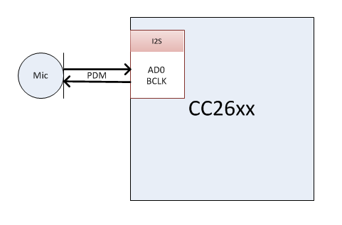
Figure 95. PDM Voice Block Diagram
Sampling
The voice solution uses the following sampling parameters:
- Sample rate: 16kHz
- Bit Depth: 16 bits
Voice quality audio is a type of audio where all information can be obtained with a low sampling rate. Whereas the typical audible spectrum is up to 20kHz, 8kHz is more than enough for voice. 16kHz sampling rate captures all information contained up to 8kHz.
The voice quality of TI’s solution has been qualified by Nuance and is sufficient for voice recognition solutions.
PDM Driver
The PDM driver is responsible for sampling the microphone data and formatting it for the user application to use.
- Collects PDM data from a PDM data microphone sampled at 1.021MHz
- Decimates the PDM input to a PCM data stream with a 16kHz sample rate and 16 bit resolution
- Encodes the PCM data using a software codec based on IMA ADPCM.
More information on the PDM driver can be found at PDM Driver Doxygen
I2S Peripheral for PDM
The PDM driver uses the I2S hardware module within the CC2640R2F to sample the PDM microphone. I2S was selected because it is a high performance peripheral capable of generating the waveforms required for PDM sampling.
More information on the I2S peripheral can be found in the CC26xx Technical Reference Manual.
The (PDM specific) I2S driver layer is implemented within the PDM Util layer. See the PDM Util Doxygen for more information.
A three wire interface is used to interface to the PDM mic. See PDM Voice Block Diagram for more info.
- GPIO: Mic power
- BCLK: Audio clock signal
- ADx: PDM input stream from mic
The settings for the I2S peripheral are initialzed in PDMCC26XX_I2S_open. The default I2S settings will work out of the box for PDM sampling. Advanced applications of the driver may require changes that are out of the scope of this document.
The GPIO pin that powers the mic is set within by the PDMCC26XX_HWAttrs, this is generally set within the board file.
IMA ADPCM Compression
If applyCompression is enabled in the PDMCC26XX_Params
then the PDM driver will use the IMA ADPCM codec implementation bundled with the
driver.
This sample implementation can be found within the TI IMA ADPCM Codec Doxygen files. Note that the TI codec includes implementation for the decode algorithms, which can be used on voice receiver devices.
PDM Driver Metadata
When using the ADPCM codec the driver will append metadata to each frame before sending it to the application. This metadata is used to ensure data integrity.
ADPCM is a differential compression format. This means that each sample depends on the previous. The metadata provides the information contained in the last sample of the previous frame. So, if a frame is lost then it will not affect the next frame. See PDMCC26XX_metaData for more information.
| Type | Description |
|---|---|
| uint8_t | Sequence Number |
| int8_t | Step Index (SI) |
| int16_t | Predicted Value (PV) |
Driver Output
The driver outputs configurable length frames.
Frame length can be modified to fit the chosen RF protocol. The driver defaults to 192 samples per frame.
At default settings, the PDM driver produces frames that are 12ms long.
(192 S) / (16 kS/s) = 12ms
Throughput Requirement
Now that we know what the driver output we can calculate the required throughput. By this we mean how many bits per second is produced by the driver. Let us use the typical configuration with 192 samples per frame. Recall that 192 samples per frame means a frame duration of 12ms.
| Data | Calculation | rate |
|---|---|---|
| Raw | (16000 S / s) * (16 bits / S) | 256kbps |
| Compressed | 256kbps / 4 | 64kbps |
| Metadata | 4 B / 12ms | 2.67kbps |
| Compressed frame with metadata | 64kbps + 2.667kbps | 66.67kpbs |