GAP Bond Manager and LE Secure Connections
The GAP Bond Manager is a configurable module that offloads most of the security mechanisms from the application. Table 10. lists the terminology.
| Term | Description |
| Pairing | The process of exchanging keys |
| Encryption | Data is encrypted after pairing, or re-encryption (a subsequent connection where keys are looked up from nonvolatile memory). |
| Authentication | The pairing process complete with MITM (Man in the Middle) protection. |
| Bonding | Storing the keys in nonvolatile memory to use for the next encryption sequence. |
| Authorization | An additional application level key exchange in addition to authentication |
| OOB | Out of Band. Keys are not exchanged over the air, but rather over some other source such as serial port or NFC. This also provides MITM protection. |
| MITM | Man in the Middle protection. This prevents an attacker from listening to the keys transferred over the air to break the encryption. |
| Just Works | Pairing method where keys are transferred over the air without MITM |
The general process that the GAPBondMgr uses is as follows:
1. The pairing process: exchange keys through the methods described in Selection of Pairing Mode.
- The encryptation process: Encrypt the link using keys Step 1.
3. The bonding process: store keys in secure flash (Simple Non Volatile memory, SNV).
- Reconnecting: Use the keys stored in SNV to encrypt the link.
Tip
Performing all of these steps is not necessary. For example, two devices may choose to pair but not bond.
Selection of Pairing Mode
Bluetooth Core Specification Version 4.2 has support for the Secure Connections feature to enable BLE pairing. For a detailed description of the algorithms used for Secure Connections, see the Security Architecture section ([Vol 1], Part A, Section 5.1) of the Bluetooth Core Specification Version 4.2. The previous pairing methods used in the Bluetooth Core Specification Versions 4.1 and 4.0 are still available, and are now defined as LE legacy pairing. The main difference is that Secure Connection uses Elliptic Curve Diffie-Hellman cryptography, while LE legacy pairing does not.
There are four types of pairing models. Each parining mode is described in detail in GAPBondMgr Examples for Different Pairing Modes.
- just works (Secure Connections or LE Legacy)
- passkey entry (Secure Connections or LE Legacy)
- numeric comparison (Secure Connections)
- out of band (Secure Connections or LE Legacy)
Which pairing model is selected, and whether or not pairing will succeed depends on the following parameters:
- Out of band (OOB) set / not set
- Man in the middle (MITM) set / not set
- In/out (IO) Capabilities
- Secure connections supported / not supported
The GAPBondMgr parameters, as they map to the table parameters below are listed here. For more information on these parameters, see BLE Stack API Reference (GAPBondMgr section).
GAPBOND_LOCAL_OOB_SC_ENABLED: Out of band (OOB) set / not setGAPBOND_MITM_PROTECTION: Man in the middle (MITM) set / not setGAPBOND_IO_CAPABILITIES: In/out (IO) CapabilitiesGAPBOND_SECURE_CONNECTION: Secure connections supported / not supportedBeyond what the Bluetooth Core Specification Version 4.2 defines, this parameter also affects whether or not pairing succeeds, as described in BLE Stack API Reference (GAPBondMgr section).
The tables below are from the Selecting Key Generation Method section ([Vol 3], Part H, Section 2.3.5.1) of the Bluetooth Core Specification Version 4.2. Use these tables to determine which parining mode is selected for any set of parameters.
If both devices support secure connections, use Figure 55. to decide upon the next step.
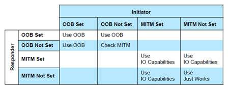
Figure 55. GAPBondMgr parameters when Secure Connections is supported by both devices.
If at least one device does not support secure connections, use Figure 56. to decide upon the next step.
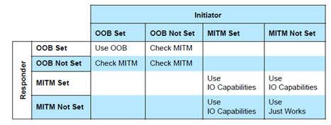
Figure 56. GAPBondMgr parameters when Secure Connections is not supported by one or both devices.
If, based on one of the previous tables, IO capabilities are to be used to determine the association model, use Figure 57.
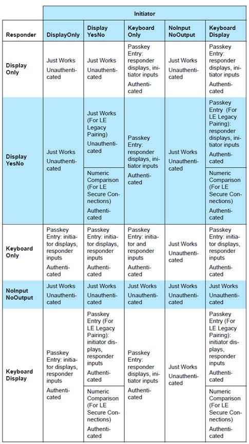
Figure 57. GAPBondMgr parameters with IO capabilities
Using GAPBondMgr
This section describes what the application must do to configure, start, and use
the GAPBondMgr. The GAPRole handles some of the GAPBondMgr functionality. The
GAPBondMgr is defined in gapbondmgr.c and gapbondmgr.h.
BLE Stack API Reference (GAPBondMgr section) describes the full API including
commands, configurable parameters, events, and callbacks.
The general steps to use the GAPBondMgr module are as follows:
1. Configure the stack to include GAPBondMgr functionality by defining the
following in build_config.opt in the stack project:
-DGAP_BOND_MGR
2. The stack must also be configured to use 1 or 2 SNV pages, by defining
OSAL_SNV=1 or OSAL_SNV=2 as a preprocessor-defined symbol in the stack
project.
3. If using Secure Connections, the PDU size must be >= 69. This can be set by
defining the following preprocessor symbol in the application project:
MAX_PDU_SIZE=69. Also, the minimum heap size that can be used with Secure
Connections is 3690. (See Dynamic Memory Allocation for heap size
management.)
4. Configure the GAPBondMgr by initializing its parameters as desired. See BLE Stack API Reference (GAPBondMgr section) for a complete list of parameters with functionality described. There are examples of this for the various pairing/bonding modes in GAPBondMgr Examples for Different Pairing Modes.
5. Register application callbacks with the GAPBondMgr, so that the application can communicate with the GAPBondMgr and be notified of events.
// Register with bond manager after starting device
GAPBondMgr_Register(&bondmanager_callbacks);
Here bondmanager_callbacks is defined as a structure containing the
GAPBondMgr Callbacks. A passcode callback function is mandatory.
// Bond Manager Callbacks
static gapBondCBs_t SimpleBLECentral_bondCB =
{
    (pfnPasscodeCB_t)SimpleBLECentral_passcodeCB, // Passcode callback
    SimpleBLECentral_pairStateCB                  // Pairing / Bonding state Callback
};
6. Once the GAPBondMgr is configured, it operates mostly autonomously from the perspective of the application. When a connection is established, the GAPBondMgr initiates pairing and bonding depending on the configuration parameters set during initialization. It also communicates with the application as needed through the defined callbacks.
A few parameters can be set and functions called asynchronously at any time from the application. See BLE Stack API Reference (GAPBondMgr section) for more information.
Most communication between the GAPBondMgr and the application at this point occurs through the callbacks which were registered in Step 5. Figure 58. is a flow diagram example of the GAPBondMgr notifying the application that pairing has been completed. The same method occurs for various other events and will be expanded upon in the following section.
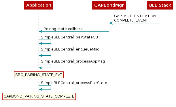
Figure 58. GapBondMgr Callback Example.
GAPBondMgr Examples for Different Pairing Modes
This section provides message diagrams for the types of security that can be implemented. These modes assume acceptable I/O capabilities are available for the security mode, and that the selection of whether or not to support Secure Connections allows for the pairing mode. See the Selection of Pairing Mode on how these parameters affect pairing. These examples only consider the pairing aspect. Bonding can be added to each type of pairing in the same manner and is shown in the next section.
Caution
The code snippets here are not complete functioning examples, and are only intended for illustration purposes.
Pairing Disabled
With pairing set to FALSE, the BLE stack automatically rejects any
attempt at pairing. Configure the GAPBondMgr as follows to disable
pairing:
uint8 pairMode = GAPBOND_PAIRING_MODE_NO_PAIRING;
GAPBondMgr_SetParameter(GAPBOND_PAIRING_MODE, sizeof(uint8_t), &pairMode);
Secure Connections
Secure Connections is enabled by default in BLE-Stack. If you don’t want to use
Secure Connections, set the GAPBOND_SECURE_CONNECTION variable to
GAPBOND_SECURE_CONNECTION_NONE during the GAPBondMgr initialization.
uint8_t gapbondSecure = GAPBOND_SECURE_CONNECTION_NONE;
GAPBondMgr_SetParameter(GAPBOND_SECURE_CONNECTION, sizeof(uint8_t), &gapbondSecure);
Just Works Pairing
Just Works pairing allows encryption without man in the middle (MITM) authentication and is thus vulnerable to MITM attacks. Just Works pairing can be LE Legacy or Secure Connections pairing. The GAPBondMgr does not need any additional input from the application for just works pairing. Configure the GAPBondMgr for Just Works pairing as follows.
uint8_t mitm = FALSE;
GAPBondMgr_SetParameter( GAPBOND_MITM_PROTECTION, sizeof (uint8_t), &mitm);
Figure 59. describes the interaction between the GAPBondMgr and
the application for Just Works pairing. As shown, the application receives a
GAPBOND_PAIRING_STATE_STARTED event once the pairing request has been sent,
and a GAPBOND_PAIRING_STATE_COMPLETE event once the pairing process has been
completed. At this time, the link is encrypted.
![@startuml
participant Application
participant GAPRole
participant Gapbondmgr as "GAPBondMgr"
participant BLEStack as "BLE Stack"
BLEStack -> GAPRole : GAP_LINK_ESTABLISHED_EVENT
GAPRole -> Gapbondmgr : GAPBondMgr_LinkEst()
Gapbondmgr -> BLEStack : GAP_Authenticate()
BLEStack -->] : Pairing req
Gapbondmgr -> Application : Pairing state callback
rnote over Application
GAPBOND_PAIRING_
STATE_STARTED
end note
BLEStack -->] : Encryption req
BLEStack <--] : Encryption rsp
BLEStack -> Gapbondmgr : GAP_AUTHENTICATION_\nCOMPLETE_EVENT
Gapbondmgr -> Application : Pairing state callback
rnote over Application
GAPBOND_PAIRING_
STATE_COMPLETE
end note
@enduml](../_images/plantuml-0b3e88b7e525b03d24326db2d2ef95b53e275aa5.png)
Figure 59. Just Works Pairing.
Passcode Entry
Passkey entry is a type of authenticated pairing that can prevent man in the middle (MITM) attacks. It can be used with either LE Legacy pairing or Secure Connections pairing. In this pairing method, one device displays a 6-digit passcode, and the other device enters the passcode. As described in Selection of Pairing Mode, the IO capabilities decide which device performs which role. The passcode callback registered with the GAPBondMgr when it was started is used to enter or display the passcode. The following is an example of initiating Passcode Entry pairing where the passcode is displayed.
- Define passcode callback
// Bond Manager Callbacks
  static gapBondCBs_t SimpleBLECentral_bondCB =
  {
      (pfnPasscodeCB_t)SimpleBLECentral_passcodeCB, // Passcode callback
      SimpleBLECentral_pairStateCB                  // Pairing / Bonding state Callback
  };

  /*********************************************************************
  * @fn      SimpleBLECentral_passcodeCB
  *
  * @brief   Passcode callback.
  *
  * @return  none
  */
  static void SimpleBLECentral_passcodeCB(uint8_t *deviceAddr, uint16_t connHandle, uint8_t uiInputs, uint8_t uiOutputs)
  {
      uint8_t *pData;

      // Allocate space for the passcode event.
      if ((pData = ICall_malloc(sizeof(uiOutputs))))
      {
          *pData = uiOutputs;

          // Enqueue the event.
          SimpleBLECentral_enqueueMsg(SBC_PASSCODE_NEEDED_EVT, 0, pData);
      }
  }
- Configure GAPBondMgr
uint8_t pairMode = GAPBOND_PAIRING_MODE_INITIATE;
uint8_t mitm = TRUE;
GAPBondMgr_SetParameter(GAPBOND_PAIRING_MODE, sizeof(uint8_t), &uint8_t pairMode = GAPBOND_PAIRING_MODE_INITIATE;
GAPBondMgr_SetParameter(GAPBOND_PAIRING_MODE, sizeof(uint8_t), &mitm);
- Process passcode callback and send the response to the stack.
//! BLE Default Passcode
#define B_APP_DEFAULT_PASSCODE                    123456

static void SimpleBLECentral_processPasscode(uint16_t connectionHandle, uint8_t uiOutputs)
{
  // This app uses a default passcode. A real-life scenario would handle all
  // pairing scenarios and likely generate this randomly.
  uint32_t passcode = B_APP_DEFAULT_PASSCODE;

  // Display passcode to user
  if (uiOutputs != 0)
  {
      Display_print1(dispHandle, 4, 0, "Passcode: %d", passcode);
  }

  // Send passcode response
  GAPBondMgr_PasscodeRsp(connectionHandle, SUCCESS, passcode);
}
Depending on the uiInputs and uiOutputs returned from the GAPBondMgr,
the passcode must either be displayed or entered. The passcode is
then sent to the GAPBondMgr using GAPBondMgr_PasscodeRsp(), so that
pairing can continue. ThIn this case, the password is statically set to 123456.
In a real product, the password will likely be randomly generated, and the
device must expose a way for the user to enter the passcode, then send it to the
GAPBondMgr using GAPBondMgr_PasscodeRsp(). An example interaction
between the GAPBondMgr and the application is shown in
Figure 60..
![@startuml
participant Application
participant GAPRole
participant Gapbondmgr as "GAPBondMgr"
participant BLEStack as "BLE Stack"
BLEStack -> GAPRole : GAP_LINK_ESTABLISHED_EVENT
GAPRole -> Gapbondmgr : GAPBondMgr_LinkEst()
Gapbondmgr -> BLEStack : GAP_Authenticate()
BLEStack -->] : Pairing req
Gapbondmgr -> Application : Pairing state callback
rnote over Application
GAPBOND_PAIRING_
STATE_STARTED
end note
BLEStack -> Gapbondmgr : GAP_PASSKEY_NEEDED_\nEVENT
Gapbondmgr -> Application : Passcode callback
[--> Application : Enter or display\npasscode
Application -> Gapbondmgr : GAPBondMgr_PasscodeRsp()
Gapbondmgr -> BLEStack : GAP_PasscodeUpdate()
BLEStack -->] : Encryption req
BLEStack <--] : Encryption rsp
BLEStack -> Gapbondmgr : GAP_AUTHENTICATION_\nCOMPLETE_EVENT
Gapbondmgr -> Application : Pairing state callback
rnote over Application
GAPBOND_PAIRING_
STATE_COMPLETE
end note
@enduml](../_images/plantuml-7e804e772b265336f6100e616249b21c914c3b4d.png)
Figure 60. Interaction Between the GAPBondMgr and the Application when exchanging a passcode.
Numeric Comparison
Numeric comparison is a type of authenticated pairing that protects from MITM attacks. It is only possible as a Secure Connections pairing; not LE legacy. For numeric comparison pairing, both devices display a 6-digit code. Each device must then indicate, through a button press or some other yes-no input, whether the codes match. The passcode callback registered with the GAPBondMgr when it was started is used to display the 6-digit code. The following is an example of initiating Numeric Comparison pairing where the passcode is displayed. The IO capabilities must be set appropriately to select numeric comparison (that is, Display/Yes-No on both sides).
- Define passcode callback to display code.
1 2 3 4 5 6 7 8 9 10 11 12 13 14 15 16 17 18 19 20 | // Bond Manager Callbacks
static gapBondCBs_t SimpleBLECentral_bondCB =
{
(pfnPasscodeCB_t)SimpleBLECentral_passcodeCB, //Passcode callback
SimpleBLECentral_pairStateCB //Pairing state callback
};
static void SimpleBLECentral_passcodeCB (uint8_t *deviceAddr, uint16_t connHandle, uint8_t uiInputs, uint8_t uiOutputs, uint32_t numComparison)
{
gapPasskeyNeededEvent_t *pData;
// Allocate space for the passcode event.
if ((pData = ICall_malloc(sizeof(gapPasskeyNeededEvent_t))))
{
memcpy(pData->deviceAddr, deviceAddr, B_ADDR_LEN);
pData->connectionHandle = connHandle;
pData->numComparison = numComparison;
// Enqueue the event.
SimpleBLECentral_enqueueMsg(SEC_PASSCODE_NEEDED_EVT, 0, (uint8_t *) pData);
|
- Configure GAPBondMgr
1 2 3 4 5 6 7 8 9 | uint8_t pairMode = GAPBOND_PAIRING_MODE_INITIATE;
uint8_t scMode = GAPBOND_SECURE_CONNECTION_ONLY;
uint8_t mitm = TRUE;
uint8_t ioCap = GAPBOND_IO_CAP_DISPLAY_YES_NO;
GAPBondMgr_SetParameter(GAPBOND_IO_CAPABILITIES, sizeof(uint8_t), &ioCap);
GAPBondMgr_SetParameter(GAPBOND_PAIRING_MODE, sizeof(uint8_t), &pairMode);
GAPBondMgr_SetParameter(GAPBOND_MITM_PROTECTION, sizeof(uint8_t), &mitm);
GAPBondMgr_SetParameter(GAPBOND_SECURE_CONNECTION, sizeof(uint8_t), &scMode);
|
- Process passcode callback and display code.
1 2 3 4 5 6 7 8 9 10 | static void SimpleBLECentral_processPasscode (uint16_t connectionHandle, gapPasskeyNeededEvent_t *pData)
{
if (pData->numComparison) //numeric comparison
{
//Display passcode
DISPLAY_WRITE_STRING_VALUE("Num Cmp: %d", pData->numComparison, LCD_PAGE4);
}
}
|
- Accept Yes-No input from user and send response to GAPBondMgr.
1 2 3 4 5 6 | if (keys & KEY_RIGHT)
{
GAPBondMgr_PasscodeRsp(connHandle, SUCCESS, TRUE);
DISPLAY_WRITE_STRING("Codes Match!", LCD_PAGE5);
return;
}
|
In this case, the third parameter of GAPBondMgr_PasscodeRsp, which usually accepts a passcode, is overloaded to send TRUE to the stack to indicate that the codes match and to continue with pairing. The process of numeric comparison is illustrated in Figure 61..
![@startuml
participant Application
participant GAPRole
participant Gapbondmgr as "GAPBondMgr"
participant BLEStack as "BLE Stack"
BLEStack -> GAPRole : GAP_LINK_ESTABLISHED_EVENT
GAPRole -> Gapbondmgr : GAPBondMgr_LinkEst()
Gapbondmgr -> BLEStack : GAP_Authenticate
BLEStack -->] : Pairing req
Gapbondmgr -> Application : Pairing state callback
rnote over Application
GAPBOND_PAIRING_
STATE_STARTED
end note
BLEStack -> Gapbondmgr : GAP_PASSKEY_\nNEEDED_EVENT
Gapbondmgr -> Application : Passcode callback
[<-- Application : Display code
[--> Application : Codes match
Application -> Gapbondmgr : GAPBondMgr_PasscodeRsp()
Gapbondmgr -> BLEStack : GAP_PasscodeUpdate()
BLEStack -->] : Encryption req
BLEStack <--] : Encryption rsp
BLEStack -> Gapbondmgr : GAP_AUTHENTICATION_\nCOMPLETE_EVENT
Gapbondmgr -> Application : Pairing state callback
rnote over Application
GAPBOND_PAIRING_
STATE_COMPLETE
end note
@enduml](../_images/plantuml-3ba35e48e570b61dda64b15eb57ad6e4c67b624c.png)
Figure 61. Numeric Comparison.
GAPBondMgr Example With Bonding Enabled
Bonding can enabled or disabled for any type of pairing through the
GAPBOND_BONDING_ENABLED parameter, and occurs after the pairing
process is complete. To enable bonding, configure the GAPBondMgr as
follows:
uint8_t bonding = TRUE;
GAPBondMgr_SetParameter(GAPBOND_BONDING_ENABLED, sizeof(uint8_t), &bonding);
With bonding enabled, the GAPBondMgr stores the long-term key
transferred during the pairing process to SNV. See GAPBondMgr and SNV for more information. After this is completed, the application is notified
through the GAPBOND_PAIRING_STATE_COMPLETE event. GAPBOND_PAIRING_STATE_BOND_SAVED is only passed to the application pair
state callback when initially connecting, pairing, and bonding. For
future connections to a bonded device, the security keys are loaded from
flash, thus skipping the pairing process. In this case, only
GAPBOND_PAIRING_STATE_BONDED is passed to the application pair state callback. This is illustrated in Figure 62.
![@startuml
participant Application
participant GAPRole
participant Gapbondmgr as "GAPBondMgr"
participant BLEStack as "BLE Stack"
BLEStack -> GAPRole : GAP_LINK_ESTABLISHED_EVENT
GAPRole -> Gapbondmgr : GAPBondMgr_LinkEst()
Gapbondmgr -> BLEStack : GAP_Authenticate
BLEStack -->] : Pairing req
Gapbondmgr -> Application : Pairing state callback
rnote over Application
GAPBOND_PAIRING_
STATE_STARTED
end note
== This section will vary depending on the pairing type.\nSee above examples for more information. ==
BLEStack -->] : Encryption req
BLEStack <--] : Encryption rsp
BLEStack -> Gapbondmgr : GAP_AUTHENTICATION_\nCOMPLETE_EVENT
rnote over Gapbondmgr
Save bond info in SNV
end note
Gapbondmgr -> Application : Pairing state callback
rnote over Application
GAPBOND_PAIRING_
STATE_COMPLETE
end note
rnote over Application
GAPBOND_PAIRING_
STATE_BOND_SAVED
end note
== Eventually the connection may be terminated and re-established. ==
BLEStack -> GAPRole : GAP_LINK_ESTABLISHED_EVENT
GAPRole -> Gapbondmgr : GAPBondMgr_LinkEst()
rnote over Gapbondmgr
Read bond info from SNV.
end note
Gapbondmgr -> BLEStack : GAP_Bond()
BLEStack -->] : Encryption req
BLEStack <--] : Encryption rsp
BLEStack -> Gapbondmgr : GAP_BOND_COMPLETE_\nEVENT
Gapbondmgr -> Application : Pairing state callback
rnote over Application
GAPBOND_PAIRING_
STATE_BONDED
end note
@enduml](../_images/plantuml-16e27601da92bb5510ccdb4ef7047579775f758c.png)
Figure 62. GAPBondMgr Example With Bonding Enabled.
GAPBondMgr and SNV
This section describes how the GAPBondMgr uses the SNV flash area
for storing bonding information. For more information on SNV itself,
see Flash. The amount of bonds that can be stored
is set by the GAP_BONDINGS_MAX definition, which is set to 10 by default in
gapbondmgr.h. The functionality of the GAPBondMgr when there are no
more available bonds varies based on whether the “least recently
used” scheme is enabled. See BLE Stack API Reference (GAPBondMgr section) for
more information
on the GAPBOND_LRU_BOND_REPLACEMENT parameter. If this parameter is set
to false, it is not possible to add any more bonds without manually
deleting a bond. If the parameter is set to true, the least recently
used bond is deleted to make room for the new bond.
The following components comprise one bonding entry:
- Bond Record: this consists of the peer’s address, address type, privacy reconnection address, and state flags. This comprises 14 bytes and is defined as such:
typedef struct
{
  uint8   publicAddr[B_ADDR_LEN];     // Peer's address
  uint8   publicAddrType;             // Peer's address type
  uint8   reconnectAddr[B_ADDR_LEN];  // Privacy Reconnection Address
  uint8   stateFlags;                 // State flags: @ref GAP_BONDED_STATE_FLAGS
} gapBondRec_t;
- Client Characteristic Configurations (CCC): the amount of CCCs stored
in each entry are set by the
GAP_CHAR_CFG_MAXdefine. This is set to 4 by default. Each CCC is comprised of 4-bytes and is defined as follows:
typedef struct
{
  uint16 attrHandle;  // attribute handle
  uint8  value;       // attribute value for this device
} gapBondCharCfg_t;
- Local Long Term Key (LTK) info: this stores the local device’s encryption information. This comprises 28 bytes and is composed as such:
typedef struct
{
  uint8   LTK[KEYLEN];              // Long Term Key (LTK)
  uint16  div;  //lint -e754        // LTK eDiv
  uint8   rand[B_RANDOM_NUM_SIZE];  // LTK random number
  uint8   keySize;                  // LTK key size
} gapBondLTK_t;
- Connected Device Long Term Key Info: this stores the connected device’s encryption information. This is also a gapBondLTK_t and comprises 28 bytes.
- Connected Device Identity Resolving Key (IRK): this stores the IRK generated during pairing. This is a 16-byte array.
- Connected Device Sign Resolving Key (SRK): this stores the SRK generated during pairing. This is a 16-byte array.
- Connected Device Sign counter: this stores the sign counter generated during pairing. This is a 4-byte word.
LE Privacy 1.2
Summary
BLE-Stack 3.01.01.00 and newer support the privacy feature that reduces the ability to track an LE device over a period of time, by changing the Bluetooth device address on a frequent basis. LE Privacy 1.2 extends privacy to the controller by allowing the controller to both resolve peer and generate local resolvable private addresses (RPAs). It is used during connection mode and connection procedures. In BLE-Stack 3.01.01.00, Privacy 1.2 is always enabled. Table 11. lists the definition of terms related to the privacy feature.
| Term | Definition |
|---|---|
| Resolvable address | A resolvable address is one that can potentially be resolved. Resolvable address Specifically, it is a device address that is a random resolvable private address (RPA). |
| Resolving list (RL) | One or more entries of local/peer IRK pairs associated with an identity address (public or random static). |
| Device address | A 48-bit value used to identify a device. A device address can be public or random. A device may use at least one, and can use both. |
| Identity (ID) address | An RPA is resolved with an identity resolving key (IRK) and is associated with a public address or a random static address, known as the identity (ID) address. |
| Non-resolvable address | A non-resolvable address is one that can never be resolved. Specifically, it is a device address that is a public address, a random static address, or a non-resolvable private address. |
Theory of Operation
For a device using the privacy feature to reconnect to known devices, the device address, referred to as the private address, must be resolvable by the other device. The private address is generated using the device’s resolving identity key (IRK) exchanged during the bonding procedure.
With LE Privacy 1.2, the host is able to populate a resolving list in the controller. The resolving list consists of a set of records, where each record contains a pair of IRKs, one for local and one for peer, as well as the identity address of the peer device. A identity address of the peer device should be the public or static address of that device, which is obtained during phase 3 of pairing. The controller, which now contains all of the IRKs for previously bonded devices, is able to resolve private addresses into identity addresses of peers. These addresses are then able to be passed to the controller white list for further action, as shown in Figure 63.
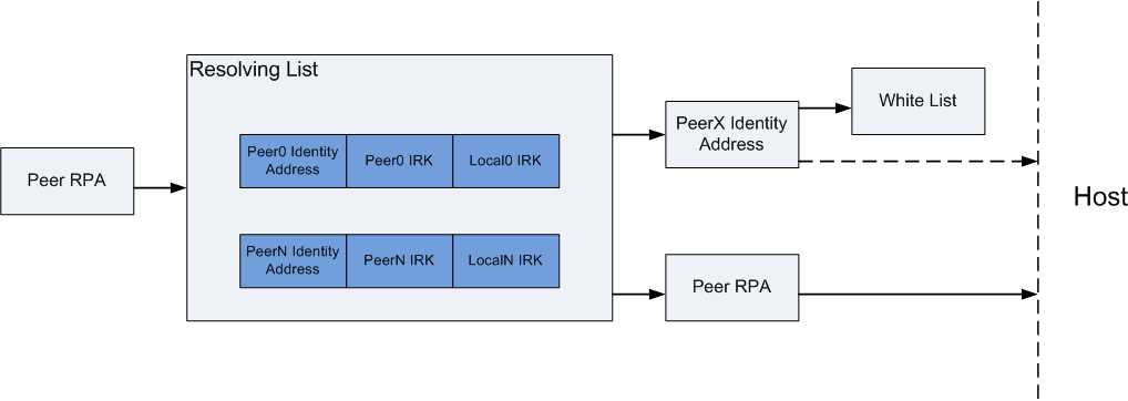
Figure 63. Resolving List.
If the controller is unable to resolve the peer RPAs, or the white list takes no actions for the incoming address, the address is still passed to the host. If the local device or peer device wishes, it can initiate a bonding sequence to exchange IRKs as well as device identity addresses. If these are exchanged, the host can use those parameters to update the controller’s resolving list, and even update the white list, so that the controller can automatically form a connection with the peer during a future connection attempt.
New HCI Commands
The following new HCI commands are now supported in the controller:
- LE Add Device to Resolving List Command
- LE Remove Device to Resolving List Command
- LE Clear Resolving List Command
- LE Read Resolving List Size Command
- LE Read Peer Resolvable Address Command
- LE Read Local Resolvable Address Command
- LE Set Address Resolution Enable Command
- LE Set Random Private Address Timeout Command
For additional details, please see Bluetooth Core_v4.2 specification (Vol 2, Part E, Section 7.8 for the commands, and Section 7.7 for the event).
Privacy and White List
Enabling Auto Sync of White List
The stack can automatically add devices to the white list after bonding. Use the following code to enable this syncing of the white list.
1 2 | uint8_t autoSyncWhiteList = TRUE;
GAPBondMgr_SetParameter(GAPBOND_AUTO_SYNC_WL, sizeof(uint8_t), &autoSyncWhiteList);
|
Using Resolvable Private Addresses
The device also can be configured to use a random address. Use GAP_ConfigDeviceAddr()
to use random address. This API must be called after the GAP layer is started but cannot
be called during any BLE activity. In the function gapRole_processGAPMsg() add the
code below after gapRole_state = GAPROLE_STARTED:
//set address type to resolvable private address
status = GAP_ConfigDeviceAddr(ADDRMODE_PRIVATE_RESOLVE, NULL);

if (status != SUCCESS)
{
    System_abort("Error!");
}
It can be verified with a sniffer that the address changes when advertising. The default timeout value between private (resolvable) address changes is 15 minutes. This can be modified by GAP_SetParamValue() after calling GAP_ConfigDeviceAddr():
//Set timeout value to 5 minute
GAP_SetParamValue( TGAP_PRIVATE_ADDR_INT , 5);

// Update the advertising data
//...
Testing Privacy with White List
The following steps can be made to test the privacy with white list feature:
- Connect a iOS device to the CC2640R2F both supporting Privacy 1.2.
- Pair with the device with the default passcode: 000000.
- The iOS devices should be automatically added to the white list.
- Disconnect and wait for the iOS device address to change.
- Reconnect to the CC2640R2F.