Generic Access Profile (GAP)
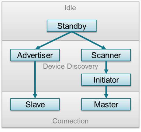
The GAP layer of the Bluetooth low energy protocol stack is responsible for connection functionality. This layer handles the access modes and procedures of the device including device discovery, link establishment, link termination, initiation of security features, and device configuration. See GAP State Diagram. for more details.

Figure 34. GAP State Diagram.
Based on the role for which the device is configured, GAP State Diagram. shows the states of the device. The following describes these states.
- Standby: The device is in the initial idle state upon reset.
- Advertiser: The device is advertising with specific data letting any initiating devices know that it is a connectible device (this advertisement contains the device address and can contain some additional data such as the device name).
- Scanner: When receiving the advertisement, the scanning device sends a scan request to the advertiser. The advertiser responds with a scan response. This process is called device discovery. The scanning device is aware of the advertising device and can initiate a connection with it.
- Initiator: When initiating, the initiator must specify a peer device address to which to connect. If an advertisement is received matching that address of the peer device, the initiating device then sends out a request to establish a connection (link) with the advertising device with the connection parameters described in Connection Parameters.
- Slave/Master: When a connection is formed, the device functions as a slave if the advertiser and a master if the initiator.
Connection Parameters
This section describes the connection parameters which are sent by the initiating device with the connection request and can be modified by either device when the connection is established. These parameters are as follows:
- Connection Interval - In Bluetooth low energy connections, a
frequency-hopping scheme is used. The two devices each send and
receive data from one another only on a specific channel at a
specific time. These devices meet a specific amount of time later
at a new channel (the link layer of the Bluetooth low energy
protocol stack handles the channel switching). This meeting is
where the two devices send and receive data is known as a
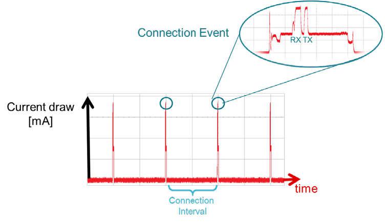
connection event. If there is no application data to be sent or received, the two devices exchange link layer data to maintain the connection. The connection interval is the amount of time between two connection events in units of 1.25 ms. The connection interval can range from a minimum value of 6 (7.5 ms) to a maximum of 3200 (4.0 s). See Connection Event and Interval for more details.

Figure 35. Connection Event and Interval
Different applications may require different connection intervals. As described in Connection Parameter Considerations, these requirements affect the power consumption of the device. For more detailed information on power consumption, see Measuring Bluetooth Smart Power Consumption Application Report (SWRA478).
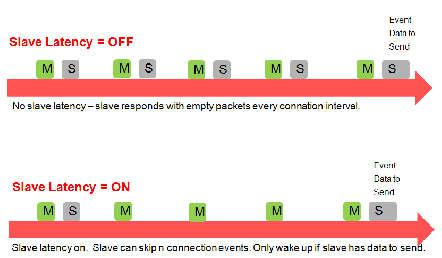
- Slave Latency - This parameter gives the slave (peripheral) device the option of skipping a number of connection events. This ability gives the peripheral device some flexibility. If the peripheral does not have any data to send, it can skip connection events, stay asleep, and save power. The peripheral device selects whether to wake or not on a per connection event basis. The peripheral can skip connection events but must not skip more than allowed by the slave latency parameter or the connection fails. See Slave Latency for more details.

Figure 36. Slave Latency
- Supervision Time-out - This time-out is the maximum amount of time between two successful connection events. If this time passes without a successful connection event, the device terminates the connection and returns to an unconnected state. This parameter value is represented in units of 10 ms. The supervision time-out value can range from a minimum of 10 (100 ms) to 3200 (32.0 s). The time-out must be larger than the effective connection interval (see Effective Connection Interval for more details).
Effective Connection Interval
The effective connection interval is equal to the amount of time between two connection events, assuming that the slave skips the maximum number of possible events if slave latency is allowed (the effective connection interval is equal to the actual connection interval if slave latency is set to 0).
The slave latency value represents the maximum number of events that can be skipped. This number can range from a minimum value of 0 (meaning that no connection events can be skipped) to a maximum of 499. The maximum value must not make the effective connection interval (see the following formula) greater than 16 s. The interval can be calculated using the following formula:
Effective Connection Interval = (Connection Interval) * (1 + [Slave
Latency])
Consider the following example:
- Connection Interval: 80 (100 ms)
- Slave Latency: 4
- Effective Connection Interval: (100 ms) * (1 + 4) = 500 ms
When no data is being sent from the slave to the master, the slave transmits during a connection event once every 500 ms.
Connection Parameter Considerations
In many applications, the slave skips the maximum number of connection events. Consider the effective connection interval when selecting or requesting connection parameters. Selecting the correct group of connection parameters plays an important role in power optimization of the Bluetooth low energy device. The following list gives a general summary of the trade-offs in connection parameter settings.
Reducing the connection interval does as follows:
- Increases the power consumption for both devices
- Increases the throughput in both directions
- Reduces the time for sending data in either direction
Increasing the connection interval does as follows:
- Reduces the power consumption for both devices
- Reduces the throughput in both directions
- Increases the time for sending data in either direction
Reducing the slave latency (or setting it to zero) does as follows:
- Increases the power consumption for the peripheral device
- Reduces the time for the peripheral device to receive the data sent from a central device
Increasing the slave latency does as follows:
- Reduces power consumption for the peripheral during periods when the peripheral has no data to send to the central device
- Increases the time for the peripheral device to receive the data sent from the central device
Connection Parameter Limitations with Multiple Connections
There are additional constraints that exist when connected to multiple devices or performing multiple GAP roles simultaneously. See the multi_role example in BLE5-Stack 1.00.01.05.
Connection Parameter Update
In some cases, the central device requests a connection with a
peripheral device containing connection parameters that are
unfavorable to the peripheral device. In other cases, a peripheral
device might have the desire to change parameters in the middle of a
connection, based on the peripheral application. The peripheral
device can request the central device to change the connection
settings by sending a Connection Parameter Update Request. For
Bluetooth 4.1 and 4.2-capable devices, this request is handled directly by
the Link Layer. For Bluetooth 4.0 devices, the L2CAP layer of the
protocol stack handles the request. The Bluetooth low energy stack
automatically selects the update method.
This request contains four parameters: minimum connection interval, maximum connection interval, slave latency, and time-out. These values represent the parameters that the peripheral device needs for the connection (the connection interval is given as a range). When the central device receives this request, it can accept or reject the new parameters.
Sending a Connection Parameter Update Request is optional and is not
required for the central device to accept or apply the requested
parameters. Some applications try to establish a connection at a
faster connection interval to allow for a faster service discovery
and initial setup. These applications later request a longer
(slower) connection interval to allow for optimal power usage.
Depending on the GAPRole, connection parameter updates can be sent
asynchronously with the GAPRole_SendUpdateParam() or
GAPCentralRole_UpdateLink() command. The peripheral GAPRole can be
configured to automatically send a parameter update a certain amount of time
after establishing a connection. For example, the simple_peripheral
application uses the following preprocessor-defined symbols:
Six seconds after a connection is established, the GAP layer
automatically sends a connection parameter update. This action
can be disabled by changing DEFAULT_ENABLE_UPDATE_REQUEST to e.g.
GAPROLE_LINK_PARAM_UPDATE_WAIT_REMOTE_PARAMS. See Peripheral Role
for an explanation of how the parameters are configured.
Connection Termination
Either the master or the slave can terminate a connection for any reason. One side initiates termination and the other side must respond before both devices exit the connected state.
GAP Abstraction
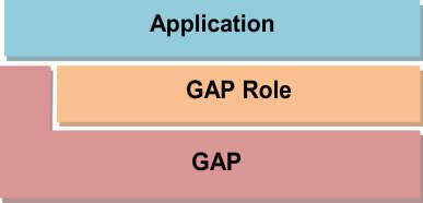
The application and profiles can directly call GAP API functions to perform Bluetooth low energy-related functions such as advertising or connecting. Most of the GAP functionality is handled by the GAPRole Task. GAP Abstraction shows this abstraction hierarchy.

Figure 37. GAP Abstraction
Access the GAP layer through direct calls or through the GAPRole task as described in GAPRole Task. Use the GAPRole task rather than direct calls when possible. Configuring the GAP Layer describes the functions and parameters that are not handled or configured through the GAPRole task and must be modified directly through the GAP layer.
Configuring the GAP Layer
The GAP layer functionality is mostly defined in library code. The
function headers can be found in gap.h in the protocol stack
project. Most of these functions are used by the GAPRole and do not
need to be called directly. For reference, see BLE Stack API Reference
(GATTServApp section).
Several parameters exist which may be desirable to modify before starting the
GAPRole. These parameters can be set or get through the
GAP_SetParamValue() and GAP_GetParamValue() functions and
include advertising and scanning intervals, windows, and so forth (see the API
for more information). The following is the configuration of the GAP layer in
simple_peripheral_init():
1 2 3 4 5 6 7 8 9 | // Set advertising interval
{
uint16_t advInt = DEFAULT_ADVERTISING_INTERVAL;
GAP_SetParamValue(TGAP_LIM_DISC_ADV_INT_MIN, advInt);
GAP_SetParamValue(TGAP_LIM_DISC_ADV_INT_MAX, advInt);
GAP_SetParamValue(TGAP_GEN_DISC_ADV_INT_MIN, advInt);
GAP_SetParamValue(TGAP_GEN_DISC_ADV_INT_MAX, advInt);
}
|
The above code sets the advertising interval for limited and general
advertising modes. By default, the peripheral advertises in general
discoverable mode. To use limited discoverable mode, the
corresponding fields inside the advertising data packet should be
changed by defining DEFAULT_DISCOVERABLE_MODE to
GAP_ADTYPE_FLAGS_LIMITED.