Introduction
==================================
This introduction lab introduces the concepts of Tasks, Hwi, Semaphores as well as the PIN driver step by step using TI-RTOS on the CC26xx.
Prerequisites
==================================
Software
---------
* CCS 6.1 or later
* TI-RTOS 2.20.01.08 or later
* Note that the version of TI-RTOS bundled with the TI BLE SDK will work.
Hardware
---------
* 1x CC2650EM Evaluation Module
* 1x SmartRF06 Evaluation Board
Or,
* 1x CC2650ST SensorTag
* 1x CC-DEVPACK-DEBUG
Or,
* 1x CC2650 Launchpad
Getting started
==================================
Making sure it works
---------------------------------
Start by making sure the kit is properly assembled, either with the EM placed on the SmartRF06 board and turned ON, or the Debug Devpack attached to the SensorTag. Ensure that the board is connected to the PC.
Open Code Composer Studio and import the project.
* Open the Resource Explorer by going to View → Resource Explorer (Examples)
* Open up SimpleLink Academy → TI-RTOS → Projects
* Select `Lab 1` for the platform you are using.
* Press the import button on the right side
To test that the software and hardware pre-requisites are fulfilled we are going to try to build and debug the project before going to the first task.
* Our first mission is to build the imported project. Select the project in Project Explorer and choose Project → Build All from the menu.
* When the project is built, we are going to make sure that the hardware and debugger work. To start debugging, press Run → Debug, or press F11.
* When the download is finished, press F8 or the green play button to run.
* After a few seconds you should see LED1 toggling on and off every second.
If you see LED1 blink then everything works and you may continue with the lab.
[[y On Building
Note that the first time you build the project the whole TI-RTOS kernel will also be built. This may take several minutes, but is only done the first time. Subsequent builds will re-use the compiled kernel unless a configuration change is done.
]]
Orienting ourselves in the code
---------------------------------
The Lab 1 example comes preconfigured with one TI-RTOS `Task` already constructed in `main()`. This task is set up to use the `workTaskFunc` function as the task function, which in turn uses the PIN Driver to toggle a led.
The task is created using the `Task_construct` in the main function. The main function also initializes the hardware.
In the `main()` function, after `BIOS_start()` is called, the main function will not progress further, but instead give control to the TI-RTOS scheduler which will call the `Task functions` of the tasks that are constructed. For example `workTaskFunc`. Normally, task functions will enter an infinite loop and never return, letting TI-RTOS switch to higher priority tasks or temporarliy suspend the current task.
Task 0 - Basic RTOS debugging
==================================
First we are going to take a look at some of the built in features of CCS which can aid in the development of firmware running on TI-RTOS, and also give a better understanding of the multitasking.
RTOS Object View
---------------------------------
The RTOS Object View, or ROV for short can be used to get a snapshot of the whole RTOS. By default the information is only updated via JTAG when the target is halted.
First we are going to halt the code as we are toggling the led.
* Put a breakpoint in the workTaskFunc on the `doWork` line
* Do this by double clicking on the area on the left of the line number.
* Run so you hit that breakpoint.
Next open the ROV by going to Tools → RTOS Object View (ROV). This will open up a new tab where you can see a lot of information about RTOS objects when you have Instrumentation enabled.
What we are looking for is the Task module's Details tab.
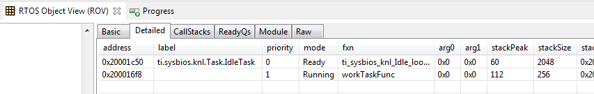
This view shows which task is currently running on the system, what tasks are blocked as well as what tasks are ready to run.
We can see that the workTaskFunc is currently running and we can also see that the stack usage for the task has peaked at 112 of 256 bytes so far, so no risk of stack overflow yet!
Execution graph
---------------------------------
While the ROV is handy to get a snapshot view over the current state of the system it is not possible to get any information about the state of the system over time. For this we use the Execution graph.
First, before we start up the execution graph, make sure that the application has been running for a short while. After the LED has had time to blink a few times, press Halt/Suspend/Pause button to pause the execution of the program.
Next, open the Execution Analysis menu by going to Tools → RTOS Analyzer → Execution Analysis.
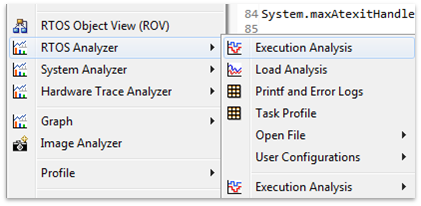
Select only the `Execution Graph` in the next window, leave everything else as it was and press Start.
In the new Execution Graph tab, expand `Cortex_M3_0.*OS` to see that `Task.workTaskFunc` has been executing! In fact, it's the only task executing. The `Idle` task has not gotten any time at all during the execution of the program. This is usually a sign that one task is hogging all system resources and is in most cases because of a bug.
[[b How does the logging work?
The TI-RTOS module LoggingSetup, which is part of the Universal Instrumentation Architecture (UIA), sets the UIA module LoggerStopMode up as an interface for the XDC Runtime Log module, which again has hooks into the Task, Hwi and Swi modules.
The TI-RTOS configuration script parsing acts as an extra precompile step which can add, remove and configure RTSC (Real-Time Software Components) modules by outputting .c and .h files used for later compilation and linking.
]]
Task 1 - Sleeping well
==================================
After looking at the Execution Graph, we can see that we have a problem with one of our tasks hogging all CPU resources. Let's take a look at our workTaskFunc.
```c
void doWork(void)
{
PIN_setOutputValue(pinHandle, Board_LED1, 1);
FakeBlockingWork(); /* Pretend to do something useful but time-consuming */
PIN_setOutputValue(pinHandle, Board_LED1, 0);
}
Void workTaskFunc(UArg arg0, UArg arg1)
{
while (1) {
/* Do work */
doWork();
/* Sleep */
CPUdelay(24e6);
}
}
``` Work, sleep, work.
The only thing the task does is execute the doWork function and then goes back to 'sleep', except it never does go to sleep. The `CPUdelay` function is simply a function which burns CPU cycles in a loop. This is not the correct way to pass time in the RTOS.
One of the easiest ways to pass time in a task is to call `Task_sleep(numTicks [tick])`. `Task_sleep` will simply make the current task sleep for as many system ticks as is specified in the argument. The current tick rate of the system is needed in order to know how long you will sleep. This is a constant value available via the `Clock_tickPeriod` variable. The value is the amount of `microseconds` per clock tick.
[[b Clock_tickPeriod
To use `Clock_tickPeriod`, remember to include the kernel `Clock module` header: ```#include <ti/sysbios/knl/Clock.h>```
The value of this variable [µs/tick] is determined when the TI-RTOS .cfg file is parsed. If `Clock.tickPeriod = nn;` is not present in the .cfg file, the default value is used. Since the tick period can vary between projects, it's useful to include the variable `Clock_tickPeriod` in calculations that depend on system clock ticks.
]]
Task 1.1
---------------------------------
* Replace the use of `CPUdelay` to sleep with `Task_sleep` and use it to sleep for 1000ms (1e6 microseconds).
* How do you convert an argument in microseconds to an argument in system ticks?
* Let the code run for a while and have another look at the Execution Graph, does it look any different?
Task 2 - Executing urgent work
==================================
Next we are going to expand on the original code by monitoring a button and execute a `doUrgentWork` function.
In our system, this will represent the most important work processing the system needs to do. This is more important than the work done by the `workTask` and should execute as quickly as possible. If you want, pretend it's an emergency brake system, and the button is the sensor.
Setting up the new task
--------------
* First copy, paste and rename the `workTaskFunc` function to create a new task function called `urgentWorkTaskFunc`.
* Copy, paste and rename the `doWork` function to `doUrgentWork` as well as modify the new function to use `LED2` instead of `LED1`.
* Let `urgentWorkTaskFunc` call `doUrgentWork`.
* Make `doUrgentWork` call the macro `FakeBlockingFastWork()`
* Copy, paste and rename the `Task_Struct` and the task stack storage as well for `urgentTask`.
* Construct the new task (copy and rename the parameters and the construction) and set the priority of the new task to 1. **Note:** Higher priority number means higher priority.
[[b! Tasks
A `Task` has some information associated with it. This is stored in the `Task_Struct`, which holds the variables the TI-RTOS kernel needs to act on the Task, for example to make it pend on a Semaphore, place it in a Ready queue, or just check the current priority.
A `Task` also needs a `Stack` to place function-local variables. The stack is just an array of bytes that we tell TI-RTOS to use. When a specific Task is running, the CPU's stack pointer will point into the memory area of this array. This is a part of how multi-threading is accomplished, because each Task thinks on a low level that it is operating independently.
The `Task function`, for example `workTaskFunc` uses `workTaskStack` for its local variables and function calls.
For more information on tasks, see:
* `C:\ti\tirtos_cc13xx_cc26xx_2_20_01_08\products\bios_6_46_01_38\docs\Bios_User_Guide.pdf`, Chapter 3.5
* `C:\ti\tirtos_cc13xx_cc26xx_2_20_01_08\products\bios_6_46_01_38\docs\cdoc\ti\sysbios\knl\Task.html`
]]
Responding to the button press
---------------------------------
* Rewrite `urgentWorkTaskFunc` so it polls the `Board_BUTTON0` pin every 10ms using `PIN_getInputValue` and executes `doUrgentWork` when the button is pressed. Note that the button is inverted, so positive value means released.
[[b! Board_BUTTON0 mapping
`Board_BUTTON0` is mapped to the UP key on SmartRF06. For LAUNCHXL it's marked with `BTN-1` on the silk screen and is on the left side when the rocket faces away from you. On the SensorTag it's the button furthest from the debug headers.
]]
[[b! PIN Driver documentation
In order to get to the documentation, open `c:/ti/tirtos_cc13xx_cc26xx_2_20_01_08/docs/Documentation_Overview_cc13xx_cc26xx.html` in an external browser and click on TI-RTOS Driver Runtime APIs (doxygen), and see both `PIN` and `PINCC26XX.h`.
Alternatively, click [this link](../../../tirtos_cc13xx_cc26xx_2_20_01_08/products/tidrivers_cc13xx_cc26xx_2_20_01_10/docs/doxygen/html/_p_i_n_8h.html). There is a back-button in the upper right of this window.
]]
* Does this work as intended?
* Do a check in the Execution Graph as well by
* Restarting the program
* Press `BUTTON0` while `LED1` is on
* Wait until `LED2` is turned on and off
* Pause the program and check the graph
* Change priorities so that the `urgentWorkTask` always gets precedence over `workTask`
* Look at the Execution Graph again
Task 3 - Reacting to interrupts
==================================
> Polling is for kids.<br/>
> — Unknown Wise Programmer
Adding an interrupt handler
---------------------------------
Next we are going to implement a HWI to react to the button press instead of polling. Fortunate for us, the HWI to callback mapping is available in the PIN driver itself. The PIN driver will then in turn set up the interrupt for us and register our callback with the RTOS HWI dispatcher.
Start by adding the following two lines in the main function to enable interrupts and register the callback:
```c
PIN_registerIntCb(pinHandle, pinInterruptHandler);
PIN_setInterrupt(pinHandle, Board_BUTTON0 | PIN_IRQ_NEGEDGE);
``` Register interrupt on a pin. Send to `pinInterruptHandler`.
Next create the pinInterruptHandler with the following signature:
```c
void pinInterruptHandler(PIN_Handle handle, PIN_Id pinId);
```
[[y Using handles
Since we don't have classes in C, the next-best thing is a struct containing the entire state of an object. This struct is always referred to via its handle (basically a pointer to the object struct). All function calls in TI-RTOS normally pass in the handle to the object that should be acted upon.
`pinHandle = PIN_open(&pinState, pinTable);` is an example of an `Object` being initialized (`pinState`). If `PIN_open` is successful, `pinHandle` is returned with a value != NULL. All operations on those pins must happen after a valid handle has been aquired.
]]
Before commencing the task, we want to change the default configuration of the TI-RTOS so that we can see interrupts in the Execution Graph, by default we can only see Tasks.
* Open up the TI-RTOS `.cfg` file called `flash_debug.cfg` in this project, and make sure you have the TI-RTOS tab open, not the source.
* On the right hand side in the `Outline` panel, select `LoggingSetup`. Alternatively reach this via System Overview → Logging.
* Under RTOS Execution Analysis, make sure that all boxes are checked (SWI, HWI and Semaphores)
Now, next time the code is compiled, this support will be compiled in as a part of the instrumentation.
Task 3.1
---------------------------------
* Comment out the construction of the `urgentTask`.
* Execute the `doUrgentWork` from the PIN callback instead.
* Take a look in the Execution Graph now.
* If you press the button while the interrupt is executing, does it execute the work again? Why or why not?
* If you press the button twice while the interrupt is executing, does it execute the work twice more? Why or why not?
Moving the processing out of the HWI
---------------------------------
It is often not wise to run extensive processing in interrupt process. This is due to the fact that while in an interrupt, it is by default not possible to react to the same or any other lower priority interrupts until finished. It is possible to mitigate some of this by nesting, but keeping the interrupts short is generally the best approach.
What we *should* have done above is to signal a task when the HWI is run, and then run the processing in the task. We would like to synchronize the task with the HWI. This is a typical use-case for a `Semaphore`.
Creating a Semaphore
-----------------
To use Semaphores, first make sure to include the header:
```c
#include <ti/sysbios/knl/Semaphore.h>
```
Next, we are going to create this Semaphore statically using the TI-RTOS `.cfg` file instead of instantiate it statically via the code.
* Open the TI-RTOS `.cfg` file and make sure the TI-RTOS tab is selected.
* On the right side in the `Outline` window, select `Semaphore`
* On the top of the main configuration view, select `Instance`
* Then create a binary semaphore named `urgentWorkSem`
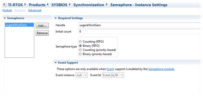
Note that the newly created semaphore `urgentWorkSem` is already available in the global namespace. No need to do anything special to get access to it in the source file.
Using a Semaphore
---------------------------------
* Go to the TI-RTOS install directory and open `docs/Documentation_Overview_cc13xx_cc26xx.html`
* Open up the TI-RTOS Kernel User Guide
* Look up `Semaphore` under `Synchronization Modules` in the User's Guide and find out how to post to, and pend on, the Semaphore you just created
* Rewrite the code so that the HWI only post the semaphore to which the `urgentWorkTask` is pending on
* If you press the button several times, can we handle that now? Why?
* Change the `Semaphore` to be a counting semaphore
* What about now, does it work?
Execution graph example
------------------
In the image below you can see the result of the event logging when all of the above is implemented, and the button is pressed while the `workTaskFunc` is running.
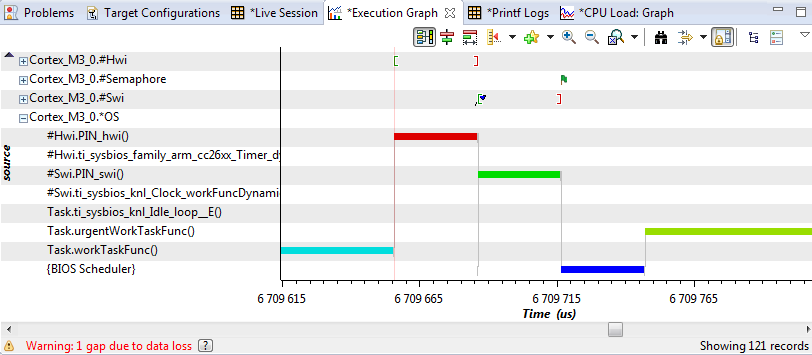
What you are seeing here:
* `workTaskFunc` running merrily, pretending to do something useful
* Pin interrupt (Hwi) occurring, which posts a Swi to do deferred processing of the interrupt
* Pin Swi running (via BIOS Scheduler), which calls your `pinInterruptHandler` which posts to the semaphore (flag icon)
* BIOS Scheduler deciding that the `urgentWorkTaskFunc` is no longer blocked and has higher priority so should run
* `urgentWorkTaskFunc` running.
When you have implemented a counting semaphore, you should see the urgentWorkTaskFunc running longer (if you press more), and pending on the semaphore until it's out of produced events.
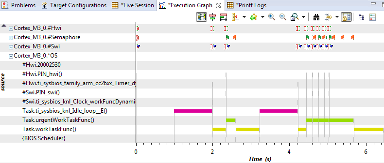
Note the single button press first, and then several button presses which increase the count on the semaphore. The three flags at the end are easy to see and are `Semaphore_pend` calls made by the thread to see if it has anything more it should do. Which it does until the last flag, which is where the task becomes blocked on `urgentWorkSem` and BIOS transfers control to a lower priority task.
Epilogue
==================================
This first lab has given a quick hands on in how to use the some of the debugging facilities, two different threads (Tasks, HWI), Semaphores as well as some of the general TI-RTOS core APIs.