Introduction
==================================
This training will show you how to create and integrate a basic Sensor Controller ADC driver with a blank TI-RTOS project. The training is expected to take about 2h to complete, and requires little knowledge about the subject, except some familiarity with embedded programming.
The ADC driver will measure an input voltage on one of the pins. To vary the input voltage applied to the pin, an external voltage source can be connected to the analog input pin. As an alternative, a jumper or wire from the LaunchPad can be used. For this training, a jumper from the LaunchPad is used to short the analog input pin with an adjacent pin.
Prerequisites
==================================
Completed material
---------
* TI-RTOS Basics Lab 1
* SC Studio Basics
* For bonus task:
* BLE Basics
* Prop RF Basic RX and TX
Software for desktop development
---------
* [Code Composer Studio 6.1.3+][CCS DL]
* [Sensor Controller Studio 1.3.0+][SCS DL]
* [TI-RTOS 2.20.01.08+][TI-RTOS DL]
* For bonus tasks:
* [TI BLE SDK 2.2.1][TI BLE SDK]
* TI BLE Project Zero smart phone app
* [SmartRF Studio 7+][SMARTRF STUDIO]
[CCS DL]: https://www.ti.com/tool/ccstudio
[SCS DL]: https://www.ti.com/tool/SENSOR-CONTROLLER-STUDIO
[TI-RTOS DL]: https://www.ti.com/tool/ti-rtos-mcu
[TI BLE SDK]: https://www.ti.com/tool/ble-stack
[SMARTRF STUDIO]: https://www.ti.com/tool/smartrftm-studio
Hardware
---------
* 1x [CC2650][CC2650 LP] or [CC1350][CC1350 LP] LaunchPad
* Micro-USB Cable for LaunchPad
* External variable voltage source, OR
* Wire or jumper, see [Task 0](#task-0-ndash-hardware-setup)
* For bonus tasks:
* 1x [CC2650 LaunchPad][CC2650 LP] (for Bonus Task 1)
* 2x [CC1350 LaunchPad][CC1350 LP] (for Bonus Task 2)
[CC2650 LP]: https://www.ti.com/tool/launchxl-cc2650
[CC1350 LP]: https://www.ti.com/tool/launchxl-cc1350
Abbreviations / terminology
==================================
| Abbreviation / terminology | Definition
|----------------------------|------------
| CCS | Code Composer Studio
| SC | Sensor Controller
| SCS | Sensor Controller Studio
| LP | LaunchPad
| AUX RAM | Sensor Controller memory domain
| RTC | Real-time Clock
| RTOS | Real-time Operating System
| TI-RTOS | RTOS for TI microcontrollers
----------------------
Task 0 – Hardware setup
===================
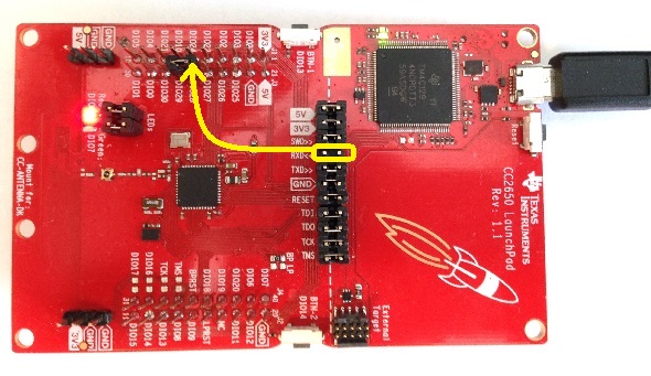
Connect the CC1350/CC2650 LaunchPad to your computer via the micro-USB cable. `DIO29` on LaunchPad will be the ADC input. Connect the external variable voltage source to `DIO29`. As an alternative, a jumper or wire can be used. In this training `DIO29` is connected to `DIO28` or `DIO30` via a jumper, borrowed from `RXD<<` on the LaunchPad. `DIO28` will be set as digital output high and `DIO30` as digital output low, which will be used to test and verify the ADC driver and main application. Note that any jumper that does not interfere with the application can be used. See picture below for reference.
----------------------
Task 1 – Import, build and download clean TI-RTOS Project
==================================
In this task you will import a clean TI-RTOS project called `Empty (Minimal) Project` and run the program on your LaunchPad. This project will be used as a clean template to integrate the SC driver. It is a minimal TI-RTOS example project that has one single task that toggles the red LED on the LaunchPad once every second.
[[+b How to find your CCS workspace path
1. In CCS, go to `Project → Properties`, or press <kbd>Alt+Enter</kbd>.
2. Click on `Build` section to the left.
3. Navigate to the `Variables` tab.
4. Click on `Show system variables` checkbox at the bottom.
5. Scroll down until you find the `WORKSPACE_LOC` variable, and note the value. This is your CCS workspace path for your project.
+]]
Do the following:
1. Open CCS and expand the Resource Explorer window, done by clicking on `View → Resource Explorer` seen in the picture below.

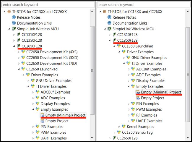
2. Import the `Empty (Minimal) Project` found in Resource Explorer, under the `TI-RTOS for CC13XX and CC26XX` package. See picture below for reference.
* If you are using CC2650, use left navigation.
* If you are using CC1350, use right navigation.
3. Build and download the project to your LaunchPad by pressing <kbd>F11</kbd>. Then press <kbd>F8</kbd> to allow the program to run. The red LED should now toggle once every second.
[[y! If you failed to download and run the "Empty (Minimal) Project"
* Make sure you have connected the LaunchPad to your computer with a micro-USB Cable.
* Make sure that you have selected the correct project
* called `empty_CC2650_LAUNCHXL_TI_CC2650F128` for CC2650.
* called `empty_CC1350_LAUNCHXL_TI_CC1350F128` for CC1350.
* Unplug and plug in the USB cable again.
* You can try to run a forced mass erase operation with Smart RF Flash Programmer 2 and then try again.
]]
----------------------
Task 2 – Create and setup SCS project
==================================
In this task we will create a new Sensor Controller project in SCS.
[[b! SCS Documentation and Help
At any time in SCS, `Help → Sensor Controller Studio Help` or press <kbd>F1</kbd> for documentation and help.
]]
Create SCS project
---------------------
Do the following:
1. Start SCS and open a new project, `File → New Project` or <kbd>Ctrl+N</kbd>.
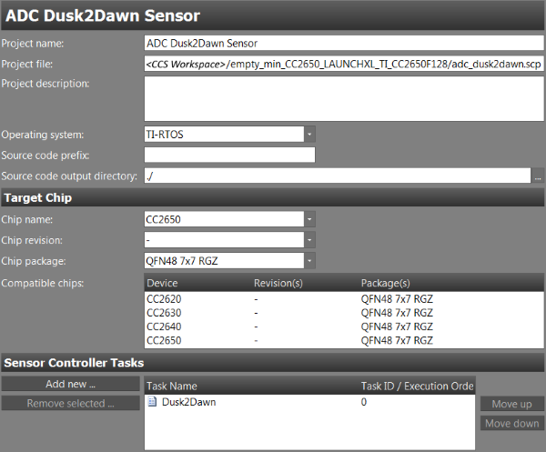
* Set the `Project Name` to `ADC Dusk2Dawn Sensor`.
* Set the `Operating system` to `TI-RTOS`.
* Set `Source code output directory` to `./`.
* Set `Chip name` to
* `CC2650` if using CC2650.
* `CC1350` if using CC1350.
* Set `Chip package` to `QFN48 7x7 RGZ`.
* Add one task by clicking `Add new`, name it `Dusk2Dawn`.
* Save the project, `File → Save Project` or <kbd>Ctrl+S</kbd>, to the CCS project base folder in your CCS workspace. See [Task 1](#task-1-ndash-import-build-and-download-clean-ti-rtos-project) on how to find your CCS workspace path.
[[r! Correct project file save path
The path set in `Project file` **must** be the project base folder located in the CCS workspace. If not, then the output code generation will be wrong. As an alternative, the `Source code output directory` can be set to the absolute base folder path in the CCS project.
]]
See picture below of how it should look.
Setup Dusk2Dawn driver
-------------
### Dusk2Dawn task properties
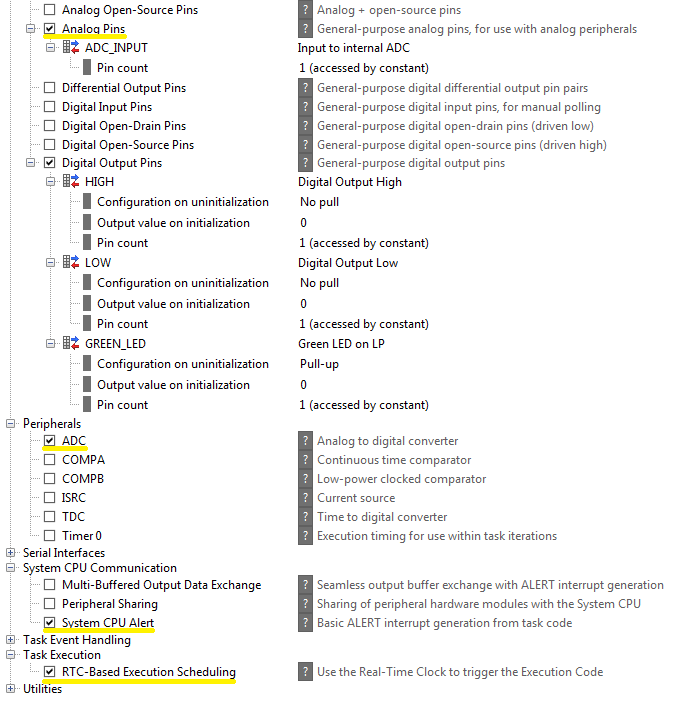
We need to specify the resources to be used. Go to `Task Properties` for the Dusk2Dawn task, which can be accessed by clicking on the task name in the directory on the left hand side, above the `Initialization Code`. Select the task resources in the list below.
* **Analog Pins**
* Create one pin and name it `ADC_INPUT`.
* **Digital Output Pins**
* Create three pins and name them `GREEN_LED`, `LOW`, and `HIGH`. You can add more pins by clicking `Add I/O usage` to the right of the task resource name.
* **ADC**
* **System CPU Alert**
* **RTC-Based Execution Scheduling**
[[b! Unnecessary pins
If you are using an external variable voltage source connected to the ADC input, then the two digital pins `LOW` and `HIGH` are not needed.
]]
Make sure the `Task resource` settings match the screenshot below:
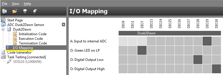
### Dusk2Dawn I/O mapping
Go to the `I/O Mapping` window and set the following pins to:
* Analog pin `ADC_INPUT` to `DIO29`.
* Digital pin `GREEN_LED` to `DIO7`.
* Digital pin `LOW` to `DIO28`.
* Digital pin `HIGH` to `DIO30`.
[[b! Unnecessary pins
Same applies here, if you are using an external variable voltage source connected to the ADC input, then the two digital pins `LOW` and `HIGH` are not needed.
]]
The pin order can vary. It should look something like the picture below.
----------------------
Task 3 – Create sensor controller ADC driver
==================================
In this task we are implementing the ADC driver, as well as testing it to verify it works. We also look at the different aspects with the SCS, including coding, testing, and debugging.
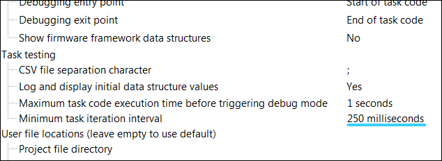
Specifying the RTC period
---------------
The RTC period is specified by `Minimum task iteration interval` in preferences, `File → Preferences` or <kbd>Ctrl+P</kbd>. See picture below for reference. A RTC period of `250 milliseconds` is more than enough for this training.
[[y! Task testing specific
Specifying the RTC period in SCS **only** affects the task testing in SCS. This does not set the RTC period when the SC driver is integrated into other projects or applications, as this is done through the functions `scifStartRtcTicks()` and `scifStartRtcTicksNow()`.
]]
### RTC scheduling
The RTC period determines the execution interval of the SC task, if the SC task is scheduled by the RTC with the `fwScheduleTask()` function. `fwScheduleTask(N)` schedules the next task iteration in `N` RTC ticks. So for instance, let's say the RTC is operating at 200Hz. Scheduling the SC task with `fwScheduleTask(1);` would run the execution code at a 200Hz rate. With `fwScheduleTask(5);` the execution code would run at a (200/5)=40Hz rate, and so on.
However, to minimize current consumption it is recommended to select the highest possible tickPeriod so that the delay for `fwScheduleTask()` can be as low as possible.
[[d-question-sign Quiz
If a given SC task is scheduled with `fwScheduleTask(2);`, and the RTC period is set to 250 ms, what is the SC task period?
[quiz]
x> 125 ms --> Not possible in this configuration
x> 250 ms --> Would work with `fwScheduleTask(1);`
v> 500 ms --> 2 \* 250 ms = 500 ms
x> 1000 ms --> Would work with `fwScheduleTask(4);`
[quiz]
If a SC task period is 700 ms, and the RTC is set at 20 Hz, for which `N` is the SC task scheduled with the function `fwScheduleTask(N);`?
[quiz]
x> N=7 --> Task period would be 350 ms
x> N=10 --> Task period would be 500 ms
v> N=14 --> 20 Hz\*14 = (1000/20) ms\*14<br>= 50 ms\*14 = 700 ms
x> N=20 --> Task period would be 1000 ms
[quiz]
If a SC task is scheduled with `fwScheduleTask(3);`, and the SC task period is 1500 ms, what is the RTC period?
[quiz]
v> 2 Hz --> 1500 ms / 3 = 500 ms = 2 Hz
x> 3 Hz --> Task period would be 1000 ms
x> 5 Hz --> Task period would be 600 ms
x> 6 Hz --> Task period would be 500 ms
[quiz]
]]
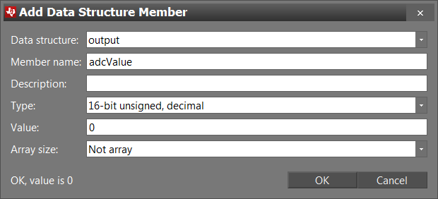
Adding a data structure member
---------------
For a given SC Task, data structure members are used in a SC task to store variables in AUX RAM. This allows the SC Task to store data between task iterations, and to exchange data between the SC and the TI-RTOS application. There are four different types of data structures that represent different types of data, shown in the table below. Even though the structures have intended uses, it is not required to be followed.
Data structure | Intended use
---------------|--------------
cfg | Configuration of SC Task
input | Input data for SC Task
output | Output data from SC Task
state | Internal state of SC Task
To add a data structure member, locate the `Data structures` box to the right in either code window. This is the same for both `Initialization Code`, `Execution Code`, and `Termination Code`. Click `Add`. Select which `Data structure`, and set `Member name` and `Value`. Optionally, but not necessary, give a `Description` and choose a `Type`. See example picture for ADC output value below.
[[d-question-sign Quiz
A SC Task is keeping track of how many ADC readings it has done between each task iteration. In which data structure should the variable be placed in?
[quiz]
x> cfg
x> input
x> output
v> state
[quiz]
A SC task is set to notify the main application when a given threshold is crossed, determined by the main application. In which data structure should the threshold be placed in?
[quiz]
v> cfg
x> input
x> output
x> state
[quiz]
]]
Implement the ADC driver
-------------
It is time to create the ADC driver. The application will simulate a dusk to dawn sensor that will turn on the green LED after dusk and turn it off after dawn. The SC will alert the main application when a transition from dawn to dusk or vice versa occurs, and the main application will turn on or off the red LED if the it is dawn or not.
The dusk to dawn simulation is done by comparing the analog sensor value to a given threshold. The threshold is specified by the main application, stored in a cfg structure data member. Being under or above the threshold sets the state to be either dusk or dawn, respectively. The state is stored in a state structure member. The analog sensor value is sampled by the ADC and stored in an output structure data member.
[[y! Create data structure members
You need to create three data structure members: `threshold` in cfg structure, `adcValue` in output structure, and `dawn` in state structure. See [Task 2](#adding-a-data-structure-member) on how to create data structure members.
]]
### Initialization code
The initialization code will run once when the task is started by the TI-RTOS application. The initialization code should set the digital values for the `HIGH` and `LOW` pins, select the sampling pin for the ADC, and schedule the first execution of the execution code to the next RTC tick. See [Task 2](#specifying-the-rtc-period) for a more detailed explanation on how RTC scheduling and how `fwScheduleTask()` works.
The initialization code is presented below. Copy and paste the code snippet into the `Initialization Code` in SCS.
```c
// Set `DIO28` High
gpioSetOutput(AUXIO_O_HIGH);
// Set `DIO30` Low
gpioClearOutput(AUXIO_O_LOW);
// Select ADC input
adcSelectGpioInput(AUXIO_A_ADC_INPUT);
// Schedule the first execution
fwScheduleTask(1);
``` Dusk2Dawn Initialization code
### Execution code
The execution code should enable the ADC, sample and store the ADC value, determine the state to be dusk or dawn by checking against the threshold, and alert the main application if a transition happens. As explained in [Task 2](#specifying-the-rtc-period), it is scheduled through the `fwScheduleTask()` function every RTC tick.
Copy and paste the code snippet below into the `Execution Code` in SCS. **Note**: There is an intentional error in the code, see next section.
```c
// Enable the ADC
adcEnableSync(ADC_REF_FIXED, ADC_SAMPLE_TIME_2P7_US, ADC_TRIGGER_MANUAL);
// Sample the analog sensor
adcGenManualTrigger();
adcReadFifo(output.adcValue);
// Disable the ADC
adcDisable();
U16 oldState = state.dawn;
if (input.adcValue > cfg.threshold) {
state.dawn = 1; // Dawn
gpioClearOutput(AUXIO_O_GREEN_LED);
} else {
state.dawn = 0; // Dusk
gpioSetOutput(AUXIO_O_GREEN_LED);
}
if (oldState != state.dawn) {
// Signal the application processor.
fwGenAlertInterrupt();
}
// Schedule the next execution
fwScheduleTask(1);
``` Dusk2Dawn Execution Code
### Termination code
The termination code will run once when the SC task is either terminated by the main application, or executed without scheduling. The main purpose for the termination code is to do necessary cleanup, such as releasing or resetting crucial resources.
For this task, there is no necessary cleanup, and the termination code is therefore left empty.
Dusk2Dawn code error
-----------------
With the Dusk2Dawn driver implemented, it is time for testing. However, nobody makes perfect code. In the code given above there is a subtle syntax error. By first glance it is not obvious where the error is, but SCS can help. Go to the `Task Testing` window, `View → Task Testing` or <kbd>Ctrl+T</kbd>. Select the `ADC Dusk2Dawn Sensor` project if this is not already set.
You should now be present with an event log, such as the picture below. It shows the different stages of validating and compiling the project. This event log is only shown in [this window]{And also in the<br>`Code Generation` window} when something went wrong during validation and compiling. As we see at the bottom of the log, during compilation of the execution code, it encountered a syntax error at line 12. Note that the line number can vary. See picture below for reference.
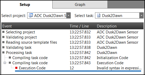
So, go back to the execution code window and find the specified line number. If you are observant, you should see that the code line
```c
if (input.adcValue > cfg.threshold) {
```
is accessing the `adcValue` from the **input** structure, and not the **output** structure. A subtle bug indeed. Fix the line by changing input to output.
Now, when going back to the `Task Testing` window, the event log should no longer be there and you should be presented with the actual `Task Testing` screen.
[[r! More code errors?
If you got more syntax errors present, then you might have forgotten to create or name the pins correctly in the `Task Properties` window, or to create or name the data structure members in the code windows. Go back and double check.
]]
Dusk2Dawn task testing
-----------------
Now we test the task to verify it works as intended. Do the following:
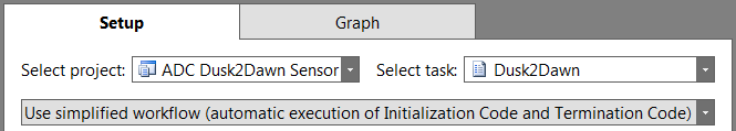
1. Go to the `Task Testing` window if not already there, `View → Task Testing` or <kbd>Ctrl+T</kbd>.
* Select the `ADC Dusk2Dawn Sensor` project if not already set.
* Select the `Use simplified workflow`. See picture below.
* Add `Run Execution Code` to the `Task iteration action sequence`.

* Click on `Connect` <kbd>F12</kbd>. You should now be in the graph tab.

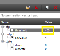
* On the right side of the graph window you should find all data structure members created. If there are no variables you might have forgotten to create it during coding. Configure the `cfg.threshold` value by double clicking the variable, set it to 400, and press <kbd>Enter</kbd>.
* Then, click `Run Task Iterations Continuously` <kbd>F5</kbd>.

* Select `output.adcValue` in the member struct box. A graph of the variable should appear.
* Place the wire or jumper between `DIO29` and `DIO30`. The `output.adcValue` should be [high]{around 3160} and `state.dawn` should be 1, indicating it is dusk. Now move the wire or jumper between `DIO28` and `DIO29`. The `output.adcValue` should drop down to about 0 and `state.dawn` should be 0, indicating it is dawn. The green LED should also turn on. See the picture below on what you should observe.

* When you are content that the driver is working, click `Disconnect` <kbd>F11</kbd>.

Dusk2Dawn code generation
-----------------
Now that everything is working well, the next step is to generate code from the SCS project.
Do the following:
1. Go to the `Code Generator` window, `View → Code Generator` or <kbd>Ctrl+G</kbd>.
* Select Dusk2Dawn as `Current project`.
* Either select `Output automatically` to auto generate code each time visiting the window, or click `Generate driver source code`.
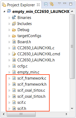
* Click `View output directory` and **double check** it is the project base folder of the `Empty (Minimal) Project`. The files should also be visible in the project explorer in CCS, shown in the picture below. Try refreshing the project <kbd>F5</kbd> if they do not show up.
* Build the project and see that it compiles without errors.
[[r! Generated files do not appear in CCS project folder
If no files are generated during code generation, then the output directory is most likely wrong. Go back to project settings and make sure `Project file` and `Source code output directory` path are correct. See [Task 2](#create-scs-project) for help.
]]
-----------------
Task 4 – Implement TI-RTOS application
==================================
Now we will write the TI-RTOS application and integrate the sensor controller driver you created in [Task 3](#task-3-ndash-create-sensor-controller-adc-driver). This task will show you how to communicate with the SC, and the different ways to process the SC data, with focus on execution context.
Code documentation regarding the SC can be found at
* `scif_framework.h` file from code generation.
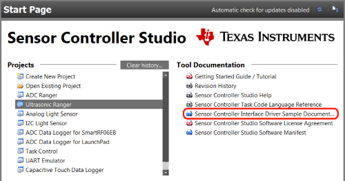
* SC Interface documentation (doxygen), found on the start page.
### Refactoring and cleanup
We are renaming the `heartBeatFxn()` function in the `empty_min.c` file for a more descriptive and relevant name for this project. Refactor the function to `dusk2dawnFxn()`, by right click function and `Refactor → Rename...`, or click function and <kbd>Alt+Shift+R</kbd>.
Also, replace the [main loop]{Refering to the</br>`while(1){}` loop} in the newly renamed `dusk2dawnFxn()` function with an empty loop `while (1) {}`. This is because it toggles the [green LED]{`Board_LED1`}, which will interfere with our application.
### I/O configuration
The green LED is controlled by the SC. Because of this the TI-RTOS application PIN Driver must not initialize and open the green LED pin. To fix this, go to CCS and comment out the `Board_LED1` line in the `ledPinTable` struct, located in the `empty_min.c` file. See code snippet below for reference.
```c
/*
* Application LED pin configuration table:
* - All LEDs board LEDs are off.
*/
PIN_Config ledPinTable[] = {
Board_LED0 | PIN_GPIO_OUTPUT_EN | PIN_GPIO_LOW | PIN_PUSHPULL | PIN_DRVSTR_MAX, // Red LED on Launch Pad
//Board_LED1 | PIN_GPIO_OUTPUT_EN | PIN_GPIO_LOW | PIN_PUSHPULL | PIN_DRVSTR_MAX, // Green LED on Launch Pad
PIN_TERMINATE
};
``` Updated LED pin table
SC driver interaction and processing
--------------------
There are two aspects with SC interaction and processing that needs to be addressed before implementation: how the SC and main application interact, and how to exchange data.
### SC interaction
SC interaction is exclusively intended to be done through the two interrupt callbacks `Control READY` and `Task ALERT`. This way the SC can signal the main application at appropriate times.
The `Control READY` interrupt is signaled when one of the non-blocking task control functions, such as `scifStartTasksNbl()`, has executed successfully on the SC. However, the interrupt is encapsulated in the `scifWaitOnNbl()` function, and is in most cases, such as this training, not necessary to handle.
The `Task ALERT` interrupt is signaled when a SC task calls one of the functions `fwGenAlertInterrupt()`, `fwGenQuickAlertInterrupt()` or `fwSwitchOutputBuffer()`, as seen done in [Task 3](#implement-the-adc-driver). This interrupt is used to signal the main application when some type of computation is finished, or some event has happened. This is what is interesting for us, as this allows us to free the main application from waiting for the SC driver to finish or some certain SC event to happen.
In the SC initialization part for this project, we handle both signals by registering a callback for each interrupt. This is only done for the sake of completeness. As only the `Task ALERT` signal is of importance for this project, we are only processing that signal.
[[d-question-sign Quiz
Which interrupt signal(s) is associated with the task control function `scifStopTasksNbl()`, issued from the main application?
[quiz]
x> None
x> Task ALERT --> Only SC tasks can generate this signal
v> Control READY
x> Both
[quiz]
Which interrupt signal(s) can a SC Task explicitly generate through function calls?
[quiz]
x> None
v> Task ALERT
x> Control READY --> This is handled by the SC
x> Both
[quiz]
]]
### SC task data structure
See [Task 3](#adding-a-data-structure-member) for an overview of the data structures.
Accessing data stored in the SC AUX RAM can be done in two ways: either direct or indirect access. Which type of access is determined by the type of data structures used: single or multi-buffered. The only requirement is for multi-buffered data, where only indirect access can be used. Single-buffered can use either way. However, direct access is preferred as this is much faster.
Direct access in done through the variable `scifTaskData` structure, defined in `scif.h`. The hierarchy in which the data structure members are stored are as such: `scifTaskData` as base, next is the name of the SC task in camelCase, then the type of the data structure, and lastly the name of the data structure member.
For instance, the data structure member `adcValue`, located in the `output` structure, defined in the SC task `ADC`, is accessed as such: `scifTaskData.adc.output.adcValue`. For a complete view of the `scifTaskData` structure, see the `scif.h` file.
The hierarchy and structure of the `scifTaskData` struct is highly dependent on the SC task implementation, and will vary from SC driver to SC driver.
Indirect access can be done through the `Task data structure access` functions defined in the `scif_framework.h` file, mainly by the `scifGetTaskStruct` function. By specifying the SC Task ID and the structure type, the relevant structure pointer is returned. As mentioned, this must be used to access multi-buffered data structures.
[[d-question-sign Quiz
A data structure member is defined in a SC Task, and is called `counter`. It is stored in the `output` structure. The SC Task is called `Pin Counter`. What is the resulting direct access code?
[quiz]
x scifTaskData.output.pinCounter.counter
x scifTaskData.pinCounter.counter.output
v scifTaskData.pinCounter.output.counter
[quiz]
]]
Initialize and setup of SC driver
-----------------
To initialize and setup the SC driver a couple of necessary steps need to be done. First, add
```c
#include "scif.h"
#define BV(x) (1 << (x))
``` Scif header and macro
at the top of the `empty_min.c` file. The `scif.h` file is the main interface to the SC driver compiled and generated from the SCS project. `BV()` is a bit vector macro, which will be useful soon.
### Create callback functions
The initialization code for the SC driver uses two callback functions to handle the two interrupt signals `Task ALERT` and `Control READY`. Therefore, copy and pase the code snippet above the `dusk2dawnFxn()`, shown below.
```c
void scCtrlReadyCallback(void)
{
} // scCtrlReadyCallback
void scTaskAlertCallback(void)
{
} // scTaskAlertCallback
``` SC callback functions
### Initialize driver and register callbacks
Then, in the `dusk2dawnFxn()`, before the main loop `while (1) {`, copy and paste the following code snippet. It is important to note that the initialization code should preferrably be run in a TI-RTOS context, such as a task context.
```c
// Initialize the Sensor Controller
scifOsalInit();
scifOsalRegisterCtrlReadyCallback(scCtrlReadyCallback);
scifOsalRegisterTaskAlertCallback(scTaskAlertCallback);
scifInit(&scifDriverSetup);
// Set the Sensor Controller task tick interval to 1 second
uint32_t rtc_Hz = 1; // 1Hz RTC
scifStartRtcTicksNow(0x00010000 / rtc_Hz);
// Configure Sensor Controller tasks
scifTaskData.dusk2dawn.cfg.threshold = 600;
// Start Sensor Controller task
scifStartTasksNbl(BV(SCIF_DUSK2DAWN_TASK_ID));
``` SC Driver Initialization
So what does the code do? Let's study each code line.
```c
// Initialize the Sensor Controller
scifOsalInit();
scifOsalRegisterCtrlReadyCallback(scCtrlReadyCallback);
scifOsalRegisterTaskAlertCallback(scTaskAlertCallback);
scifInit(&scifDriverSetup);
``` Driver specific initialization
The first line simply initializes the [OSAL]{Operating System Abstraction Layer} of the `scif` framework. The next two lines registers two callbacks for the two interrupt signals `Control READY` and `Task ALERT` from the SC. This is how the main application can communicate and work together with the SC, explained in the [Section](#sc-interaction) above. The fourth line initializes the SC with our SC task driver created in [Task 3](#task-3-ndash-create-sensor-controller-adc-driver).
```c
// Set the Sensor Controller task tick interval to 1 second
uint32_t rtc_Hz = 1; // 1Hz RTC
scifStartRtcTicksNow(0x00010000 / rtc_Hz);
``` RTC initialization
The next line configures the RTC tick interval. This is more thoroughly explained in [Task 3](#specifying-the-rtc-period).
For this training we are setting the RTC interval to 1 second. However, feel free to play around with the RTC interval by modifying the `rtc_Hz` variable or the function argument directly. The function `scifStartRtcTicksNow()` takes a 32-bit value as an argument. The argument represents a tick interval, where bits 31:16 are the seconds, and bits 15:0 are the 1/65536 of a second.
```c
// Configure Sensor Controller tasks
scifTaskData.dusk2dawn.cfg.threshold = 600;
// Start Sensor Controller task
scifStartTasksNbl(BV(SCIF_DUSK2DAWN_TASK_ID));
``` Task initialization
Next line is the SC task configuration. This part is optional, and can be done at multiple appropriate times depending on the SC task. We configure the `cfg.threshold` variable, just as we did in [Task 3](#dusk2dawn-task-testing). The SC task configuration can practically be done at any time in the main application, but is highly recommended to be done at appropriate times, such as during initialization or before SC task execution.
The last line starts the actual execution of the SC task. All `scif` functions handling task IDs, such as `scifStartTasksNbl()`, takes a bit vector as an argument. The macro `BV()` performs this transformation, and this is why it was included. The SC Task IDs can be found in the generated `scif.h` file.
[[d-question-sign Quiz
Which statement(s) are true?
[quiz_multi]
x One can only set a cfg data member before the SC task is started. --> This can be done at any time.
x One must register callbacks for both the Control READY and Task ALERT signals. --> This is optional for both of them.
v RTC does not always have to be configured with the scifStartRtcTickNow() function. --> RTC only needs to be configured if Execution code is used, i.e. not needed for Event handler code.
v Multiple SC tasks can be started and operate at the same time. --> Supported by the SC.
[quiz_multi]
]]
Implement SC driver application processing
--------------
Now we can begin implementing the SC processing. We will do this in increments, implementing it in different application contexts and methods, and at the end discuss the pros and cons for each solution.
All three solutions are interrupt based, where the idea is the same:
1. Wait for a `Task ALERT` signal.
* Clear the interrupt source.
* Process the SC task.
* Acknowledge the ALERT event to the scif framework.
The actual task processing shall be encapsulated in a function called `processTaskAlert()`. Copy and paste the code shown below.
```c
void processTaskAlert(void)
{
// Clear the ALERT interrupt source
scifClearAlertIntSource();
// Do SC Task processing here
// Acknowledge the ALERT event
scifAckAlertEvents();
} // processTaskAlert
``` SC Task Alert Handling
The processing is simple: fetch the `state.dawn` variable, and set the LED0 pin to that value. See [Task 4](#sc-task-data-structure) on how to access SC data. Copy and paste the code snippet below in `processTaskAlert()` above, where the SC task processing is marked.
```c
// Fetch 'state.dawn' variable from SC
uint8_t dawn = scifTaskData.dusk2dawn.state.dawn;
// Set LED0 to the dawn variable
PIN_setOutputValue(ledPinHandle, Board_LED0, dawn);
``` Dusk2Dawn processing
This will not run just yet, as we need to connect the processing to the interrupt signal. Below are the three different solutions presented.
### Solution 1 – HWI
For the first solution the SC task alert handling and processing will be done in the `scTaskAlertCallback()` function. The `scTaskAlertCallback()` is executed in a HWI context, as the title suggests. So in `scTaskAlertCallback()`, call the `processTaskAlert()` function. See code snippet below.
```c
void scTaskAlertCallback(void)
{
// Call process function
processTaskAlert();
} // scTaskAlertCallback
``` HWI SC Task alert process
Build and debug the project. Move the wire or jumper between `DIO28` and `DIO30` on the LaunchPad. You should see the green and red LED toggle in-between each other.
The application is now doing nothing until the SC task generates a `Task ALERT` signal. The HWI callback `scTaskAlertCallback()` is then called. In the HWI context the callback clears the interrupt source, fetches the dawn state, sets the LED0 value, and acknowledges the ALERT event.
### Solution 2 – SWI
Doing extensive processing in a HWI process is not advised, as it blocks other high priority processes while running. For this solution, we will move the processing to a SWI process, and the HWI process will signal the SWI process.
At the top of the `empty_min.c` file, add the following
```c
#include <ti/sysbios/knl/Swi.h>
// SWI Task Alert
Swi_Struct swiTaskAlert;
Swi_Handle hSwiTaskAlert;
void swiTaskAlertFxn(UArg a0, UArg a1)
{
// Call process function
processTaskAlert();
} // swiTaskAlertFxn
``` SWI variables and function
In the `main()` function, before `BIOS_start()` is called, add the following code snippet to initialize the SWI process.
```c
// SWI Initialization
Swi_Params swiParams;
Swi_Params_init(&swiParams);
swiParams.priority = 4; // Must be bigger than 1, which is the main task pri
Swi_construct(&swiTaskAlert, swiTaskAlertFxn, &swiParams, NULL);
hSwiTaskAlert = Swi_handle(&swiTaskAlert);
``` SWI initialization
Now, copy and paste the following into `scTaskAlertCallback()`. Whenever the `Task ALERT` signal is raised, the HWI callback will signal the SWI process, where the entirety of the processing will be done.
```c
void scTaskAlertCallback(void)
{
// Post a SWI process
Swi_post(hSwiTaskAlert);
} // scTaskAlertCallback
``` SWI signalling
Again, build and debug the project. Move the wire or jumper on the LaunchPad. You should observe the same behavior from the HWI solution.
But why was this whole process of moving the task processing to SWI context necessary if the behavior was the same? This would be much more obvious if the actual task processing was much more extensive computational wise. The current task is substantially small, and therefore will not impact the execution whatever the context it runs in. It is still advised to run the task processing at least in SWI context.
### Solution 3 – Task
Next solution is to move the processing in a task context. The idea is to signal the main task when the HWI is run, and then in turn run the processing in the task. We will use a Semaphore to synchronize the signaling.
[[y! SWI code no more needed
The SWI relevant code, such as the struct and handle variables, `swiTaskAlertFxn()` function, and initialization, is no more needed for this training and can be removed if desirable. This does **not** include the `processTaskAlert()` function.
]]
First up, at the top of the `empty_min.c` file, add the relevant header file and variables.
```c
#include <ti/sysbios/knl/Semaphore.h>
// Main loop Semaphore
Semaphore_Struct semMainLoop;
Semaphore_Handle hSemMainLoop;
``` Semaphore variables
Next, in `main()` before `BIOS_start()` is called, initialize the semaphore struct and store the handle.
```c
// Semaphore initialization
Semaphore_Params semParams;
Semaphore_Params_init(&semParams);
Semaphore_construct(&semMainLoop, 0, &semParams);
hSemMainLoop = Semaphore_handle(&semMainLoop);
``` Semaphore initialization
Now, in the `scTaskAlertCallback()` function, we will post to the Semaphore which should trigger the execution in main task.
```c
void scTaskAlertCallback(void)
{
// Post to main loop semaphore
Semaphore_post(hSemMainLoop);
} // scTaskAlertCallback
``` Semaphore signalling
Now in the main loop in `dusk2dawnFxn()`, we wait on the Semaphore indefinitely and afterwards call `processTaskAlert()`, see code snippet below.
```c
while (1) {
// Wait on sem indefinitely
Semaphore_pend(hSemMainLoop, BIOS_WAIT_FOREVER);
// Call process function
processTaskAlert();
}
``` Dusk2Dawn main loop
Build and debug the project. Move the wire or jumper on the LaunchPad. The same behavior again should be observed. This way of using the HWI process to signal a task process (or a SWI process in solution 2) is the way to go. Not only does it free up high priority processes, but it also streamlines the application processing, which is important in bigger applications.
Solutions summary
--------------------
We have now implemented and tested three different solutions.
**HWI Context**:
This gave us the fastest possible response time, as the actual processing was done as close to the `Task ALERT` signal as possible. However, this is never advised, as any HWI process should be kept to minimal execution time to not block other high priority process from executing.
**SWI Context**:
This solution does not have as fast response time as the HWI solution, since the HWI process must signal the SWI process. This is however still much preferred over the HWI solution, as it does not block other high priority processes. Some extra code size is to be expected.
**Task Context**:
This solution has a slightly slower response time than the SWI context, but again does not block other high priority processes. The biggest advantage is that the processing can be much bigger computational wise. It also scales much better with increasingly more complex projects.
All in all, the Task solution is the preferred solution in most cases. Solution two is also a viable method. It is flexible, scalable with complex projects, can handle computational heavy processing, enables power saving, and does not cause starvation among high priority processes.
[[d-question-sign Quiz
Which context(s) gives the fastest response time?
[quiz_multi]
v> HWI
x> SWI
x> Task
[quiz_multi]
Which context(s) are preferred for computational heavy processing?
[quiz_multi]
x> HWI
v> SWI --> Is OK in most cases
v> Task
[quiz_multi]
Which context(s) is the **least** preferred solution?
[quiz_multi]
v> HWI
x> SWI
x> Task
[quiz_multi]
]]
------------------
Bonus Tasks 1 – Integrate with BLE
==================================
In this training, we are porting our simple application into the BLE project `Project Zero`. It is meant to show you how the application would operate within a bigger and more complex project. We are going to use the already existing service `Data Service` to communicate which state of dawn or dusk it currently is.
[[y! Hardware requirement
This bonus task requires a CC2650 LaunchPad.
]]
Import and modify Project Zero
-----------------
First, import a fresh version of `Project Zero App` from the Resource Explorer in CCS, as well as `Project Zero Stack`. It can be found in the `SimpleLink Academy` package, under the `Bluetooth low energy` section. Expand box below for reference.
[[+y Resource Explorer: Project Zero App and Stack project path
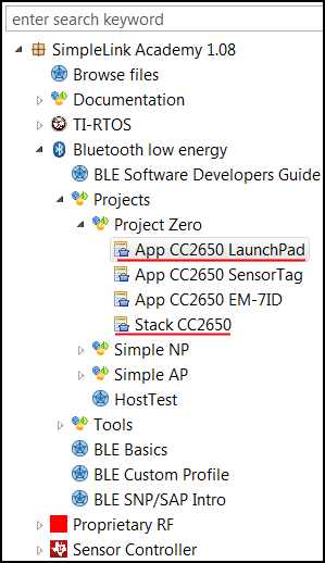
+]]
Do the following:
* Copy and paste all 6 `scif` related code files from the `empty_min` project into the `Application/` folder in `Project Zero`.
* Open the `project_zero.c` file.
* Add `#include "scif.h"` at the top.
* Add `APP_MSG_SC_CTRL_READY` and `APP_MSG_SC_TASK_ALERT` enum in the `app_msg_types_t` enum typedef.
* Find the `ledPinTable[]` array. Comment out the `Board_LED1` member. Remember that this is the LED that the SC task controls.
* Add the following function declarations
```c
// Dusk2Dawn functions
static void scCtrlReadyCallback(void);
static void scTaskAlertCallback(void);
static void processTaskAlert(void);
``` Dusk2Dawn Function Declarations
* Copy and paste the [SC Driver initialization](#initialize-and-setup-of-sc-driver) into `ProjectZero_init()`.
* In `user_processApplicationMessage()`, add the following case in the switch statement
* Note that a case for `APP_MSG_SC_CTRL_READY` is not added because we are not processing it.
```c
case APP_MSG_SC_TASK_ALERT:
processTaskAlert();
break;
``` Dusk2Dawn Switch Case
* Add the following functions
```c
static void scCtrlReadyCallback(void)
{
// Notify application `Control READY` is active
user_enqueueRawAppMsg(APP_MSG_SC_CTRL_READY, NULL, 0);
} // scCtrlReadyCallback
static void scTaskAlertCallback(void)
{
// Notify application `Task ALERT` is active
user_enqueueRawAppMsg(APP_MSG_SC_TASK_ALERT, NULL, 0);
} // scTaskAlertCallback
static void processTaskAlert(void)
{
// Clear the ALERT interrupt source
scifClearAlertIntSource();
// Get 'state.dawn', and set dawnStr to appropriate string
uint16_t dawn = scifTaskData.dusk2dawn.state.dawn;
char *dawnStr = (dawn != 0) ? "dawn" : "dusk";
// Set the dawnStr to the String characteristic in Data Service
DataService_SetParameter(DS_STRING_ID, strlen(dawnStr), dawnStr);
// Set red LED value
PIN_setOutputValue(ledPinHandle, Board_LED0, dawn);
// Acknowledge the ALERT event
scifAckAlertEvents();
} // processTaskAlert
``` Dusk2Dawn Functions
* Build and debug the project. The first build may take a while.
Test BLE device
----------------
To test our newly modified BLE device, do the following:
* Open up the TI BLE Project Zero smarth phone app.
* You should see a BLE device called `Project Zero` on the scanner list. Connect to the device.
* You should be presented with three services: LED, button and data service. The data service is where the dusk2dawn state is stored.
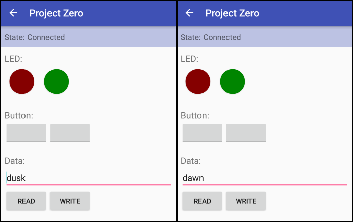
* Try to move the wire or jumper, and press the `READ` button. The dusk2dawn state should show up and change between the two states.
You should see something like the picture below. Note that the LED characteristic does not update, because we do not handle them.
-------------------
Bonus Tasks 2 – Integrate with Proprietary RF
==================================
In this training, we are again porting our simple application. However, now we are connecting it with Proprietary RF instead of BLE. We are modifying an already existing Proprietary Tx example project, called `RF Packet TX`. The application will be the transmitter, reading and storing the dawn state in a RF packet, while the second device will be the receiver, using SmartRF Studio to listen for the packet.
[[y! Hardware requirement
This bonus task requires **two** CC1350 LaunchPad; one for Tx and one for Rx.
]]
Import and modify RF Packet TX
-------------
First, import a fresh version of the project `RF Packet TX` from the Resource Explorer in CCS. It can be found in the `TI-RTOS for CC13XX and CC26XX` package. Expand box below for reference.
[[+y Resource Explorer: RF Packet TX project path
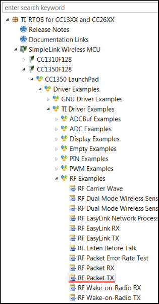
+]]
In CCS, do the following:
* Copy and paste all 6 `scif` related code files from `Empty (Minimal) Project` into the project base folder in `RF Packet TX`.
* Open up `rfPacketTx.c` in CCS.
* Copy and paste the following code snippet at the top of the file.
```c
#include <string.h> // strlen() and memcpy()
#include <ti/sysbios/knl/Semaphore.h>
#include "scif.h"
#define BV(x) (1 << (x))
Semaphore_Struct semMainLoop;
Semaphore_Handle hSemMainLoop;
``` Header Includes and Variable Declarations
* Go to the already existing `pinTable[]` array and change the first PIN instance from `Board_LED1` to `Board_LED0`. Remember that `LED1` is controlled by the SC.
* Copy and paste the SC callbacks.
```c
void scCtrlReadyCallback(void)
{
// Do nothing
} // scCtrlReadyCallback
void scTaskAlertCallback(void)
{
// Signal main loop
Semaphore_post(hSemMainLoop);
} // scTaskAlertCallback
``` SC Callbacks
* In `TxTask_init()`, add initialization for the semaphore
```c
// Main loop Semaphore initialization
Semaphore_Params semParams;
Semaphore_Params_init(&semParams);
semParams.mode = Semaphore_Mode_BINARY;
Semaphore_construct(&semMainLoop, 0, &semParams);
hSemMainLoop = Semaphore_handle(&semMainLoop);
``` Semaphore Initialization
* In `txTaskFunction()`, copy and paste the [SC Driver initialization](#initialize-and-setup-of-sc-driver) at the top of the function.
* At the bottom of `txTaskFunction()`, replace the whole main loop with the code below
```c
// Main loop
while(1) {
// Wait for signal
Semaphore_pend(hSemMainLoop, BIOS_WAIT_FOREVER);
// Clear the ALERT interrupt source
scifClearAlertIntSource();
// Get 'state.dawn', and set dawnStr to appropriate string
uint8_t dawn = scifTaskData.dusk2dawn.state.dawn;
char *dawnStr = (dawn != 0) ? "dawn" : "dusk";
uint16_t dawnStrLen = strlen(dawnStr);
// Populate packet, and set pktlen
packet[0] = (uint8_t)(seqNumber >> 8);
packet[1] = (uint8_t)(seqNumber++);
memcpy(packet + 2, dawnStr, dawnStrLen);
RF_cmdPropTx.pktLen = 2 + dawnStrLen;
// Send packet Tx
RF_runCmd(rfHandle, (RF_Op*)&RF_cmdPropTx, RF_PriorityNormal, NULL, 0);
// Toggle pin
PIN_setOutputValue(ledPinHandle, Board_LED0, dawn);
// Acknowledge the ALERT event
scifAckAlertEvents();
}
``` Application Main Loop
* Build and debug project.
Test Proprietary RF application
---------------
To test the application, do the following:
* While the transmitter is running on one of the devices, open up SmartRF Studio. If both devices show up on the list of connected devices, disconnect the transmitter while setting up the receiver.
* Double click the available device, and choose `Proprietary Mode`.
* Choose the `50 kbps, 2-GFSK, 25 KHz deviation` setting at the top. This is usually the default.
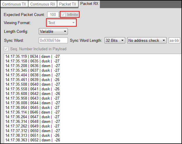
* Go to the `Packet RX` tab.
* In the tab, check of `infinite` packet count, set viewing format to `Text`, and click `Start`.
* Try moving the wire or jumper on the transmitter. Packets with the dawn state should show up in SmartRF Studio.
You should see something like the picture below. Note the red markings.