Introduction
==================================
This is the entry level guide on how to utilize the sensor controller with the GUI tool, Sensor Controller Studio (SCS). You will generate and debug code that will be loaded in the Sensor Controller (AUX) RAM and executed on on the sensor controller processor (16-bit custom low power RISC processor). This code can utilize the peripherals residing in the Sensor Controller Domain (AUX Domain). You will run and debug the full example code with the Sensor Controller Interface Driver (SCIF) on the CC2650 SensorTag + Debug DevPack in Code Composer Studio (CCS).
A good alternative to this guide is the getting started guide included with the SCS installer. A link to this document can be found on the start page in SCS. Within the mentioned guide there is a tutorial for the using the SmartRF06EB + CC2650EM called "Tutorial: Analog Light Sensor". The document can be found here after SCS is installed on your computer (for default install path):
`C:\Program Files (x86)\Texas Instruments\Sensor Controller Studio\docs`
Prerequisites
==================================
Software for Desktop development
---------
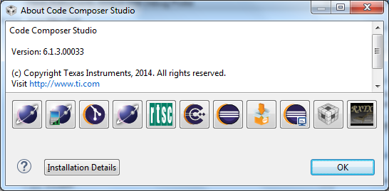
* CCS version 6.1 or later (tested with version `6.1.3.00033`)
* TI-RTOS (tested with version `2.20.01.08`)
* https://www.ti.com/tool/ti-rtos
* Sensor Controller Studio version 1.2.1 or later
* https://www.ti.com/tool/SENSOR-CONTROLLER-STUDIO
Hardware
---------
* 1x CC2650ST SensorTag
* 1x CC-DEVPACK-DEBUG (xds-110) or 1x SmartRF06EB (xds-100)
* Micro-USB Cable
Getting Started
==================================
Set up Desktop Environment
-------------------
1. Make sure CCS is installed ( version 6.1 or later). You can find version info in the menu 'Help->About Code Composer Studio'
2. Make sure TI-RTOS is installed. If it is installed to the default directory it should be located here:
`C:\ti\tirtos_cc13xx_cc26xx_2_20_01_08`
3. Run the `setup_sensor_controller_studio_xxx.exe` downloaded from the link above. When you start sensor controller studio the following examples will be populated here:
`%userprofile%/Documents/Texas Instruments/Sensor Controller Studio/examples`
Connect Hardware Alternative 2 (SmartRF06EB + SensorTag2.0)
-------------------
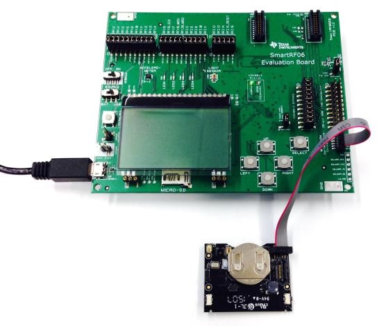
Disregard this option if you have selected alternative 1 (CC2650ST SensorTag + CC-DEVPACK-DEBUG (xds-110)). If you use the xds-100 debugger on the SmartRF06EB, connect the SmartRF06EB and SensorTag as shown in the image below. A 10-pin 1.27 mm pitch debug cable is used to connect the P410 header on the SmartRF06EB to the debug connector on the SensorTag.
Connect debugger and SensorTag
------------------------
When using the Debug Devpack (SimpleLink SensorTag Debugger DevPack), which contains the xds110 debugger, connect the SensorTag as shown in the figure below.
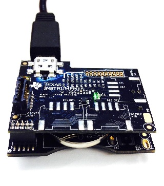
Start by making sure the SensorTag + Debug DevPack is connected to the PC via the USB cable.
{{y
Depending on the SensorTag board revision it may be necessary to first connect the DevPack to the PC and then connect the SensorTag to the Devpack. For version 1.2 you will have to insert the battery into the SensorTag before you connect USB to the debugger. After you plug in to a powered USB port, you can remove the battery again to power the whole device from USB instead of draining the coin cell battery. Make sure to verify that there is enough energy left in your battery to power up the device and run. For version 1.3 no battery needs to be inserted.
}}
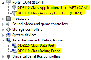
When the DevPack is connected, the Windows Device Manager (Start → Run → mmc devmgmt.msc → Ok) should show you the following devices connected:
Task 1 – Set Up Project in SCS
==================================
You will now configure and set up the `I2C-Light-Sensor` example code in SCS before you import the pre-made project into CCS. The driver source files must first be generated by the compiler before you open and compile the project in CCS.
Generate the Sensor Controller Driver
------------------------
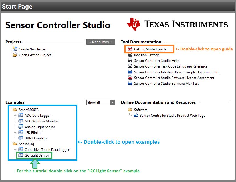
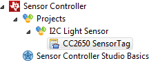
* Open SCS and double-click on the "I2C Light Sensor" example project as shown in the figure below.
On this start Page you can easily access the tool documentation for SCS. On the top right corner there is a link to the "Getting Started Guide" which contains a tutorial for testing the "Analog Light Sensor" example on the SmartRF06EB+CC2650EM. For this tutorial we will use the I2C Light Sensor example.
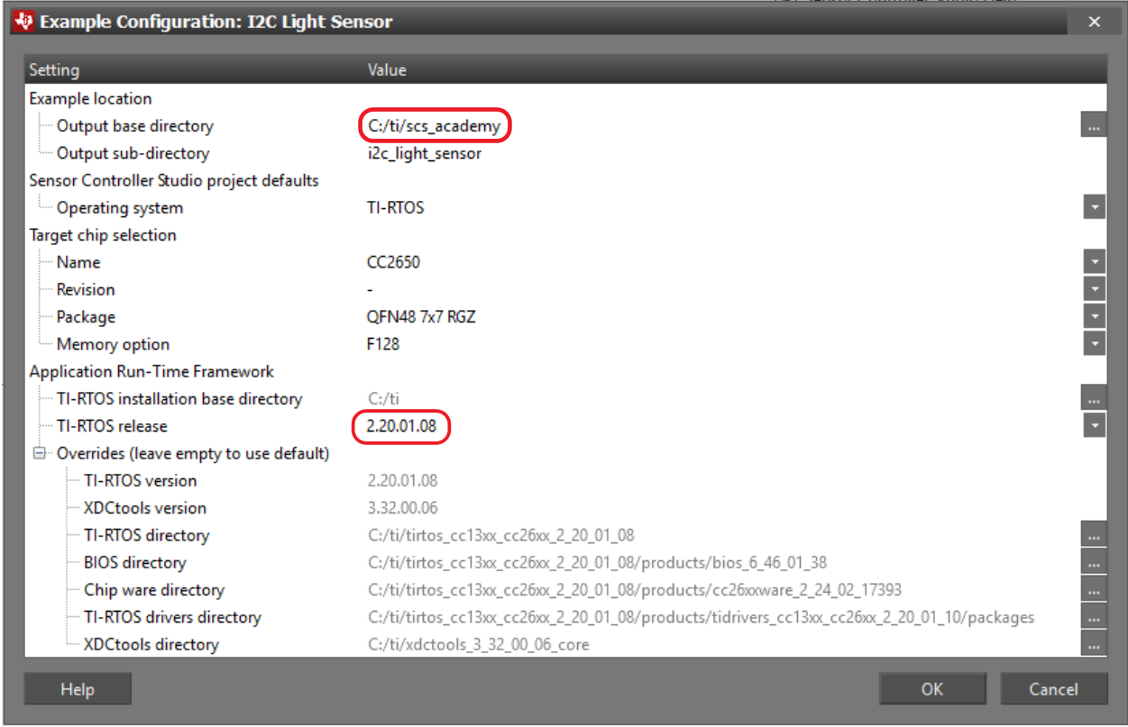
* After you double-click on the example project a new Example Configuration Window will appear. Make sure to select the same configuration as seen in the figure below. The TI-RTOS version 2.20.01.08 will be used in this tutorial.
* Change Output base directory to `C:\ti\scs_academy`.
When the project is opened in SCS, the project files will automatically be populated into the output base directory. The default path here is your documents folder `C:\Users\<your user>\Documents\Texas Instruments\Sensor Controller Studio\examples` where `<your user>` is your windows user name (`%USERPROFILE%`). After updating the example configurations, they should be as in the image below.
* Go to the Code Generator Pane in SCS (<kbd>CTRL+G</kbd>) and press "Generate driver source code".
* Verify that the driver is generated successfully in the event log. Then press View output directory (button is located at the bottom right corner).
[[d What does Sensor Controller Studio Generate?<br>(multiple correct answers)
[quiz_multi]
x> Example code to run on the main application processor
v> Driver Framework
v> Sensor Controller Processor Assembler Code
v> Operating System Abstraction Layer
[quiz_multi]
]]
SCS generates the SCIF driver and framework. The projects included with SCS are based on pre made example code which resides in the install directory `C:\Program Files (x86)\Texas Instruments\Sensor Controller Studio\examples`. This includes project files for IAR/CCS and main application source files (main.c/main_tirtos.c). Never open the examples from this location as they are used for restoring examples in your base output directory. To integrate a driver into your custom application you need to create your own main application source file (running on the main application processor). You can use the SCS examples as a reference and starting point. The Sensor controller firmware image is found in the driver file scif.c (pAuxRamImage). A more human-readable format of the sensor controller assembler source code is available in the listing file sce.lst.
Import to Code Composer Studio
------------------------
* Navigate to the `i2c_light_sensor_tirtos` project in the projects tab under Sensor Controller in SimpleLink Academy as seen in the image below.
* Press `Import the example project into CCS`
* Compile the project (<kbd>Ctrl + B</kbd>, or the hammer icon, or via Resource Explorer)
* Verify that the build completes without errors. If you have errors, go the the trouble shooting guide at the bottom of this page. If not, continue to the next section.
Configure the debugger connection
---------------------
The correct debugger type (XDS100v3 for SmartRF06, XDS110 for SensorTag and Launchpad) is selected by default when you import the project.
However, if you have more than one debugger of the same type connected, you have to manually select exactly which debugger should be used on a per-project basis. If you use the XDS100v3 debugger on the SmartRF06EB to connect with the SensorTag you can simply change the debugger from XDS110 to XDS100v3 in step 2a shown below.
[[+b Expand instructions for manual debugger selection in CCS Desktop
Make sure you only have one debugger of the same type connected when checking the serial number. This example is for XDS110, but the same applies to XDS100v3.
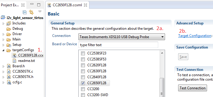
* Open the file `targetConfigs/CC2650F128.ccxml`.
* Change the connection to `XDS110 USB Debug Probe` if needed.
* Click on `Target Configuration`
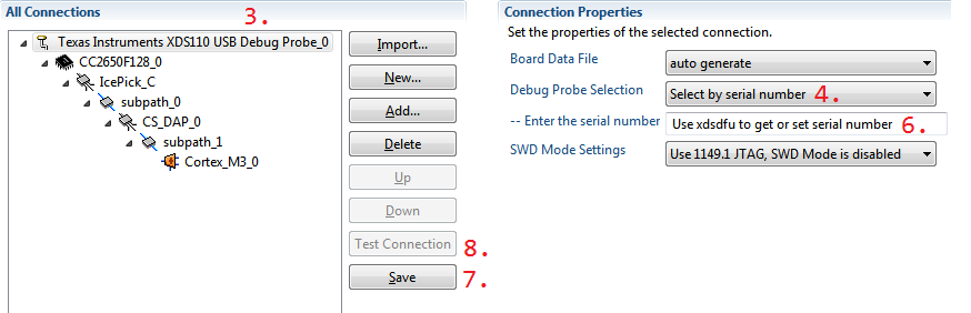
* Click on the top-level node (XDS110 USB Debug Probe)
* Choose 'Select by serial number'
* Start command prompt and call `c:\ti\ccs\ccs_base\common\uscif\xds110\xdsdfu.exe -e` to enumerate the connected debugger. This will give you the serial number of the device.
[[b XDS100v3 Serial number
For the XDS100v3 on the SmartRF06 board, find the serial number tool at `c:\ti\ccs\ccs_base\common\uscif\xds100serial.exe`. You cannot change the serial number with this tool.
]]
<div class="pre-container"><pre><div class="hljs"><span class="hljs-constant">C:\ti>c:\ti\ccs\ccs_base\common\uscif\xds110\xdsdfu.exe -e
USB Device Firmware Upgrade Utility
Copyright (c) 2008-2014 Texas Instruments Incorporated. All rights reserved.
Scanning USB buses for supported XDS110 devices...
<<<< Device 0 >>>>
VID: 0x0451 PID: 0xbef3
Device Name: XDS110 with CMSIS-DAP
Version: 2.2.4.2
Manufacturer: Texas Instruments
<span class="hljs-number">Serial Num: 0000FF01</span>
Mode: Runtime
Found 1 device.
C:\ti>
</span></div></pre>Finding XDS110 serial number</div>
* Insert the serial number. Above it's `0000FF01`.
* Save the settings.
* Test the connection.
* Do this for both the `App` and the `Stack` projects.
You can also change the serial number to something easier to remember, or in case two debuggers have the same serial number.
<div class="pre-container"><pre><div class="hljs"><span class="hljs-constant">C:\ti>c:\ti\ccs\ccs_base\common\uscif\xds110\xdsdfu.exe -m
USB Device Firmware Upgrade Utility
Copyright (c) 2008-2015 Texas Instruments Incorporated. All rights reserved.
Scanning USB buses for supported XDS110 devices...
<<<< Device 0 >>>>
VID: 0x0451 PID: 0xbef3
Device Name: XDS110 with CMSIS-DAP
Version: 2.2.4.2
Manufacturer: Texas Instruments
Serial Num: BADEABBA
Mode: Runtime
Switching device into DFU mode.
C:\ti>c:\ti\ccs\ccs_base\common\uscif\xds110\xds110\xdsdfu.exe -s ABCDEF01 -r
USB Device Firmware Upgrade Utility
Copyright (c) 2008-2015 Texas Instruments Incorporated. All rights reserved.
Scanning USB buses for supported XDS110 devices...
Setting serial number to "ABCDEF01"...
c:\ti>
</span></div></pre>Optionally change the serial number</div>
+]]
Task 2 - Download and Debug with CCS
==================================
* Make sure that your HW is connected as instructed earlier in this guide.
* Press the Debug button (bug icon) or press press <kbd>F11</kbd> to start the debug session.
* Then press Resume (<kbd>F8</kbd>) to allow the code to run. The light sensor is read at the given interval and if the value increase more than the configurable amount, the red led blinks. If the value decrease more than the configurable amount, the green led will blink.
Breakpoints and source browsing in CCS
---------------------
* Insert breakpoints on the two Task_sleep calls in main_tirtos.c (see below) in CCS by double clicking the desired lines or pressing <kbd>CTRL+SHIFT+B</kbd>.
```c
// The light sensor value is outside of the configured window ...
uint16_t value = scifTaskData.i2cLightSensor.output.value;
if (value < lowThreshold) {
// Below the low threshold, so blink LED1
PIN_setOutputValue(hLedPins, Board_LED1, Board_LED_ON);
Task_sleep(10000 / Clock_tickPeriod); // Set breakpoint here
PIN_setOutputValue(hLedPins, Board_LED1, Board_LED_OFF);
} else if (value > highThreshold) {
// Above the high threshold, so blink LED2
PIN_setOutputValue(hLedPins, Board_LED2, Board_LED_ON);
Task_sleep(10000 / Clock_tickPeriod); // Set breakpoint here
PIN_setOutputValue(hLedPins, Board_LED2, Board_LED_OFF);
}
```
* Now run the application (<kbd>F8</kbd>) and vary the input light level to the sensor and observe the behaviour.
* Find the address of the scifTaskData struct. Tips: press <kbd>CTRL+H</kbd> for advanced search options in CCS.
[[d Quiz
Where is the variable scifTaskData.i2cLightSensor.output.value located?
[quiz]
x> System FLASH
x> Main Application RAM
v> Sensor Controller (AUX) RAM
[quiz]
Can the Sensor Controller access the Main application RAM?
[quiz]
v> No
x> Yes
[quiz]
]]
* Find out in which context the scTaskAlertCallback function is called.
[[d Quiz
Which event will trigger the Hardware Interrupt (HWI) hwiTaskAlert that will post the semaphore (semScTaskAlert) that allows the application task to continue from pending?
[quiz]
x> INT_AON_PRG0
v> INT_AON_AUX_SWEV1
x> INT_AON_AUX_SWEV0
[quiz]
]]
* Terminate the i2c_light_sensor project (<kbd>Ctrl + F2</kbd> or red square icon).
Task 3 - Download and Debug with SCS
==================================
In this task you will debug the sensor controller task directly from Sensor Controller Studio. Sensor Controller Studio taking over the role of the System CPU application and interacting with the Sensor Controller task through the debugger. More detailed information about this can be read in the SCS Help viewer (press <kbd>F1</kbd> in SCS and go to `Task Testing Panel`). We will now debug the sensor controller task without any application running on the main application processor.
[[d Quiz
Is it currently possible to debug both code on the main application processor and the sensor controller at the same time (concurrently)?
[quiz]
v> No
x> Yes
[quiz]
]]
* In SCS, go to the Task Testing panel by either clicking on the tab or pressing <kbd>Ctrl + T</kbd>.
* In the Task Testing window, if you have multiple projects open, make sure to select the I2C Light Sensor project like shown in the screenshot below.
When taking over the role of the System CPU application during task testing and debugging, SCS cannot interact with the Sensor Controller in real-time, and also has no knowledge of what a task iteration (during task testing) actually is. The sequence of events that will occur during a task iteration must therefore be specified, and this is done by listing a sequence of actions. In this example you can simply set up `Run Execution Code` and `Run Event Handler Code` sequentially.
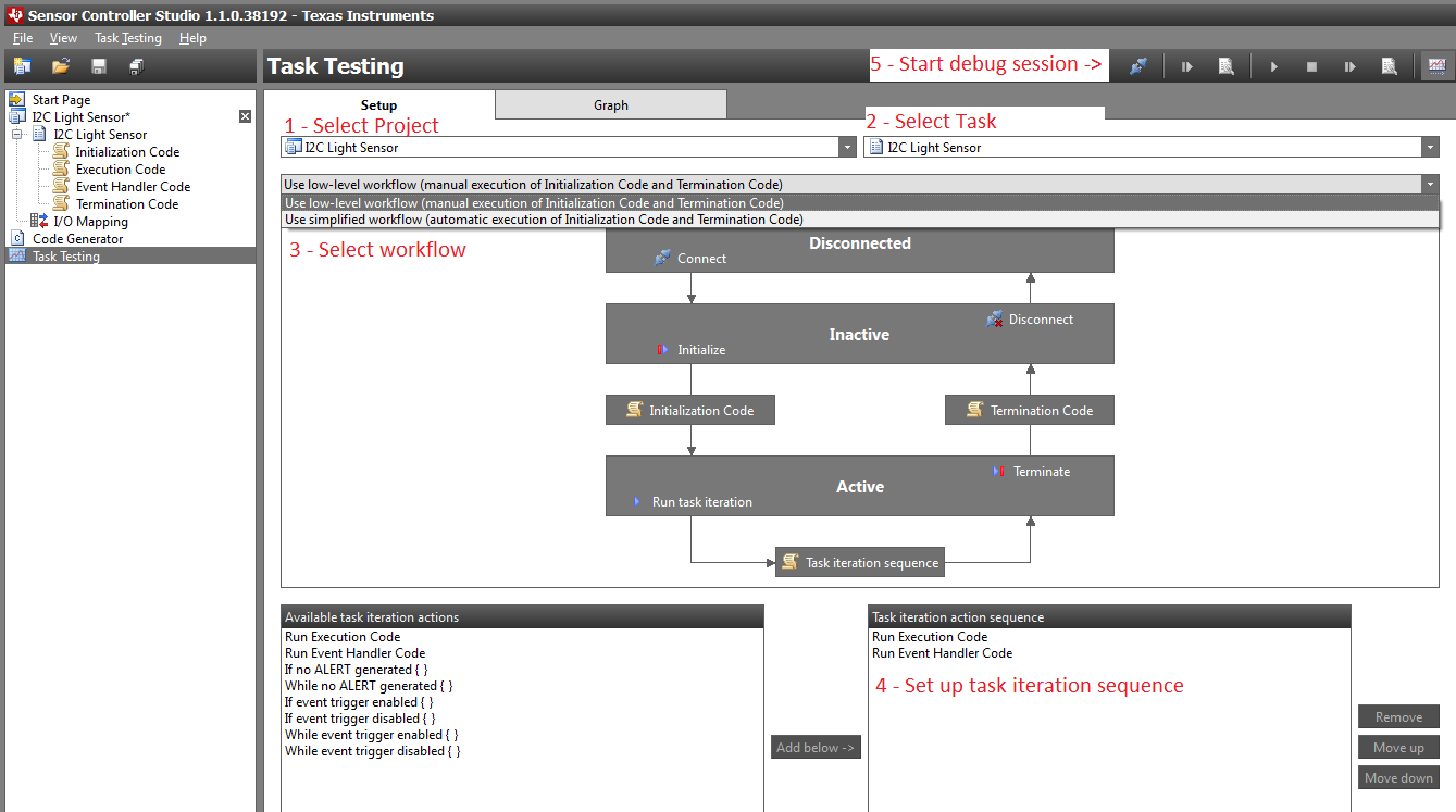
* Start a debug session by connecting to target (<kbd>F12</kbd>).
* Run the initialization code once (<kbd>F6</kbd>).
* Run task iterations continuously (<kbd>F5</kbd>).
* Put your hand over the light sensor and observe the light sensor value in the graph window like is done in the screen shot below.
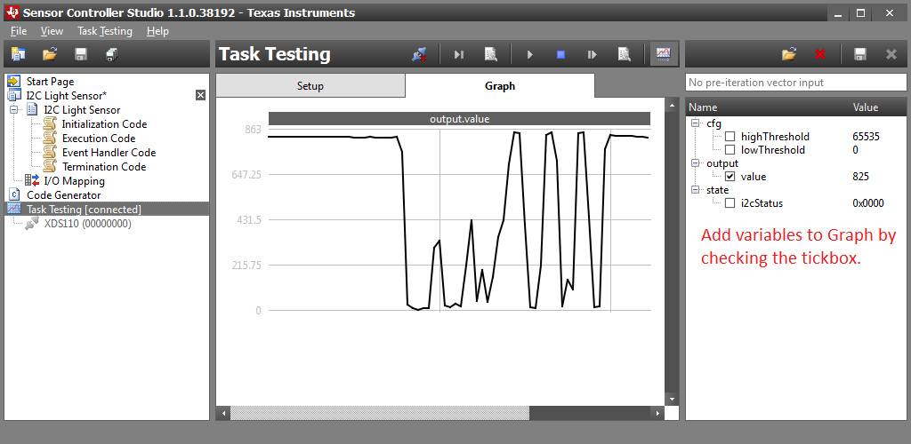
The icons and hot keys for debugging alter meaning and form during each step which means the hot keys, for example <kbd>F6</kbd>, have different actions during the different phases. This makes it easier to restart the execution code as you can press <kbd>F6</kbd> - <kbd>F6</kbd> or press the same icon twice to run termination code and initialization code again before starting the execution code again. Now you will start a debugging session.
* When you are satisfied press stop (<kbd>F6</kbd>).
* Run the termination code (<kbd>F6</kbd>).
* Run the initialization code once (<kbd>F6</kbd>).
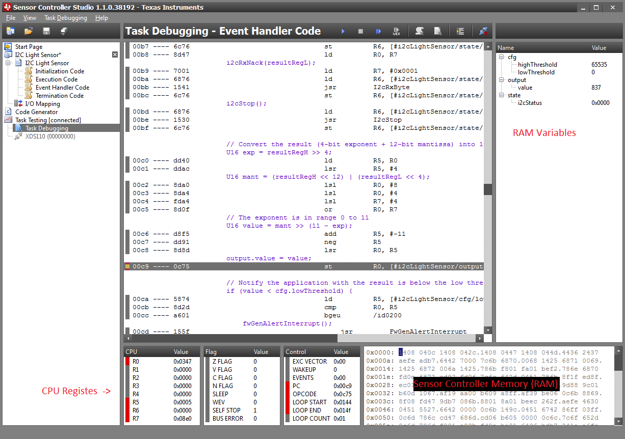
* Start a debug session of one task iteration (<kbd>CTRL + F11</kbd>).
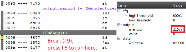
* Place a breakpoint as shown in the image below where the light sensor value is stored to the RAM variable output.value (<kbd>F9</kbd>).
* Press run continuously (<kbd>F5</kbd>).
* Then end the current task code block (execution code) and continue with the next (event handler code) (<kbd>F8</kbd>).
* Press run continuously (<kbd>F5</kbd>).
* Now you should hit the breakpoint. Single step in the code by pressing <kbd>F11</kbd> and observe the new value being loaded into output.value (seen on right pane). Now flip the SensorTag up-side down and repeat the process
(<kbd>F5</kbd> - <kbd>F8</kbd> - <kbd> CTRL + F11</kbd> - <kbd>F5</kbd> - <kbd>F8</kbd> - <kbd>F5</kbd>) and verify that the new value is very low due to very few light waves and/or particles hitting the sensor. Unfortunately it is not possible to simply restart the execution code without going through the steps mentioned above, but the breakpoint set will remain and does not have to be enabled again.
Task 4 - Understand and Modify
==================================
The i2c_light_sensor task reads the OPT3001 light sensor at an interval. The light sensor is configured for 100 ms integration, and a single measurement is started by issuing a command to the sensor over I2C in the task execution code. To allow the sensor controller to enter sleep and save power while the sensor is integrating, a timer event trigger is set up to allow the sensor controller to enter sleep. 120 ms after the measurement command is sent to the sensor the sensor controller wakes up to read the results from the sensor over I2C and and process it accordingly.
Review Task Code and Event Code
---------------------
Browse the different task codes (initialization, execution, event handler, termination) and answer the following quiz.
[[d Quiz
How many times will the Initialization code run in the i2c_light_sensor example? ( Hint: scifCtrlTasksNbl in scif_framwork.c )
[quiz_multi]
v> Once
x> Every time the device comes out of STANDBY
x>
[quiz_multi]
How often will the Execution code run in the i2c_light_sensor example? ( Hint: fwScheduleTask procedure in SCS)
[quiz]
x> every millisecond
x> every 100 milliseconds
v> every second
x> every 10 seconds
[quiz]
How often will the Event Handler code run in the i2c_light_sensor example? ( Hint: evhSetupTimerTrigger procedure in SCS )
[quiz]
x> every 100 milliseconds
v> 100 milliseconds after every execution code iteration
x> never
x> when a GPIO input level changes
[quiz]
How often will the Termination code run in the i2c_light_sensor example? ( Hint: fwScheduleTask )
[quiz]
v> Never
x> Before the Device goes in to standby
[quiz]
]]
Get the Manufacturer ID from the light sensor
---------------------
Modify the the initialization code to retrieve the Manufacturer ID from the OPT3001 light sensor. Look at the implementation done in the execution and event handler code and change the values according to the table given below.
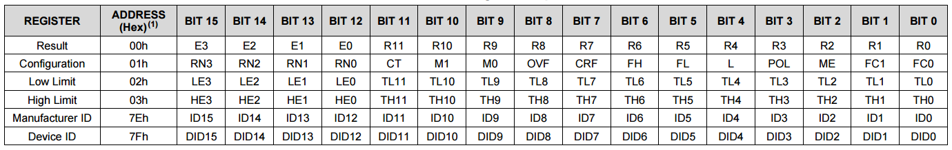
Ambient Light Sensor (OPT3001) data sheet : https://www.ti.com/lit/ds/symlink/opt3001.pdf
[[d Quiz
Which value is reported from the opt3001 sensor as a valid manufacturer ID? (Multiple correct answers)
[quiz_multi]
v> 21577 (decimal)
x> FFFF (hexadecimal)
v> 5449 (hexadecimal)
v> The letters "TI" in ASCII
[quiz_multi]
]]
Retrieve the value by storing it in a output.variable. Use the low-level workflow in the SCS task testing menu and enter the initialization code in the task debugging panel. Place a breakpoint in the assembler code (place immediately after the instruction that stores values in your output variable) and read the updated value. Now you are ready to answer the quiz below. You might need to run through the termination code before you restart to allow the sensor to reset. Try on your own before looking at the solution below.
Initialization Code Solution:
---------------------
[[+b Expand Solution
```c
U16 ManufacturerIdHigh;
U16 ManufacturerIdLow;
U16 DeviceID;
// Read the Manufacturer ID
i2cStart();
i2cTx(I2C_OP_WRITE | ALS_I2C_ADDR);
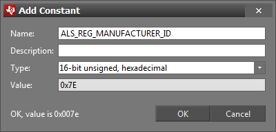
i2cTx(ALS_REG_MANUFACTURER_ID);
i2cRepeatedStart();
i2cTx(I2C_OP_READ | ALS_I2C_ADDR);
i2cRxAck(ManufacturerIdHigh);
i2cRxNack(ManufacturerIdLow);
output.manuId = ManufacturerIdLow;
output.manuId |= (ManufacturerIdHigh << 8);
i2cStop();
// Schedule the first execution
fwScheduleTask(1);
```
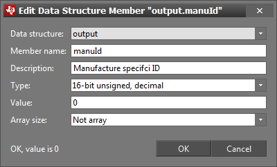
+]]
Trouble Shooting Guide
==================================
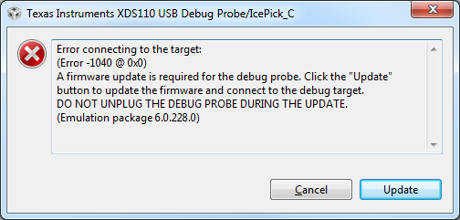
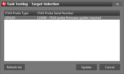
Emulator firmware update
---------------------
You might get a query to upgrade the XDS110 emulator firmware when conneccting with SCS after CCS and vice versa. Simply press update each time and wait for the firmware update to complete.