Introduction
==================================
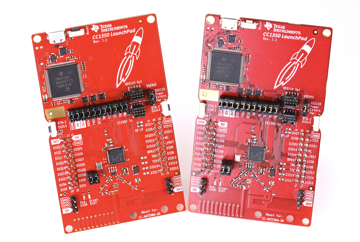
The CC1350 LaunchPad is TI's first Dual Mode kit utilizing the CC1350 which enables Sub-1GHz + BLE in a single chip solution. This new LaunchPad kit brings easy and low cost sub-1GHz proprietary RF connections to the LaunchPad ecosystem with the SimpleLink ultra-low power CC13xx family of devices. This LaunchPad kit brings support for the CC1350 wireless MCU
The CC1350 device is a wireless MCU featuring sub-1GHz RF GFSK, Long Range Mode (LRM, a direct sequence spread spectrum modulation format), and other sub-1GHz modulations - in addition it supports 2.4GHz RF! The CC1350 device contains a 32-bit ARM™ Cortex™-M3 processor that runs at 48 MHz as the main processor and a rich peripheral feature set that includes a unique ultra-low power sensor controller. This sensor controller is ideal for interfacing external sensors and for collecting analog and digital data autonomously while the rest of the system is in sleep mode.
The CC1350 LaunchPad is supported by a large set of software examples in the TI-RTOS CC13xx/CC26xx SDK, showing best practice on how to implement and use different features of the CC1350. An overview for the software examples can be found on this web page. The CC1350 is also supported by the TI BLE software stack, which enables full BLE connectivity.
Hardware Prerequisites
--------------------------
For this Out of the box project you'll need at least two CC1350 Launchpads to transmit and receive data between them, one LaunchPad will act as a concentrator and one or more will act as nodes in a wireless sensor network. Both the Concentrator and Node Launchpads can be connected to a LCD Boosterpack.
* Two CC1350 LaunchPads
* Two Micro USB Cables
* Optional: Two 430BOOST-SHARP96 LCD Boosterpacks
Out of the Box Demo
==================================
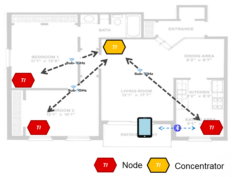
The CC1350 LaunchPad is pre-programmed with the TI BLE stack, allowing you to connect to the device using e.g. the SensorTag iOS/Android smartphone app. When connected the cc1350 device offers the same functionality as e.g. the cc2650 Lanuchpad. Using the built in BLE Over the Air Download (OAD) one can easily convert the CC1350 device from a BLE device into e.g. a sub-1GHz device, due to the dual mode capabilites of the CC1350. In this step by step guide we will show you how to download new application images to create a small wireless sensor network. The sensor network includes a concentrator that receives sub-1GHz data and Nodes that send data over the sub-1GHz link to the concentrator and in addition reconfigures the radio core on the fly to send out BLE advertisement packets. A high level overview of the complete demo is shown in the picture below
[[r Note!
To restore the pre-programmed firmware image, go to the **Restoring BLE stack/app mode** section further down in this document.
]]
* Nodes spends most of the time in standby to ensure lowest possible power consumption. It samples the ADC sensor once every second using the Sensor Controller. The node then send its sensor data to the concentrator over sub-1GHz (50kbps, GFSK) link.
* The sensor data is: ADC value, battery level, time since last reboot, number of packets sent and the button state (BTN-1).
* The Node then reconfigures the radio into BLE mode and send out BLE beacons, aften this the node enter standby until it is time to read the ADC again.
* Concentrator is in always RX ready to receive data over the sub-1GHz link and displays the data on LCD/UART.
Both the Node and Concentrator can be configured to send out BLE advertisement packets by pressing BTN-2.
The supported BLE advertisement formats supported are:
1. Manufacturer Specific (MS) + Eddystone URL, this mode can be used with the TI SensorTag app and any app that supports Eddystone. This is the default mode for Node.
2. Manufacturer Specific (MS).
3. Google Eddystone URL + TLM (interleaved), Google's Open Source BLE beacon format which can be used with any Eddystone compatible app.
4. Google Eddystone UID + TLM (interleaved)
5. None. This is the default for Concentrator.
Pre-Work
--------------------------
Most of the functionality is supported in both the iOS and the Android version of the SensorTag app, but please note that OAD functionaly is currently only supported on iOS.
1. Download and install TI SensorTag App from App Store (iOS) or Android Market.
This app is used to:
* Interact with CC1350 when in BLE connected mode
* Observe MS (Manufacturer Specific) beacons
* OAD update of the sub-1GHz images to the CC1350LaunchPad
2. Download and install Google Chrome from App Store (iOS) or Android Market.
This app is used to:
* Observe Google Eddystone beacons (URL, TLM and UID frame formats)
Go to [this link](https://support.google.com/chrome/answer/6239299?hl=en) to setup notifications for Chrome on your iOS or Android device.
Running the BLE stack/app
--------------------------
1. Power up one CC1350 LaunchPad by connecting it to your PC with the USB cable.
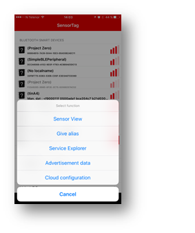
2. On your smartphone, start the SensorTag app.
3. Connect to the CC1350 LaunchPad by clicking it and select **Sensor view**.<br>
Tip: If using several BLE devices, you can identify your device by pressing BTN-1.
4. You can now use the SensorTag app to control the device via the BLE connection and e.g.
- Read sensors and view data
- Toggle GPIOs
- Push data to the cloud
- FW download using the OAD service
Download firmware images
--------------------------
In this step we will use a BLE connection to download a new firmware image to the device.
Two different firmware images are provided out of the box:
- sub-1GHz Coordinator
- sub-1GHz Node
The binary images are included in the SensorTag app in versions for use in both EU and US.
1. In the SensorTag app, connect to the device as described above, then select **FW Download**.
2. Create one CC1350 LaunchPad to act as sub-1GHz Coordinator:
1. Click "select FW file"
2. Scroll down and select rfWsnDmConcentratorOad_CC1350_LAUNCHXL_x.bin (x=EU or US version)
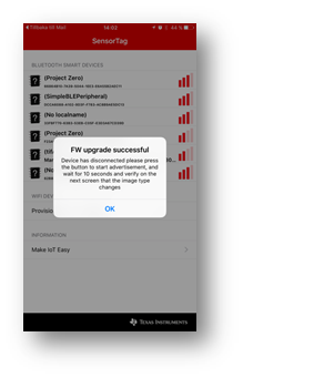
3. Wait until you see FW Upgrade successful message box.
4. The device will reset and start running the new firmware image. If device does not reset automatically, press the reset button.
3. Create one (or more) CC1350 LaunchPad(s) to act as a dual mode sub-1GHz/BLE beacon Node:
1. Click "select FW file".
2. Scroll down and select rfWsnDmNodeOad_CC1350_LAUNCHXL_x.bin (x=EU or US version).
3. Wait until you see FW Upgrade successful message box.
4. The device will reset and start running the new firmware image. If device does not reset automatically, press the reset button.
Running the sub-1GHz firmware images
------------------------------------
Now when the devices has been updated with new firmware, let's have a look at their new functionality!
1. Power on the Concentrator
- If no display boosterpack is used, connect UART (Application/User UART) with your favorite terminal application, use settings 115200 8N1.
- It will display 'Waiting for nodes' on UART and LCD (LCD optional), once a node sends data to the concentrator it will be displayed.
2. Power on the Node(s).
- Node will send sensor data over sub-1GHz link to the Concentrator at least every 5 seconds, or if the ADC reading changes by a certain amount.
- The ADC is sampled with 1Hz.
- After data has been sent on the sub-1GHz interface BLE beacons are also sent.
- Red LED blink indicates sub-1GHz TX wihle green LED blink indicates BLE beacon TX.
3. Observe BLE beacons and sub-1GHz wireless sensor network in action!
- The BLE beacons that the devices send out can now be observed using the TI SensorTag app, for MS beacons, and e.g. Google Chrome for Eddystone beacons.
- The SensorTag app show the state of BTN-1 in beacon, while the Eddystone compliant app can show the URL/UID and TLM data.
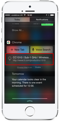
- By default the Node send out a Eddystone URL frame with a link to https://www.ti.com/product/cc1350, if you configure Google Chrome as per above you will see it in the notification center:
**Node details**
- Press BTN-1 on Node, the button state is sent out both in the data payload for the sub-1GHz interface and in a BLE beacon.
- BTN-1 also starts fast (1s interval) report interval for 30s.
- Node send BLE beacons that can be picked up by any BLE capable device.
- By default the Node is sending BLE beacons with Eddystone URL + MS (prop) frame format. Press BTN-2 to toggle between supported BLE beacon formats, as described above.
**Concentrator details**
- The Concentrator can also be configured to send BLE beacons, similar to Nodes. Use BTN-2 to cycle through beacon types.
- The BLE beacon payload is forwarded from a selected node forming a bridge between the sub-1GHz and BLE interfaces.
- The ***** next to the Node on Concentrator's LCD/UART indicate which node's data is being used to send the BLE beacon.
- BTN-1 on the Concentrator is used to cycle through Nodes when multiple nodes are connected.
Restoring BLE stack/app mode
==================================
It is possible to get back to BLE stack/app mode, running the full BLE stack, by pressing both buttons down for 10s.
The device will then restart in BLE mode, indicated by green LED blinking when sending BLE beacons.
If the Launchpad has been flashed with code without BLE Stack/app mode bootloader, e.g. other TI-RTOS examples, you have to manually flash the Launchpad.
1. [Right-click on this link](resources/CC1350LaunchPad_BLE_All_v1_00.hex), and choose **Save link as..**
2. Use the Flash Programmer 2 application to flash the hex file to the Launchpad. If you don't have it installed, it can be downloaded [here](https://www.ti.com/tool/flash-programmer).
3. Verify the download by pressing the reset button. Both LEDs should be flashing for a few seconds.
[[r! Erase External SPI Flash
The external SPI flash is used to store firmware images, under some circumstances it might be necessary to erase it before loading the BLE stack/app.
If you are having issues with restoring the BEL stack/app, e.g. that it does not start as expected, [right-click on this link](resources/launchpad_wipeflash.hex), and choose **Save link as..**, then flash this hex file to your launchpad and let it run until the LEDs stop blinking.
Then proceed with flashing the BLE stack/app file as described above.
]]
A Closer Look at the Hardware
==================================
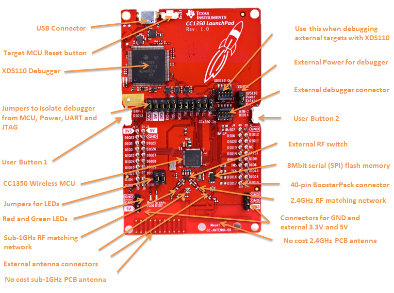
- On-board emulation tool for flashing & debugging firmware on the target CC1350 device.
- 40-pin dual-gender BoosterPack connectors
- CC1350 Wireless Micro controller device
- User red & green LED
- 2x User switches
- Access to all pins of the CC1350 device
- Connector for external Antennas, both sub-1GHz and 2.4GHz
- External RF switch to select between sub-1GHz or 2.4GHz path
- 8Mbit external serial (SPI) Flash memory
Power supply requirements
--------------------------
The LaunchPad is designed to be powered from a USB-compliant power source, either a USB charger or a computer. When used this way, jumpers need to be mounted on the 3V3 position of the central jumper block. An LDO powered from the USB VBUS supply supplies 3.3V to the XDS debugger, the CC1350, and associated circuitry including the 3V3-marked pins for BoosterPacks.
Temperature range
-----------------
The LaunchPad is designed for operation -25 to +70 C. Note that other BoosterPacks and LaunchPads may have different temperature ranges, and when combined, the combination will be set by the most restrictive combined range.
Advanced use of the LaunchPad hardware
--------------------------------------
**Jumper block**
The jumper block in the middle of the board can be used to disconnect the upper section (XDS110 debugger) from the bottom section (CC1350). The jumpers are mounted by default. If you want to debug the CC1350 from an external debugger, you need to remove all the jumpers and connect the debugger to the socket marked CC1350 In.
It is also possible to use the CC1350 LaunchPad to debug external targets. In this case, remove all the jumpers and connect the external target to the socket marked XDS110 Out.
The jumper block marked VSENSE can be used to select the source of power to the CC1350. Usually, power is supplied from USB and a jumper is mounted in the position marked XDS110 power (factory default). If you want to power CC1350 from an external supply, move the jumper to the position marked Extern. Pwr, and connect the external supply to the 3V3 pin on J1. Also make sure to remove the 3V3 jumper from the main jumper block. Make sure that the voltage applied stays within the supply range of the CC1350.